Open -Package Inspection
Please check if there is any obvious damage to the device appearance and confirm if the
accessories are in accordance with those on the packing list when opening the outer
packing container. Please refer to packing list for details with exact model for actual
configuration
Device Structure
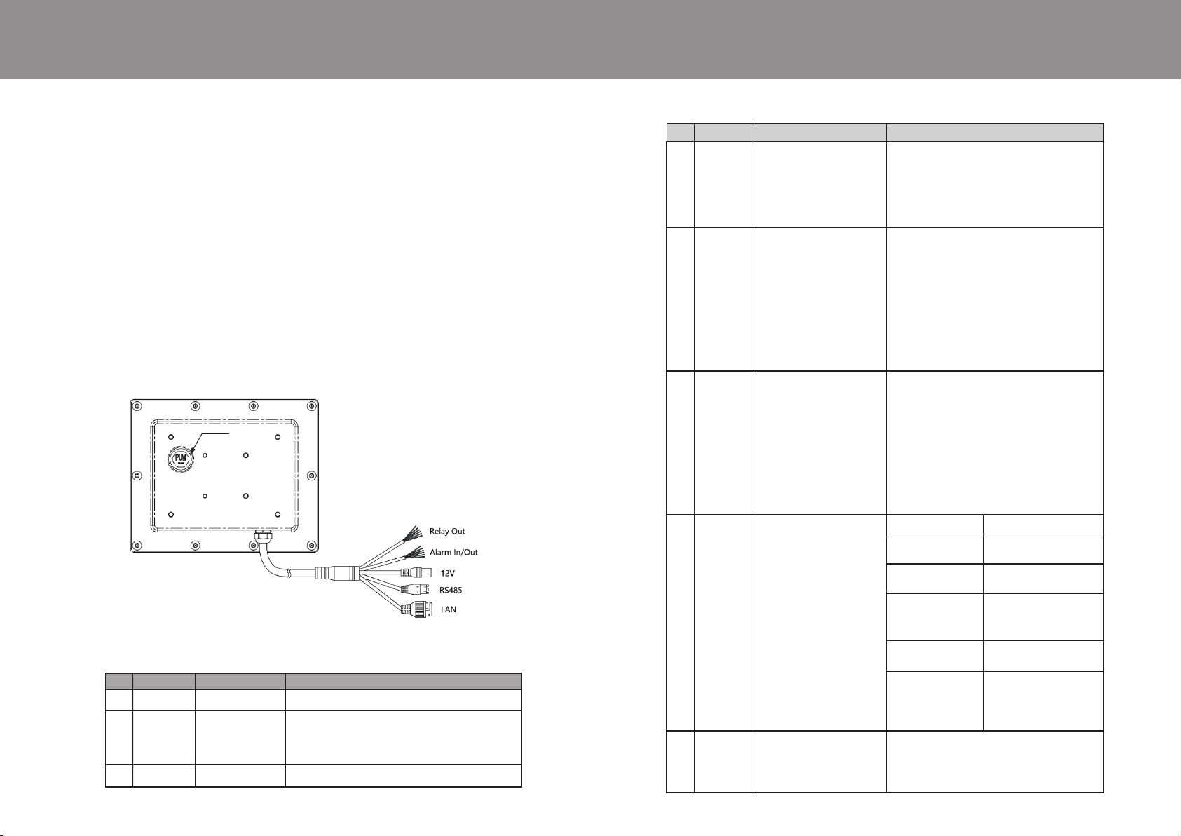
2.1 Port Definition
Note:
● The following structure fig. is for reference only. It shows the functions of device
external ports
● There might be minor differences between different devices, please refer to the
actual product you purchased.
Fig. 2-1
Table 2-1
Table 2-1 External port definition and description
1.
2.
频谱探测装置
Millimeter Wave Radar Millimeter Wave Radar
2
● ●
1
● ●
No.
1 LAN
2 Power
3
Signal line
Network Port
Power input port
RS485
Cable Port Port Name Function Description
Connect to standard Ethernet and power the PoE
Input DC 12V
Note : Equipment may be damaged if power is
not supplied in accordance with the instructions.
Transmit radar data(object information) via RS485
No. Cable Port Port Name Function Description
4
5
6
7
8
Signal line
Signal line
Signal line
LED
indicator
light
Reset
Optocouple output:
Switch output(dry cont-
act):Normally on, able to
withstand current<50mA
Relay output:
Switch output(dry contact):
Able to withstand current
(Resistive load):2A@30V、
0.5A@125V AC(Full load el-
ectrical durability:100000
times) If the tolerance, sen-
sibilityLoad, please keep the
current allowance in place.
High and low level input:
It's the optocoupler drive
end, which requires driving
Current 0.3~20 mA.
Related parameters desc-
ription: light-emitting dio-
des (leds) pressure drop 1.2 V,
radar board built-in 200 Ω
current-limiting resistor.
Red-green LED statue
Indicator light, show the
working state of the equi-
pment
Reset key
Green breath flashing
Green flashing
Red and green always
ON
Red breath flashing
Radar flashing
Red and green always
OFF
The device reset button enables the device to resto-
re factory Settings. Open the valve on the device
and press the reset button frequently with the stylus
until the device restarts.
Radar works normal
Radar works normal and
connected with PC software
Radar access system protec-
tion
Radar works abnormal,
please check if radar out-
put objects normally.
Radar is detecting the movi-
ng target
①Radar input power abno-
rmal, radar not power on.
②If the power is normal,
radar was broken.
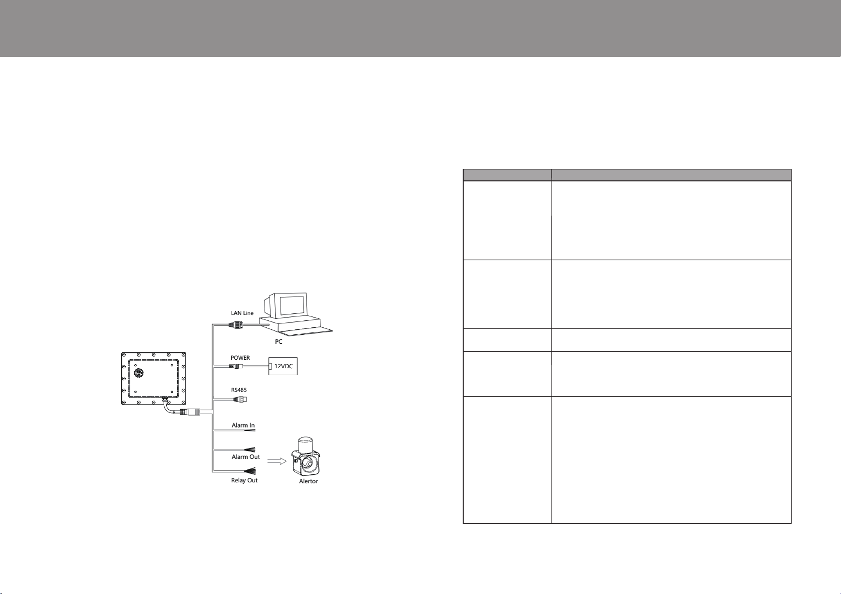
2 sets of switch quantities, line definition as
below:Grey-black=Alarm out1_M;
Orange-black=Alarm out1_N;
Yellow-white=Alarm out2_M;
Yellow-black=Alarm out2_N.
2 sets of switch quantities, line definition as
below:Pink=NC1; Light green=COM1;
Brown=NO1;Purple=NC2;
Brown-black=COM2; Gray=NO2
NC: Normal close; COM: Public port;
NO: Normal open
The radar can receive an external input
trigger signal, so that the radar performs
a corresponding response action;
Line sequence definition:
white = signal input + ;
white/black = signal input - ;
Reset