manuals.online logo
Brands
  1. Home
  2. •
  3. Brands
  4. •
  5. Unigas
  6. •
  7. Burner
  8. •
  9. Unigas P60 VS Operating manual

Unigas P60 VS Operating manual

M039576CA 0.1 04/2023
BURNERS - BRUCIATORI - BRULERS - BRENNER - QUEMADORES -
ГОРЕЛКИ
electronically controlled
short-flame gas burners
MANUAL OF INSTALLATION - USE - MAINTENANCE
P60 VS
P72 VS
P73 VS
LMV5x
2
DANGERS, WARNINGS AND NOTES OF CAUTION
The following:
Entails the customer’s acknowledgement and acceptance of the com-
pany’s general terms and conditions of sale, in force at the date of
order confirmation and available in the appendix to the current price
lists.
Is intended exclusively for specialised, experienced and trained users
able to operate in conditions that are safe for people, the device and
the environment, and in full compliance with the requirements set out
on the following pages and with current health and safety regulations.
Information regarding assembly/installation, maintenance, replacement
and repair is always and exclusively intended for (and therefore only to be
carried out by) specialised personnel and/or directly by the Authorised
Technical Service
IMPORTANT :
The supply has been made at the best conditions on the basis of the
customer’s order and technical indications concerning the state of the pla-
ces and the installation systems, as well as the need to prepare certain
certifications and / or additional adaptations with respect to the standard
observed and transmitted for each product. In this respect, the manufac-
turer declines any responsibility for complaints, malfunctions, criticalities,
damages and/or anything else consequent to incomplete, inaccurate and/
or missing information, as well as failure to comply with the technical
requirements and installation regulations, initial start-up, operational
management and maintenance.
For proper operation of the device, it is necessary to ensure the readabi-
lity and conservation of the manual, also for future reference. In case of
deterioration or more simply for reasons of technical and operational
insight, contact the manufacturer directly. Text, descriptions, images,
examples and anything else contained in this document are the exclusive
property of the manufacturer. Any reproduction is prohibited.
RISK ANALYSIS
Instruction manual supplied with the burner:
This is an integral and essential part of the product and must not be sepa-
rated from it. It must therefore be kept carefully for any necessary consul-
tation and must accompany the burner even if it is transferred to another
owner or user, or to another system. In the event of damage or loss, ano-
ther copy must be requested from the local customer service centre;
Delivery of the system and instruction manual
.
The supplier of the system is obliged to accurately inform the user about:–
Use of the system;
– any further testing that may be necessary before activating the system;
– maintenance and the requirement to have the system checked at least
once a year by a contractor or other specialised technician.
To ensure periodic monitoring, the manufacturer recommends drawing up
a Maintenance Agreement.
WARRANTY AND LIABILITY
In particular, warranty and liability claims will no longer be valid in the
event of damage to persons and/or property if such damage is due to any
of the following causes:
- Incorrect installation, start-up, use and maintenance of the burner;
- Improper, incorrect or unreasonable use of the burner;
- Operation by unqualified personnel;
- Carrying out of unauthorised changes to the device;
- Use of the burner with safety devices that are faulty, incorrectly applied
and/or not working;
- Installation of untested supplementary components on the burner;
- Powering of the burner with unsuitable fuels;
- Faults in the fuel supply system;
- Use of the burner even after an error and/or fault has occurred;
- Repairs and/or overhauls incorrectly carried out;
- Modification of the combustion chamber with inserts that prevent the
regular development of the structurally established flame;
- Insufficient and inappropriate supervision and care of the burner compo-
nents most subject to wear and tear;
- Use of non-original components, whether spare parts, kits, accessories
and optionals;
- Force majeure.
Furthermore, the manufacturer declines all responsibility for non-
compliance with this manual.
Personnel training
The user is the person, organisation or company that has acquired the
appliance and intends to use it for the specific purpose. The user is
responsible for the appliance and for training the personnel that operate it.
The user:
- Undertakes to entrust the machine to suitably trained and qualified per-
sonnel;
- Must take all measures necessary to prevent unauthorised people gai-
ning access to the appliance;
- Undertakes to adequately inform personnel about application and obser-
vance of the safety requirements, and therefore ensure that they are
familiar with the operating instructions and safety requirements;
- Must inform the manufacturer if any faults or malfunctions of the acci-
dent prevention systems occur, and if there is any suspected danger;
- Personnel must always use the personal protective equipment required
by law and follow the instructions provided in this manual;
- Personnel must observe all danger and caution notices on the
appliance;
- Personnel must not carry out, on their own initiative, operations or inter-
ventions outside their area of expertise;
- Personnel must inform their superiors of any problem and danger that
may arise;
- The assembly of parts of other makes, or any modifications made, may
alter the characteristics of the appliance and may therefore compromise
operational safety. The manufacturer therefore declines all responsibility
for damages arising from the use of non-original parts.
GENERAL INTRODUCTION
The equipment must be installed in compliance with the regulations in
force, following the manufacturer’s instructions, by qualified personnel.
Qualified personnel means those having technical knowledge in the
field of components for civil or industrial heating systems, sanitary hot
water generation and particularly service centres authorised by the
manufacturer.
Improper installation may cause injury to people and animals, or
damage to property, for which the manufacturer cannot be held liable.
Remove all packaging material and inspect the equipment for integrity.
In case of any doubt, do not use the unit - contact the supplier.
The packaging materials (wooden crate, nails, fastening devices, plastic
bags, foamed polystyrene, etc), should not be left within the reach of chil-
dren, as they may prove harmful.
Before any cleaning or servicing operation, disconnect the unit from
the mains by turning the master switch OFF, and/or through the cutout
devices that are provided.
Make sure that inlet or exhaust grilles are unobstructed.
In case of breakdown and/or defective unit operation, disconnect the
unit. Make no attempt to repair the unit or take any direct action.
Contact qualified personnel only.
Units shall be repaired exclusively by a servicing centre, duly authorised
by the manufacturer, with original spare parts and accessories.
Failure to comply with the above instructions is likely to impair the unit’s
safety.
To ensure equipment efficiency and proper operation, it is essential that
maintenance operations are performed by qualified personnel at regular
intervals, following the manufacturer’s instructions.
When a decision is made to discontinue the use of the equipment,
This manual is supplied as an integral and essential part of
the product and must be delivered to the user.
Information included in this section are dedicated both to the
user and to personnel following product installation and
maintenance.
The user will find further information about operating and use
restrictions, in the second section of this manual. we highly
recommend to read it.
Carefully keep this manual for future reference.
WARNING! Failure to comply with this manual, operational
negligence, incorrect installation and unauthorised modifica-
tions will result in the manufacturer’s warranty for the burner
being voided.
3
those parts likely to constitute sources of danger shall be made harm-
less.
In case the equipment is to be sold or transferred to another user, or in
case the original user should move and leave the unit behind, make
sure that these instructions accompany the equipment at all times so
that they can be consulted by the new owner and/or the installer.
This unit shall be employed exclusively for the use for which it is
meant. Any other use shall be considered as improper and, therefore,
dangerous.
The manufacturer shall not be held liable, by agreement or otherwise, for
WARNING! Failure to observe the information given in this manual, ope-
rating negligence, incorrect installation and carrying out of non authorised
modifications will result in the annulment by the manufacturer of the gua-
rantee that it supplies with the burner.
The damages resulting from improper installation, use and failure to com-
ply with the instructions supplied by the manufacturer.The occurrence of
any of the following circustances may cause explosions, polluting unburnt
gases (example: carbon monoxide CO), burns, serious harm to people,
animals and things:
- Failure to comply with one of the WARNINGS in this chapter
- Incorrect handling, installation, adjustment or maintenance of the burner
- Incorrect use of the burner or incorrect use of its parts or optional supply
SPECIAL INSTRUCTIONS FOR BURNERS
a Make the following checks:
• the burner should be installed in a suitable room, with ventilation ope-
nings complying with the requirements of the regulations in force, and
sufficient for good combustion;
• only burners designed according to the regulations in force should be
used;
• this burner should be employed exclusively for the use for which it
was designed;
• before connecting the burner, make sure that the unit rating is the
same as delivery mains (electricity, gas oil, or other fuel);
• observe caution with hot burner components. These are, usually,
near to the flame and the fuel pre-heating system, they become hot
during the unit operation and will remain hot for some time after the
burner has stopped.

When the decision is made to discontinue the use of the burner, the user
shall have qualified personnel carry out the following operations:
a • remove the power supply by disconnecting the power cord from the
mains;
b • disconnect the fuel supply by means of the hand-operated shutoff
valve and remove the control handwheels from their spindles.
Special warnings
Make sure that the burner has, on installation, been firmly secured to
the appliance, so that the flame is generated inside the appliance fire-
box.
Before the burner is started and, thereafter, at least once a year, have
qualified personnel perform the following operations:
a set the burner fuel flow rate depending on the heat input of the
appliance;
b set the flow rate of the combustion-supporting air to obtain a combu-
stion efficiency level at least equal to the lower level required by the
regulations in force;
c check the unit operation for proper combustion, to avoid any harmful
or polluting unburnt gases in excess of the limits permitted by the
regulations in force;
d make sure that control and safety devices are operating properly;
e make sure that exhaust ducts intended to discharge the products of
combustion are operating properly;
f on completion of setting and adjustment operations, make sure that
all mechanical locking devices of controls have been duly tightened;
g make sure that a copy of the burner use and maintenance instruc-
tions is available in the boiler room.
In case of a burner shut-down, reser the control box by means of the
RESET pushbutton. If a second shut-down takes place, call the Tech-
nical Service, without trying to RESET further.
The unit shall be operated and serviced by qualified personnel only, in
compliance with the regulations in force.
GENERAL INSTRUCTIONS DEPENDING ON FUEL USED
ELECTRICAL CONNECTION
For safety reasons the unit must be efficiently earthed and installed as
required by current safety regulations.
It is vital that all saftey requirements are met. In case of any doubt, ask
for an accurate inspection of electrics by qualified personnel, since the
manufacturer cannot be held liable for damages that may be caused
by failure to correctly earth the equipment.
Qualified personnel must inspect the system to make sure that it is
adequate to take the maximum power used by the equipment shown
on the equipment rating plate. In particular, make sure that the system
cable cross section is adequate for the power absorbed by the unit.
No adaptors, multiple outlet sockets and/or extension cables are per-
mitted to connect the unit to the electric mains.
An omnipolar switch shall be provided for connection to mains, as
required by the current safety regulations.
The use of any power-operated component implies observance of a
few basic rules, for example:
- do not touch the unit with wet or damp parts of the body and/or with
bare feet;
- do not pull electric cables;
- do not leave the equipment exposed to weather (rain, sun, etc.)
unless expressly required to do so;
- do not allow children or inexperienced persons to use equipment;
The unit input cable shall not be replaced by the user. In case of
damage to the cable, switch off the unit and contact qualified person-
nel to replace.
When the unit is out of use for some time the electric switch supplying all
the power-driven components in the system (i.e. pumps, burner, etc.)
should be switched off.
FIRING WITH GAS, LIGHT OIL OR OTHER FUELS GENERAL
General Warnings
The burner shall be installed by qualified personnel and in compliance
with regulations and provisions in force; wrong installation can cause
injuries to people and animals, or damage to property, for which the
manufacturer cannot be held liable.
Before installation, it is recommended that all the fuel supply system
pipes be carefully cleaned inside, to remove foreign matter that might
impair the burner operation.
Before the burner is commissioned, qualified personnel should inspect
the following:
a the fuel supply system, for proper sealing;
b the fuel flow rate, to make sure that it has been set based on the
firing rate required of the burner;
c the burner firing system, to make sure that it is supplied for the desi-
gned fuel type;
d the fuel supply pressure, to make sure that it is included in the range
shown on the rating plate;
e the fuel supply system, to make sure that the system dimensions are
adequate to the burner firing rate, and that the system is equipped
with all the safety and control devices required by the regulations in
force.
When the burner is to remain idle for some time, the fuel supply tap or
taps should be closed.
Special instructions for using gas
Have qualified personnel inspect the installation to ensure that:
a the gas delivery line and train are in compliance with the regulations
and provisions in force;
b all gas connections are tight;
c the boiler room ventilation openings are such that they ensure the air
supply flow required by the current regulations, and in any case are
sufficient for proper combustion.
Do not use gas pipes to earth electrical equipment.
Never leave the burner connected when not in use. Always shut the
gas valve off.
In case of prolonged absence of the user, the main gas delivery valve
to the burner should be shut off.
4
BURER DATA PLATE
Precautions if you can smell gas
a do not operate electric switches, the telephone, or any other item
likely to generate sparks;
b immediately open doors and windows to create an air flow to purge
the room;
c close the gas valves;
d contact qualified personnel.
Do not obstruct the ventilation openings of the room where gas
appliances are installed, to avoid dangerous conditions such as the
development of toxic or explosive mixtures.
Using oil pressure gauges
Generally, pressure gauges are equipped with a manual valve. Open the
valve only to take the reading and close it immediately afterwards.
SYMBOLS USED
BURNER SAFETY
The burners- and the configurations described below - comply with the
regulations in force regarding health, safety and the environment. For
more in-depth information, refer to the declarations of conformity that are
an integral part of this Manual.
.
Safety and prevention
Opening or tampering with the burner components is not allowed,
apart from the parts requiring maintenance.
Only those parts envisaged by the manufacturer can be replaced.
DIRECTIVES AND STANDARDS
Gas burners
European directives
2016/426/UE (appliances burning gaseous fuels)
2014/35/UE (Low Tension Directive)
2014/30/UE (Electromagnetic compatibility Directive)
2006/42/CE (Machinery Directive)
Harmonized standards
UNI EN 676 (Automatic forced draught burners for gaseous fuels)
EN 55014-1 (Electromagnetic compatibility- Requirements for house
hold appliances, electric tools and similar apparatus)
EN 60204-1:2006 (Safety of machinery – Electrical equipment of machi-
nes.)
CEI EN 60335-1 (Specification for safety of household and similar elec-
trical appliances);
CEI EN 60335-2-102 (Household and similar electrical appliances.
Safety. Particular requirements for gas, oil and solid-fuel burning
appliances having electrical connections).
UNI EN ISO 12100:2010 (Safety of machinery - General principles for
design - Risk assessment and risk reduction);
For the following information, please refer to
the data plate:
-Burner type and burner model: must be
reported in any communication with the
supplier
-Burner ID (serial number): must be reported
in any communication with the supplier
-Date of production (year and month)
-Information about fuel type and network
pressure
Consump
WARNING
Failure to observe the warning may result
in irreparable damage to the unit or
damage to the environment
DANGER! Failure to observe the warning may result
in serious injuries or death.
WARNING Failure to observe the warning may result
in electric shock with lethal consequences.
DANGER! Incorrect motor rotation can seriously damage
property and injure people.
Type --
Model --
Year --
S.Number --
Output --
Oil Flow --
Fuel --
Category --
Gas Pressure --
Viscosity --
El.Supply --
El.Consump. --
Fan Motor --
Protection --
Drwaing n° --
P.I.N. --
.Do not touch any mechanical moving parts with your hands
or any other part of your body. Injury hazard
Do not touch any parts containing fuel (i.e. tank and pipes).
Scalding hazard
Do not use the burner in situations other than the ones provi-
ded for in the data plate.
Do not use fuels other than the ones stated.
Do not use the burner in potentially explosive environments.
Do not remove or by-pass any machine safety devices.
Do not remove any protection devices or open the burner or
any other component while the burner is running.
Do not disconnect any part of the burner or its components
while the burner is running.
Untrained staff must not modify any linkages.
- After any maintenance, it is important to restore the protec-
tion devices before restarting the machine.
-All safety devices must be kept in perfect working order.
-Personnel authorized to maintain the machine must always
be provided with suitable protections.
ATTENTION: while running, the parts of the burner near the
generator (coupling flange) are subject to overheating.
Where necessary, avoid any contact risks by wearing suita-
ble PPE.
Industrial burners
European directives
2006/42/CE (Machinery Directive)
2014/35/UE (Low Tension Directive)
2014/30/UE (Electromagnetic compatibility Directive)
2006/42/CE (Machinery Directive)
Harmonized standards
EN 746-2 (Industrial thermoprocessing equipment - Part 2: Safety requi-
rements for combustion and fuel handling systems)
EN 55014-1 (Electromagnetic compatibility- Requirements for house
hold appliances, electric tools and similar apparatus)
EN 60204-1:2006 (Safety of machinery – Electrical equipment of machi-
nes.)
CEI EN 60335-1 (Specification for safety of household and similar elec-
trical appliances);
UNI EN ISO 12100:2010 (Safety of machinery - General principles for
design - Risk assessment and risk reduction);
PART I: SPECIFICATIONS
5
BURNERS FEATURES
These burners are designed to be installed into boilers provided with very big combustion chamber but the tube nest very close to the
burner stokhole. The flame produced by this burner series is very short, but has the energy necessary to take up all the combustion
chamber and then exchange this energy to the water, as to get very high efficiency. The construction and test of these burners are per-
formed both in laboratories and directly on site, observing the peculiarities of these boilers: the need to operate in slight depression and
to heat the boiler in low flame for a long time before exploiting the highest performance. The flame is divided into smaller flames perfor-
ming the same output but distributing the energy uniformly without stressing the boiler structure. To complete this product range, the
flame modulation is performed by a modulator with pressure probe connected to. These burners can be provided for all kinds of fuels
and can be designed according to the customer requests. They are provided with all the safety requirements according to the Stan-
dards in force These burners can be installed in the newest microprocessor-controlled systems.
Gas operation: the gas coming from the supply line passes through filter, gas valves and pressure regulator. This one forces the pres-
sure in the utilisation limits. The electric actuator , that moves proportionally the air damper and the gas butterfly valve, uses an adju-
sting cam with variable shape. This one allows the optimisation of the gas flue values, as to get an efficient combustion. The
combustion head positioning determines the burner’s output. The combustion head determines the energetic quality and the geometry
of the flame. Fuel and comburent are routed into separated ways as far as the zone of flame generation (combustion chamber).
The control panel , placed on the burner’s front side, shows each operating stage.
Gas categories and countries of application
(*) Premix type ...N burners are not enabled to work with these gas categories.
The above gas groups can be combined according to the standard EN437:2021 and national situation of countries.
CAUTION: pay attention to the burner mounting; all the blast tubes must get into the combustion chamber, going further than the inner
side of the boiler fetling.
Countries Group
AL, AT, BE, BG, CH, CY, DE, DK, EE, ES, FI, FR, GB, GR, HR, HU,
IE, IS, IT, LT, LU, LV, MK, MT, NO, NL, PL, PT, RO, SE, SI, SK, TR
HL(*)
E2R(*)
EK (*) Er (*)
LL (*) E (R)
PART I: SPECIFICATIONS
3
5
4
2
16
7
Note: the figure is indicative only
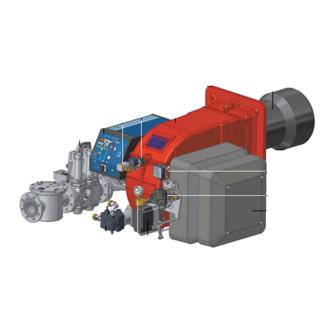
1 Control panel with startup switch
2 Gas valve group
3Cover
4Flange
5 Blast tube-Combustion head group
6 Head adjusting ring nut
7 Air tank
PART I: SPECIFICATIONS
6
Matching the burner to the boiler
To correctly match the burner to the boiler verify the necessary input and the pressure in combustion chamber are included in the bur-
ner performance curve; otherwise the choice of the burner must be revised consulting the burner manufacturer.
Burner model identification
Burners are identified by burner type and model. Burner model identification is described as follows.
Specifications
Type P72 Model M-. MD. S. RU. VS. 8. 50. ES.
(1) (2) (3) (4) (5) (6) (7) (8) (9)
(1)BURNER TYPE P60..VS - P72..VS - P73..VS
(2)FUEL M - Natural gas
(3)OPERATION PR - Progressive MD - Fully modulating
(4)BLAST TUBE S - standard
(5)DESTINATION COUNTRY * - see data plate
(6)BURNER VERSION VS - Short flameDragó
(7)EQUIPMENT
0 = 2 Gas valves
1 = 2 Gas valves + gas proving system
7 = 2 Gas valves+high gas pressure switch
8 =
2 Gas valves + gas proving system+high gas pressure switchl
(8)GAS CONNECTION 40 = Rp11/2 50 = Rp2 65 = DN65 80 = DN80
(9)MICRO-PROCESSOR CONTROL
ES = with no O2 trim control, with no VSD control
EO = with O2trim control, with no VSD control
EI = with no O2trim control, with VSD control
EK = with O2trim control, with VSD control
BURNER TYPE P60..VS P72..VS P73..VS
Output min. - max. kW 332 - 1100 300 - 1650 300 - 2150
Fuel Natural gas
Category see next paragraph ”Gas category”
Gas rate min - max (Stm3/h) 35 - 116 32 - 174,6 32 - 227,6
Gas pressure min.- max. mbar (see Note 2)
Power supply 400V 3N ~ 50Hz
Total power consumption kW 2 2,7 3,5
Electric motor kW 1,5 2,2 3
Protection IP40
Approx. weight kg 235 290 305
Operation Progressive Fully modulating
Gas Train 40 - -
Valves size/Gas connection 1”1/2 / Rp1”1/2 --
Gas Train 50 50 -
Valves size/Gas connection 2” / Rp2 2” / Rp2 -
Gas Train 65 65 65
Valves size/Gas connection 2”1/2 / 65 2”1/2 / 65 2”1/2 / 65
Gas Train 80 80 80
Valves size/Gas connection 3” / 80 3” / 80 3” / 80
Operating temperature °C -10 / +50
Storage Temperature °C -20 / +60
Working service * Continuous
Note1: All gas flow rates are referred to Stm3/h (1013 mbar absolute pressure, 15 °C temperature) and are valid for G20 gas (net
calorific value Hi= 34.02 MJ/Stm3).
Note2: Maximum gas pressure = 360mbar (with Dungs MBDLE.. valves)
= 500mbar (with Siemens VGD ..gas valves).
Minimum gas pressure = see gas curves.
PART I: SPECIFICATIONS
7
Overall dimensions (mm)
* La dimensión V se refiere a las dimensiones del filtro de gas, cuando no está incluido en el tren de válvulas VGD o MBC a partir de DN65
DN A AA AD B BB C CC D E F FF G GG H HH J K L M O P Q R S U V* W Z
P60 VS - 1.40 40 1185 324 16 195 314 990 362 931 619 312 225 266 225 306 153 189 500 344 M12 450 450 693 366 327 444 x 594 120
P60 VS - 1.50 50 1185 324 16 195 314 990 362 1013 701 312 225 266 225 306 153 189 500 344 M12 450 450 701 366 335 526 x 594 120
P60 VS - 1.65 65 1185 324 16 195 314 990 362 1058 746 312 225 266 225 306 153 250 500 376 M12 450 450 803 366 437 539 290 626 120
P72 VS - 1.50 50 1338 392 16 281 373 1057 381 1026 694 332 225 312 225 364 182 208 500 376 M12 450 450 719 384 335 519 x 626 155
P72 VS - 1.65 65 1338 392 16 281 373 1057 381 1216 884 332 225 312 225 364 182 455 500 573 M12 450 450 867 384 483 678 290 823 155
P72 VS - 1.80 80 1338 392 16 281 373 1057 381 1251 919 332 225 312 225 364 182 455 500 587 M12 450 450 919 384 535 710 319 837 155
P73 VS - 1.50 50 1289 392 16 232 373 1057 381 1026 694 332 225 324 225 364 182 208 500 376 M12 450 450 719 384 335 519 x 626 155
P73 VS - 1.65 65 1289 392 16 232 373 1057 381 1216 884 332 225 324 225 364 182 455 500 573 M12 450 450 867 384 483 678 291 823 155
P73 VS - 1.80 80 1289 392 16 232 373 1057 381 1251 919 332 225 324 225 364 182 455 500 587 M12 450 450 919 384 535 710 319 837 155
K
K
O
FF FF
O
FF
FF
Boiler plate drilling
M
P
GG GG
P
GG
GG
H
H
HH
HH
HH HH
Burner flange
PART I: SPECIFICATIONS
8
GAS TRAIN CONNECTION
The following diagrams show some examples of possible gas trains with the components supplied with the burner and those fitted by
the installer. The gas trains and the connection of the burner to the fuel supply line must be done in accordance with current local regu-
lations.
ATTENTION: Before executing the connections to the gas pipe network, be sure that the manual cutoff valves are closed.
PSPSH PSL
PSLPSH PS
M
M
MB-DLE
VGD
MBE
gas inlet
gas inlet
gas inlet
Legend:
1 Filter
2 Low pressure switch - PGMIN
3 Safety valve
4 Proving system pressure switch - PGCP (*optional)
5 High pressure switch PGMAX: mandatory for MBE, optional
for VGD and DMV-DLE
6 Butterfly valve
7 Upstream manual valve
8 Main burner
9 Antivibration joint (*optional)
12 MBE pressure sensor
with valves
with valves
with valves
PART I: SPECIFICATIONS
9
Performance curves
To get the input in kcal/h, multiply value in kW by 860.
Data are referred to standard conditions: atmospheric pressure at 1013mbar, ambient temperature at 15°C.Estas cifras se refieren a
condiciones estándar: a una presión atmosférica de 1013 mbar y una temperatura ambiente de 15°C.
NOTE: The performance curve is a diagram that represents the burner performance in the type approval phase or in the laboratory
tests, but does not represent the regulation range of the machine. On this diagram the maximum output point is usually reached by
adjsuting the combustion head to its “MAX” position (see paragraph “Adjusting the combustion head”); the minimum output point is
reached setting the combustion head to its “MIN” position. During the first ignition, the combustion head is set in order to find a
compromise between the burner output and the generator specifications, that is why the minimum output may be different from the
Performance curve minimum
BACK PRESSURE IN
CCOMBUSTION CHAMBER mbar
P60.. VS
kW
P72..VS
kW
BACK PRESSURE IN
CCOMBUSTION CHAMBER mbar
P73..VS
kW
0
2
4
6
8
10
12
14
200 300 400 500 600 700 800 900 1000 1100 1200
0
1
2
3
4
5
6
7
8
9
250 500 750 1000 1250 1500 1750
0
1
2
3
4
5
6
7
8
9
250 500 750 1000 1250 1500 1750 2000 2250
PART I: SPECIFICATIONS
10
Pressure in the network - gas rate curves
P60 - VS P72 - VS
P73 - VS
Caution: the gas rate value is quoted on the x-axis, the related network pressure is quoted on the y-axis (pres-
sure value in the combustion chamber is not included). To know the minimum pressure at the gas train inlet,
necessary to get the requested gas rate, add the pressure value in the combustion chamber to the value read on
the y-axis.
0
10
20
30
40
50
30 40 50 60 70 80 90 100 110 120 130
Rp 2"
DN65
0
10
20
30
40
50
60
20 70 120 170
DN65
Rp 2"
DN80
0
12,5
25
37,5
50
62,5
75
87,5
100
25 50 75 100 125 150 175 200 225 250 275
DN65
DN80
Rp 2" (50)
PART I: SPECIFICATIONS
11
MOUNTINGS AND CONNECTIONS
To get rid of the burner’s packing, follow the procedures laid down by current laws on disposal of materials
Packing
The burners are despatched wooden cages whose dimensions:
P60 VS: 1390 х870 х960 mm (L x P x H)
P72 VS - P73 VS: 1480 х950 х1110 mm (L x P x H)
Packing cases of this kind are affected by humidity and are not sui-
table for stacking. The following are placed in each packing case:
burner with gas train detached;
gasket to be inserted between the burner and the boiler;
envelope containing this manual
Fitting the burner to the boiler
To perform the installation, proceed as follows:
1 fix 4 holes on the boiler’s door, according to the
burner’s drilling plate described on paragraph
“Overall dimensions”;
2 place the gasket on the burner’s flange;
3 install the burner into the boiler;
4 fix the burner to the stud bolt, by means of the
fixing nuts, according to Fig. 1.
5 After fitting the burner to the boiler, ensure that the
gap between the blast tube and the refractory
lining is sealed with appropriate insulating material
(ceramic fibre cord or refractory cement).
Key
1 Burner
2 Fixing nut
3 Washer
4 Sealing gasket
5 Stud bolt
6 Blast tube
Fig. 1
H
PL
PART I: SPECIFICATIONS
12
Electrical wiring
To execute the electrical connections, proceed as follows:
1 remove the cover from the electrical board, unscrewing the fixing screws;
2 execute the electrical connections to the supply terminal board as shown in the attached wiring diagrams;
3 check the direction of the fan motor (see next paragraph);
4 refit the panel cover.
To execute the electrical connections, proceed as follows:
1 remove the cover from the electrical board, unscrewing the fixing screws;
2 execute the electrical connections to the supply terminal board as shown in the following diagrams,
3 check the direction of the fan motor (see next paragraph)
4 refit the panel cover.
Rotation of fan motor
After completing the electrical connection of the burner, remember to check the rotation of the fan motor. The motor should rotate in an
anti-clockwise direction looking at cooling fan. In the event of incorrect rotation reverse the three-phase supply and check again the
rotation of the motor.
Note on elecrtical supply
In the case where the power supply of the AUXILIARIES of the phase-phase burner (without a neutral), for the flame detection it is
necessary to connect the RC circuit Siemens between the terminal 2 (terminal X3-04-4 in case of LMV2x, LMV3x, LMV5x, LME7x) of
the base and the earth terminal, RC466890660. For LMV5 control box, please refer to the clabeling recommendations avaible on the
Siemens CD attached to the burner
WARNING! Respect the basic safety rules. make sure of the connection to the earthing system. do not reverse the
phase and neutral connections. fit a differential thermal magnet switch adequate for connection to the mains.
WARNING! before executing the electrical connections, pay attention to turn the plant’s switch to OFF and be
sure that the burner’s main switch is in 0 position (OFF) too. Read carefully the chapter “WARNINGS”, and the
“Electrical connections” section.
ATTENTION: Connecting electrical supply wires to the burner teminal block MA, be sure that the ground wire is
longer than phase and neutral ones.
DANGER! Incorrect motor rotation can seriously damage property and injure people.
WARNING: if the cable that connects the thermostats and the control box should be longer than 3 meters, insert a
sectioning relay following the attached electrical wiring diagram..
CAUTION: adjust the thermal cut-out according to the motor rated current value.
Key
C - Capacitor (22 nF , 250 V)
LME / LMV - Siemens control box
R - Resistor (1MΩ)
M:
- Terminal 2 (LGB, LME),
- Terminal X3-04-4 ( LMV2x, LMV3x, LMV5, LME7x)
RC466890660 - RC Siemens filter
LMV2/3... - LMV5...
M
LMV2/3.. - LMV5..
M
PART I: SPECIFICATIONS
13
GAS TRAIN CONNECTIONS
Following the "Hydraulic Schematics" section, the figure shows the components fitted by the installer.
Procedure to install the double gas valve unit: two (2) gas flanges are required; they may be threaded or flanged depending on
size
Gas Filter (if provided)
The gas filters remove the dust particles that are present in the gas, and prevent the elements at risk (e.g.: burner valves, counters and
regulators) from becoming rapidly blocked. The filter is normally installed upstream from all the control and on-off devices.
Once the train is installed, connect the gas valves group and pressure switches plugs.
WARNING: before executing the connections to the gas pipe network, be sure that the manual cutoff valves are
closed.
ATTENTION: it is recommended to mount filter and gas valves to avoid that extraneous material drops inside the
valves, during maintenance and cleaning operation of the filters (both the filters outside the valves group and the
ones built-in the gas valves).
ATTENTION: once the gas train is mounted, the gas proving test must be performed, according to the procedure
set by laws in force.
CAUTION: The direction of gas flow must follow the arrow on the body of the components mounted on the gas
ramp (valves, filters, gaskets...).
NOTE: the bellows unit, the manual cutoff valve and the gaskets are not part of the standard supply
first step: install the flanges to prevent entry of foreign bodies in the gas line
on the gas pipe, clean the already assembled parts and then install the valve
unit check gas flow direction: it must follow the arrow on the valve body
VGD20: make sure the O-rings are correctly positioned between the flanges
and the valve
In all cases:
ensure that the gaskets are correctly positioned between the flanges;
fasten all the components with screws, according to the following diagrams:
make sure bolts on the flanges are properly tightened
check that the connections of all components are leak .
CAUTION: Use seals suitable for the gas used.
WARNING: Slowly open the fuel cock to avoid breaking the pressure
regulator.
ATTENTION: it is reccomended to install the filter with gas flow parallel to the floor in order to prevent dust fall on
the safety valve during maintenance operation.
10
11 d
9
1
3
11c
11b
11a
gas supply network
Keys
1Gasfilter
3 Gas valves group
9 Bellows unit
10 Manual valve
11 Gasket(a, b, c, d)
A
BB
A
B
B
C
PART I: SPECIFICATIONS
14
MultiBloc MB-DLE - Assembling the gas train
Mounting
1 Mount flange onto tube lines: use appropriate sealing agent
2 Insert MB-DLE: note position of O rings
3 Remove MultiBloc between the threaded flanges
4 After installation, perform leakage and functional test
5 Disassembly in reverse order
osizione di montaggio
A
B
C
D
(A)
MOUNTING POSITIONS
A B
MB-DLE 405.. 412
(B) (C) (D)
MB-DLE 415.. 420
(O-Ring)
PART I: SPECIFICATIONS
15
DUNGS MBE
Components and position of pressure switches
PS pressure sensor connection to VD-R actuator and gas train
Pressure taps MultiBloc MBE
Attention: In the case of the MBE... valve, a pressure limit switch downstream of the safety valve is mandatory.
1 PGMIN minimum gas pressure switch
2 PGMIN minimum gas pressure switch (alternative
to 1)
3 PGCP leakage control gas pressure switch
4 PGMAX maximum gas pressure switch
5 Actuator with integrated pressure stabiliser
6 On-Off actuator
7 Valve body (Threaded)
8 Valve body (Flange)
On equipment versions Facile VD-R
must be installed upstream valve
3
5
1
2
4
6
8
VD-RVD-V
3
5
1
2
4
6
7
VD-RVD-V
min. 5 Ø
Ø
VD-R
VD-V
PS
1, 2, 3, 4 Sealing plug
G1/8 ISO 228
5Locking screw
For version VB-2L only:
connection for vent line
NPT 1
1, 2, 3, 5 Sealing plug
G1/8 ISO 228
4 G3/4 for system
accessories
6, 7 Sealing plug G1/4
ISO 228
8 For version VB…L
only: connection for
vent line
VB-2½L=1¼"NPT
VB-3L=1½"NPT
VB-4L=2"NPT
VB-5L=2"NPT
PART I: SPECIFICATIONS
16
Siemens VGD20.. e VGD40..
Components and position of pressure switches
Connection of actuator SKP2... to gas train
Siemens SKP2.. (pressure governor)
- Connect the reference gas pipe (TP in figure; 8mm-external size pipe supplied loose), to the gas pressure nipples placed on the gas
pipe, downstream the gas valves: gas pressure must be measured at a distance that must be at least 5 times the pipe size.
- Leave the blowhole free (SA in figure). Should the spring fitted not permit satisfactory regulation, ask one of our service centres for a
suitable replacement.
- D: pressure adjustment spring seat
version with SKP2 (built-in pressure stabilizer)Siemens VGD../VRD.. SKPx5 (Auxiliary-optional micro
switch)Gas valve
If the auxiliary microswitch (POC) is required, a dedicated actuator, different from the one usually supplied, must be ordered. The con-
nection is shown in the figure.
WARNING: removing the four screws BS causes the device to be unserviceable!
3
5
2
1
4
66
8
SKP15
SKP25
SKP15
SKP25
5
2
1
3
4
7
1 PGMIN minimum gas pressure switch
2 PGMIN minimum gas pressure switch (alternative
to 1)
3 PGCP leakage control gas pressure switch
4 PGMAX maximum gas pressure switch
5 Actuator with integrated pressure stabiliser
6 On-Off actuator
7 Valve body (Threaded)
8 Valve body (Flange)
min. 5 Ø
Ø
TP
BS
SA
D
SKP2
Valve
driveAG
A64
Valve
driveAG
A65
AGA64 - Valve drivePlug connection ON-OFF
AGA65 - End of strokePlug connection POC
End of stroke (POC)
The connection plug of the POC is different from that of the ON-OFF
drive
PART I: SPECIFICATIONS
17
Siemens VGD Pressure taps
Integrated proving system (burners equipped with LME7x, LMV, LDU)
Once the train is installed, connect electrically all its elements: gas valves group, pressure switches, gas proving system.
ATTENTION: once the gas train is mounted according to the diagram on Fig. 8, the gas proving test mus be perfor-
med, according to the procedure set by the laws in force.
(G 1/4") (G 1/8") (G 1/4") (G 3/4") (G 1/8") (G 1/4") (G 1/8")
Strainer
1 9 3 4 5 2 11
76 8
2V1V
10
12
4
3
9
1610
3
2
11
10
5
6
7
8
9
Legend
pi Inlet pressure
pm Pressure between valves
po Outlet pressure
PS
EV1EV2
/
EV2
EV1
PGCP
This paragraph describes the integrated proving system operation sequence:
At the beginning both the valves (EV1 and EV2) must be closed.
Test space evacuating: EV2 valve (burner side) opens and keep this position for a preset time
(td4), in order the bring the test space to ambient pressure.Test atmospheric pressure: EV2 clo-
ses and keep this position for a preset time (test time td1). The pressure switch PGCP has not to
detect a rise of pressure.
Test space filling: EV1 opens and keep this position for a preset time (td3), in order to fill the test
space.
Test gas pressure: EV1 closes and keep this position for a preset time (td2). The pressure switch
PGCP has not to detect a pressure drop down.
If all of the test phases are passed the proving system test is successful, if not a burner lockout
happens.
On LMV5x and LMV2x/3x and LME73 (except LME73.831BC), the valve proving can be parameteri-
zed to take place on startup, shutdown, or both. On LME73.831BC the valve proving is parameteri-
zed to take place on startup only.
PART I: SPECIFICATIONS
18
ADJUSTMENTS
Combustion head gas pressure curves depending on the flow rate
Curves are referred to pressure = 0mbar in the combustion head!
The curves referred to the gas pressure in the combustion head, depending on the gas flow rate, are referred to the burner properly
adjusted (percentage of residual O2 in the flues as shown in the “Recommended combustion values” table and CO in the standard
limits). During this stage, the combustion head, the gas butterfly valve and the actuator are at the maximum opening. Refer to Fig. 2,
showing the correct way to measure the gas pressure, considering the values of pressure in combustion chamber, surveyed by means
of the pressure gauge or taken from the boiler’s Technical specifications.
Fig. 2
Key
1 Generator
2 Pressure outlet on the combustion chamber
3 Gas pressure outlet on the butterfly valve
4 Differential pressure gauge
Measuring the gas pressure in the combustion head
In order to measure the pressure in the combustion head, insert the pressure gauge probes: one into the combustion chamber’s pres-
sure outlet to get the pressure in the combustion chamber and the other one into the butterfly valve’s pressure outlet of the burner. On
the basis of the measured differential pressure, it is possible to get the maximum flow rate: in the pressure - rate curves (showed on the
next paragraph), it is easy to find out the burner’s output in Stm3/h (quoted on the x axis) from the pressure measured in the combu-
stion head (quoted on the y axis). The data obtained must be considered when adjusting the gas flow rate.
NOTE: THE PRESSURE-RATE CURVES ARE GIVEN AS INFORMATION ONLY; FOR A PROPER SETTING OF THE GAS RATE,
ATTENTION: before starting the burner up, be sure that the manual cutoff valves are open and check that the pres-
sure upstream the gas train complies the value quoted on paragraph “Technical specifications”. Be sure that the
mains switch is closed.
ATTENTION: During commissioning operations, do not let the burner operate with insufficient air flow (danger of formation
of carbon monoxide); if this should happen, make the gas decrease slowly until the normal combustion values are achieved.
WARNING: NEVER LOOSE THE SEALED SCREWS! OTHERWISE, THE DEVICE WARRANTY WILL BE IMMEDIA-
TELY INVALIDATE!
IMPORTANT! the combustion air excess must be adjusted according to the in the following chart:
Recommended combustion parameters
Fuel Recommended (%) CO2Recommended (%) O2
Natural gas 9 ÷ 10 3 ÷ 4.8
TTENZIONE
TTENZIONE
1
2
4
3
PART I: SPECIFICATIONS
19
PLEASE REFER TO THE GAS METER READING.
Pressure - rate in combustion head curves
Gas Filter
The gas filters remove the dust particles that are present in the gas, and prevent the elements at risk (e.g.: burners, counters and regu-
lators) from becoming rapidly blocked. The filter is normally installed upstream from all the control and on-off devices.
GAS PRESSURE mbar
P60 - VS
Gas rate Stm3/h
P72 - VS
Gas rate Stm3/h
GAS PRESSURE mbar
P73 - VS
Gas rate Stm3/h
0
5
10
15
20
30 40 50 60 70 80 90 100 110 120
0
5
10
15
20
25 50 75 100 125 150 175 200
0
5
10
15
20
25 50 75 100 125 150 175 200 225 250
PART I: SPECIFICATIONS
20
Adjustments - brief description
The air and fuel rates adjustments must be performed at the maximum ouptput first (“high flame”): see the LMV5.. related manual..
Check that the combustion parameters are in the suggested limits.
Check the flow rate measuring it on the counter or, if it was not possible, verifying the combustion head pressure by means of a dif-
ferential pressure gauge, as described on par. “Measuring the gas pressure in the combustion head”.
Then, adjust the combustion values by setting the “gas/air” ratio” curvepoints (see the LMV5.. related manual).
Set, now, the low flame output, in order to avoid the low flame output increasing too much or that the flues temperature gets too low
to cause condensation in the chimney.
AIR FLOW AND FUEL ADJUSTMENT
(First) Start-up preliminary operations - gas supply
Recommended actions to be carried out in sequence:
1 Check the burner and all its components are installed correctly
2 Check that all electrical and mechanical parts are connected correctly
3 Check that there is water or other vector fluids in the generator
4 Check that the ventilation gates/dampers in the plant are open and the stack is free
5 Connect the gauges used to adjust and check pressures on the incoming line and on the head, air and fuel side.
6 Open the thermostatic series and the safety chain
7 Turn the main switch on the panel front with the "ON/OFF" selector to position "ON".
8 Check the phase and neutral position is correct
9 Open the manual shut-off valves slowly, in order to prevent any water hammers that might seriously damage valves and pressure
regulator
10 Check the sense of rotation of the electrical motors
11 Bleed the line, getting rid of all the air in the pipe as far as the main gas valve
12 Ensure the pressure entering the main valves is not excessive due to damage to or wrong adjustment of the line pressure regulator
13 Ensure the gas supply minimum pressure is at least equal to the pressure required by the pressure curves - burnt gas flow
Start-up procedure
1 Turn the burner on.
2 the LMV control box starts the system test cycle: the AZL display shows the System Test message; at the end of the test, it shows
the main page and the system stops (the safety chain is open) waiting for the startup enabling signal (standby - Program phase no.
12)
WARNING! During commissioning operations, do not let the burner operate with insufficient air flow (danger of
formation of carbon monoxide); if this should happen, make the fuel decrease slowly until the normal combustion
values are achieved.
WARNING! the combustion air excess must be adjusted according to the values in the following chart.
Recommended combustion parameters
Fuel Recommended (%) CO2Recommended (%) O2
Natural gas 9,0 ÷ 10 3,0 ÷ 4,8
DANGER! Venting the air from the piping must take place in safe conditions, avoiding dangerous concentrations
of fuel in the rooms. You must therefore ventilate the rooms and wait long enough for the gases to dissipate out-
side before switching on.
Setpoint 80°C
Act.value 78°C
Fuel GAS
Standby 12

This manual suits for next models

2

Other Unigas Burner manuals

Unigas HTP1030 Operating instructions

Unigas

Unigas HTP1030 Operating instructions

Unigas P61 Operating manual

Unigas

Unigas P61 Operating manual

Unigas PBY1025 Operating manual

Unigas

Unigas PBY1025 Operating manual

Unigas P75R Operating manual

Unigas

Unigas P75R Operating manual

Unigas R512A User manual

Unigas

Unigas R512A User manual

Unigas E115X User manual

Unigas

Unigas E115X User manual

Unigas LMV5 Series Operating manual

Unigas

Unigas LMV5 Series Operating manual

Unigas IDEA NG280 Service manual

Unigas

Unigas IDEA NG280 Service manual

Unigas G335A User manual

Unigas

Unigas G335A User manual

Unigas PN30 Installation and operation manual

Unigas

Unigas PN30 Installation and operation manual

Unigas G270X Operating manual

Unigas

Unigas G270X Operating manual

Unigas HP91A Operating manual

Unigas

Unigas HP91A Operating manual

Unigas E150X Operating manual

Unigas

Unigas E150X Operating manual

Unigas S10 Owner's manual

Unigas

Unigas S10 Owner's manual

Unigas PG70 Operating manual

Unigas

Unigas PG70 Operating manual

Unigas TLX115 Specification sheet

Unigas

Unigas TLX115 Specification sheet

Unigas R91A Operating manual

Unigas

Unigas R91A Operating manual

Unigas RN510 Operating manual

Unigas

Unigas RN510 Operating manual

Unigas RX1025.1 User manual

Unigas

Unigas RX1025.1 User manual

Unigas TLX83 Operating manual

Unigas

Unigas TLX83 Operating manual

Unigas K750A User manual

Unigas

Unigas K750A User manual

Unigas HR91A Reference manual

Unigas

Unigas HR91A Reference manual

Unigas RG1025 Reference manual

Unigas

Unigas RG1025 Reference manual

Unigas RX92R User manual

Unigas

Unigas RX92R User manual

Popular Burner manuals by other brands

Avantco EB100 user manual

Avantco

Avantco EB100 user manual

Members Mark GAS9670AS owner's manual

Members Mark

Members Mark GAS9670AS owner's manual

ECOSTAR NG Series Installation, operating and maintenance manual

ECOSTAR

ECOSTAR NG Series Installation, operating and maintenance manual

Maxi-matic Elite CUISINE ESB-301BF instruction manual

Maxi-matic

Maxi-matic Elite CUISINE ESB-301BF instruction manual

Ecoflam MAX GAS 170 PR manual

Ecoflam

Ecoflam MAX GAS 170 PR manual

Anderson VFC86 Operation manual

Anderson

Anderson VFC86 Operation manual

Enertech BG950 Installation and maintenance instructions

Enertech

Enertech BG950 Installation and maintenance instructions

Riello RLS 190/E Installation, use and maintenance instructions

Riello

Riello RLS 190/E Installation, use and maintenance instructions

Riello Burners RS 68/M BLU Installation, use and maintenance instructions

Riello Burners

Riello Burners RS 68/M BLU Installation, use and maintenance instructions

Town & Country Fireplaces TC42 installation instructions

Town & Country Fireplaces

Town & Country Fireplaces TC42 installation instructions

Hard Head 016913 operating instructions

Hard Head

Hard Head 016913 operating instructions

Brentwood TS-300 Operating and safety instructions

Brentwood

Brentwood TS-300 Operating and safety instructions

Enertech Bentone B 45A2.2H Installation and maintenance  instruction

Enertech

Enertech Bentone B 45A2.2H Installation and maintenance instruction

Pioneering Technologies SMARTMICRO installation instructions

Pioneering Technologies

Pioneering Technologies SMARTMICRO installation instructions

KitchenAid KBZU122VSS Installation Instructions and Use & Care Guide

KitchenAid

KitchenAid KBZU122VSS Installation Instructions and Use & Care Guide

Eastman Outdoors Revolution 37059 Instruction and safety manual

Eastman Outdoors

Eastman Outdoors Revolution 37059 Instruction and safety manual

Riello RG2 Installation, use and maintenance instructions

Riello

Riello RG2 Installation, use and maintenance instructions

baltur TBG 45 ME INSTALLATION, USE AND MAINTENANCE INSTRUCTION MANUAL

baltur

baltur TBG 45 ME INSTALLATION, USE AND MAINTENANCE INSTRUCTION MANUAL

manuals.online logo
manuals.online logoBrands
  • About & Mission
  • Contact us
  • Privacy Policy
  • Terms and Conditions

Copyright 2025 Manuals.Online. All Rights Reserved.