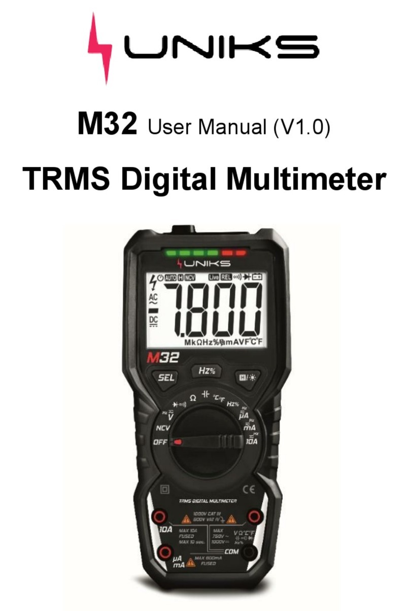
Uniks M37 User manual

1
1. Introduction ..................................................................... 3
2. Safety................................................................................. 3
2.2. Input Limits................................................................. 5
1.1. International Safety Symbols ................................. 5
1.2. Safety Category Ratings.......................................... 6
2. Description....................................................................... 8
2.1. Meter Description ...................................................... 8
2.2. Symbols Used on LCD Display.............................. 9
3. Button Function............................................................ 10
3.1. MODE and VFD Button........................................... 10
3.2. RANGE Button.......................................................... 10
3.3. Hz/% Button .............................................................. 11
3.4. HOLD/ Flashlight Button........................................ 11
3.5. Auto Power Off......................................................... 11
3.6. Low Battery Indication ........................................... 11
4. Operating Instruction .................................................. 12
4.1. AC/DC Voltage (Frequency, Duty Cycle,VFD)
Measurements ........................................................................ 12

2
4.2. MV Voltage(Frequency, Duty Cycle)
Measurements ........................................................................ 14
4.3. Frequency/Duty Cycle Measurements
(Electronic) .............................................................................. 15
4.4. AC(Frequency, Duty Cycle) Current
Measurements ........................................................................ 16
4.5. DC Current Measurements.................................... 18
4.6. Resistance Measurements.................................... 19
4.7. Diode Test ................................................................. 21
4.8. Continuity Test......................................................... 22
4.9. Capacitance Measurements.................................. 23
4.10. Temperature Measurements............................ 25
4.11. Lo Z AC/DC Voltage Measurements............... 26
5. Maintenance and Cleaning......................................... 28
6. Battery Replacement................................................... 29
7. Fuse Replacement........................................................ 31
8. Specifications................................................................ 32
8.1. Specifications........................................................... 32
8.2. General Specifications........................................... 34

3
Introduction
The meter measures AC/DC Voltage, AC/DC Current ,
Resistance,Diode Test, Continuity , Capacitance,
Frequency,Duty Cycle and Temperature .True RMS readings
provide accurate AC measurements and a Lo Z setting
eliminates errors caused by “ghost” voltages. It features a
waterproof ,rugged design for heavy duty use.and it also
offers the added convenience of a built-in LED
flashlight .Proper use and care of this meter will provide many
years of reliable service.
1. Safety
1.1. Warnings
•Read, understand and follow Safety Rules and
Operating Instructions in this manual before using this
meter.
•The meter’s safety features may not protect the user if
not used in accordance with the manufacturer’s
instructions.
•Keep fingers away from the metal probe tips when
taking measurements.

4
•Before changing functions using the selector switch,
always disconnect the test leads from the circuit under
test.
•Comply with all applicable safety codes. Use approved
personal protective equipment when working near live
electrical circuits - particularly with regard to arc-flash
potential.
•Use caution on live circuits. Voltages above 30 V AC
rms, 42 V ac peak, or 60 V dc pose a shock hazard.
•Do not use if the meter or test leads appear damaged.
•Verify operation before using meter by measuring a
known live voltage.
•Do not use the meter in wet or damp environments or
during electrical storms.
•Do not use the meter or near explosive vapors, dust or
gasses.
•Do not use the meter if it operates incorrectly.
Protection may be compromised.
•Do not operate meter while Low Battery warning is on.
Replace batteries immediately.
•Do not apply voltage or current that exceeds the
meter’s maximum rated input limits.

5
1.2. Input Limits
Function
Maximum Input
Voltage AC or DC
600V AC /DC
Lo Z
600V AC/DC
Frequency,Resistance,Capa
citance,Continuity, Diode
Test,Temperature
600V AC/DC
10A Current AC or DC
10A/600V fast acting
Fuse
1.1. International Safety Symbols
This symbol adjacent to another symbol, terminal or
operating device indicates that the operator must
refer to an explanation in the Operating
Instructions to avoid personal injury or damage to
the meter.
This symbol adjacent to one or more terminals
identifies them as being associated with ranges
that may, in normal use, be subjected to
particularly hazardous voltages. For maximum
safety, the meter and its test leads should not be
handled when these terminals are energized.
Double insulation
Indicates the terminal(s) so marked must not be
connected to a circuit where the voltage with
respect to earth ground exceeds the maximum
safety rating of the meter.
MAX
600V

6
This WARNING symbol indicates a
potentially hazardous situation, which if
not avoided, could result in death or
serious injury.
This CAUTION symbol indicates a
potentially hazardous situation, which if
not avoided, may result damage to the
product.
1.2. Safety Category Ratings
Category
Rating
Brief
Description
Typical Applications
CAT II
Single phase
receptacles and
connected
loads
•Household
appliances, power
tools
•Outlets more than
30ft (10m) from a
Cat III source
•Outlets more than
60ft (20m) from a
Cat IV source
CAT III
Three phase
circuits and
single phase
lighting circuits
in commercial
buildings
•Equipment in fixed
installations such
as 3-phase motors,
switch gear and
distribution panels
WARNING
CAUTION

7
•Lighting circuits in
commercial
buildings
•Feeder lines in
industrial plants
•Any device or
branch circuit that
is close to a Cat III
source
The measurement category (CAT) rating and voltage
rating is determined by a combination of the meter, test
probes and any accessories connected to the meter and
test probes. The combination rating is the LOWEST of any
individual component.
WARNING: Operation is limited to CAT II
applications when the insulated tips are removed
from one or both test probes. Refer to Input Limits
section in this manual for maximum voltage ratings.

8
2. Description
2.1. Meter Description
1. LCD display
2. RANGE button
3. MODE and VFD button
4. Rotary function switch
5. 10A input jack
6. COM input jack
7. Positive input jack
8.HOLD and Flashlight
button
9.Hz% button
10.Flashlight

9
2.2. Symbols Used on LCD Display
V
Volt
k
kilo (103)
A
Ampere
OL
Overload
F
Farad
(Capacitance)
Low battery
Alternating
current
AUTO
Auto ranging
Direct current
HOLD
Display Hold
-
Minus Sign
Hz
Hertz (frequency)
Ω
Ohm
%
Duty Cycle
continuity
°C
Degrees Celsius
Diode Test
°F
Degrees
Fahrenheit
n
nano (10-9)
Auto Power OFF
µ
micro (10-6)
VFD
Filter
m
milli (10-3)
Loz
Low impedance

10
3. Button Function
3.1. MODE and VFD Button
Press the MODE key to select AC/DC Voltage ,AC/DC
Current,Ohms, Diode Test, Continuity or Capacitance,
Temperature.
When the AC voltages,press the MODE key for >2
second to turn on or off the VFD function .
3.2. RANGE Button
When the meter is first turned on, it automatically goes
into Auto Ranging. This automatically selects the best range
for the measurements being made and is generally the best
mode for most measurements. For measurement situations
requiring that a range be manually selected, perform the
following:
1. Press the RANGE button. The “AUTO” display indicator
will turn off.
2. Press the RANGE button to step through the available
ranges until you select the range you want.
3. Press and hold the RANGE button for 2 seconds to exit the
Manual Ranging mode and return to Auto Ranging.

11
3.3. Hz/% Button
Used to select Frequency or Duty Cycle when the
meter is set to AC voltage、Frequency or AC Current.
3.4. HOLD/ Flashlight Button
Press the HOLD key to turn on or off the HOLD
function .
Press the Flashlight key for >2 second to turn on or off the
Flashlight function .
3.5. Auto Power Off
The auto off feature will turn the meter off after 15
minutes. To disable the auto power off feature, hold down
the MODE button and turn the meter on.
3.6. Low Battery Indication
The icon will appear in the lower left corner of the
display when the battery voltage becomes low. Replace the
battery when this appears.

12
4. Operating Instruction
4.1. AC/DC Voltage (Frequency, Duty
Cycle,VFD) Measurements
WARNING: Observe all safety precautions when
working on live voltages.
CAUTION: Do not measure voltages if a
motor on the circuit is being switched
ON or OFF. Large voltage surges may
occur that can damage the meter.
1. Set the rotatory function switch to the position.
2. To select AC or DC voltage, press the MODE button
until The “ ” (AC) or “ ” (DC) symbol appears on
the LCD display.
3. Insert the black test lead into the COM input jack and
the red test lead into the Positive input jack.
4. Touch the test lead probes to the circuit under test. If
measuring DC voltage, touch the red test lead to the

13
positive side of the circuit and the black test lead to the
negative side of the circuit.
5. Read the voltage on the LCD display.
6. When the AC voltages ,Press the Hz/% button to
indicate “Hz”.
7. Read the frequency in the display.
8. Press the Hz/% button again to indicate “%”.
9. Read the % of duty cycle in the display.
10. When the AC voltages ,press and hold the MODE key
for >2 second to indicate “VFD”.
11. Read the voltage in the display.
12. To exit VFD mode press and hold the MODE key for >2
second.

14
4.2. MV Voltage(Frequency, Duty Cycle)
Measurements
CAUTION: Do not measure mV voltages if a
motor on the circuit is being switched ON or
OFF. Large voltage surges may occur that
can damage the meter.
1.Set the function switch to the mV position.
2.Press the MODE button to indicate DC or AC .
3.Insert the black test lead banana plug into the negative
COM jack. Insert the red test lead banana plug into the
positive input jack.

15
4.Touch the black test probe tip to the negative side of the
circuit.
Touch the red test probe tip to the positive side of the
circuit.
5.Read the mV voltage in the display.
6.When the AC voltages ,press the Hz/% button to indicate
“Hz”.
7. Read the frequency in the display.
8. Press the Hz/% button again to indicate “%”.
9. Read the % of duty cycle in the display.
4.3. Frequency/Duty Cycle Measurements
(Electronic)
WARNING: Observe all safety
precautions when working on live voltages.
1. Set the rotary function switch to Hz/% position .

16
2. Insert the black lead banana plug into the negative COM
jack and the red test lead banana plug into the Positive
input jack.
3. Touch the test probe tips to the circuit under test.
4.Read the frequency on the display.
4. Press the HZ/% button again to indicate “%” on the
display.
6.Read the % of duty cycle on the display.
4.4. AC(Frequency, Duty Cycle) Current
Measurements
WARNING: Observe all safety precautions when
working on live circuits.Measurements in the 10A
range should be limited to 30 seconds maximum
every 15 minutes.
1. For current measurements up to 10A AC, set the rotary
function switch to the 10A position.

17
2. Insert the black test lead into the COM input jack and
Insert the red test lead into the 10A input jack .
3. Remove power from the circuit under test, then open up
the circuit at the point where you wish to measure current.
4. Touch the black test probe tip to the neutral side of the
circuit.
Touch the red test probe tip to the “hot” side of the circuit.
5. Apply power to the circuit.
6. Read the current on the LCD display.
7. Press the Hz/% button to indicate “Hz”.
8. Read the frequency in the display.
9. Press the Hz/% button again to indicate “%”.
10. Read the % of duty cycle in the display.

18
4.5. DC Current Measurements
WARNINGS: Observe all safety precautions
when working on live circuits. Measurements in the
10A range should be limited to 30 seconds maximum
every 15 minutes.
1. For current measurements up to 10A DC, set the rotary
function switch to the 10A position.

19
2.Insert the black test lead into the COM input jack and
Insert the red test lead into the 10A input jack .
3.Remove power from the circuit under test, then open up
the circuit at the point where you wish to measure current.
4.Touch the black test probe tip to the neutral side of the
circuit.
Touch the red test probe tip to the “hot” side of the circuit.
5.Apply power to the circuit.
6.Read the current on the LCD display.
4.6. Resistance Measurements
WARNING: Never test resistance on a live circuit.
1. Set the rotary function switch to the // CAP
position.
2. Press the MODE button until the “”symbol appears on
the LCD display.
3.Insert the black test lead into the COM input jack and the
red test lead into the Positive input jack.

20
4.Touch the test lead probes to the component under test. If
the component is installed in a circuit, it is best to disconnect
one side before testing to eliminate interference with other
devices.
5.Read the resistance in on the LCD display.
Table of contents
Other Uniks Multimeter manuals