Page 7
TPCMQ48 SERIES
INSTALLATION & OPERATING MANUAL
Manual No. tpcmq48-4 tpcmq48-man-rev4-0116.indd
7.0 MODULE SPECIFICATIONS
The following specications are typical at 25°C unless otherwise noted.
OUTPUT SPECIFICATIONS
Total Output Power, Continuous, Max................see table page 1
Voltage Adjustment Range, Min. ........................... -25% to +10%
Total Regulation1...................................................................2.0%
Total Regulation, Standby Supply ........................................5.0%
Ripple & Noise, Pk-Pk2......................................................200mV
Voice Band Noise.........................................................<32dBrnC
Dynamic Response3...........................................................300µS
Temperature Coecient ..............................................±0.02%/°C
Minimum Load..........................................................................0A
Current Limit................................................105% Rated Current
Overload Protection...............................................Auto Recovery
Overvoltage Protection................................... Latched Shutdown
Remote Sense............................................Up to 0.25V Per Wire
Current Share...........................................±10% Full Load Rating
Standby Output..........................................................+5V, 250mA
Output Power Good Signal...........................................Logic Low
Input Power Fail Signal................................................Logic High
Inhibit............................................................................Logic Low
Enable ..........................................................................Logic Low
Thermal Warning.........................................................Logic High
INPUT SPECIFICATIONS
Input Voltage Range.................................................... 40-60VDC
Inrush Current Limiting..................................................10A Peak
Input EMI Filter...............................................................Standard
Analog Voltage Adjust......................................................0 to +5V
Input Immunity, Conducted
Fast Transients, Line-Line.....................±500V (EN61000-4-4)
Surges, Line-Line ..................................±500V (EN61000-4-5)
Surges, Input Ground............................±500V (EN61000-4-5)
Input Protection 12/24Vout..............................Internal Fuse, 30A
48Vout .................. requires external protection
GENERAL SPECIFICATIONS
Eciency 4
12/24Vout ................................................82-88% at Full Load
48Vout .................................................up to 90% at Full Load
Switching Frequency..........................................210kHz Nominal
Isolation, Class I, min.5
Input-Output..............................................................2121VDC
Input-Ground ............................................................1000VDC
Output-Ground.........................................................................
100VDC..............................................................................MTBF
(Bellcore)...............................................................200,000 Hours
Safety Standards....................UL60950-1, CSA22.2 No.60950-1
EN60950-1
ENVIRONMENTAL SPECIFICATIONS
Operating Temperature.............................-20°C to 70°C Ambient
Derating....................................................2.5%/°C, 50°C to 70°C
Storage Temperature............................................-40°C to +85°C
Cooling ................................................Integral Ball Bearing Fans
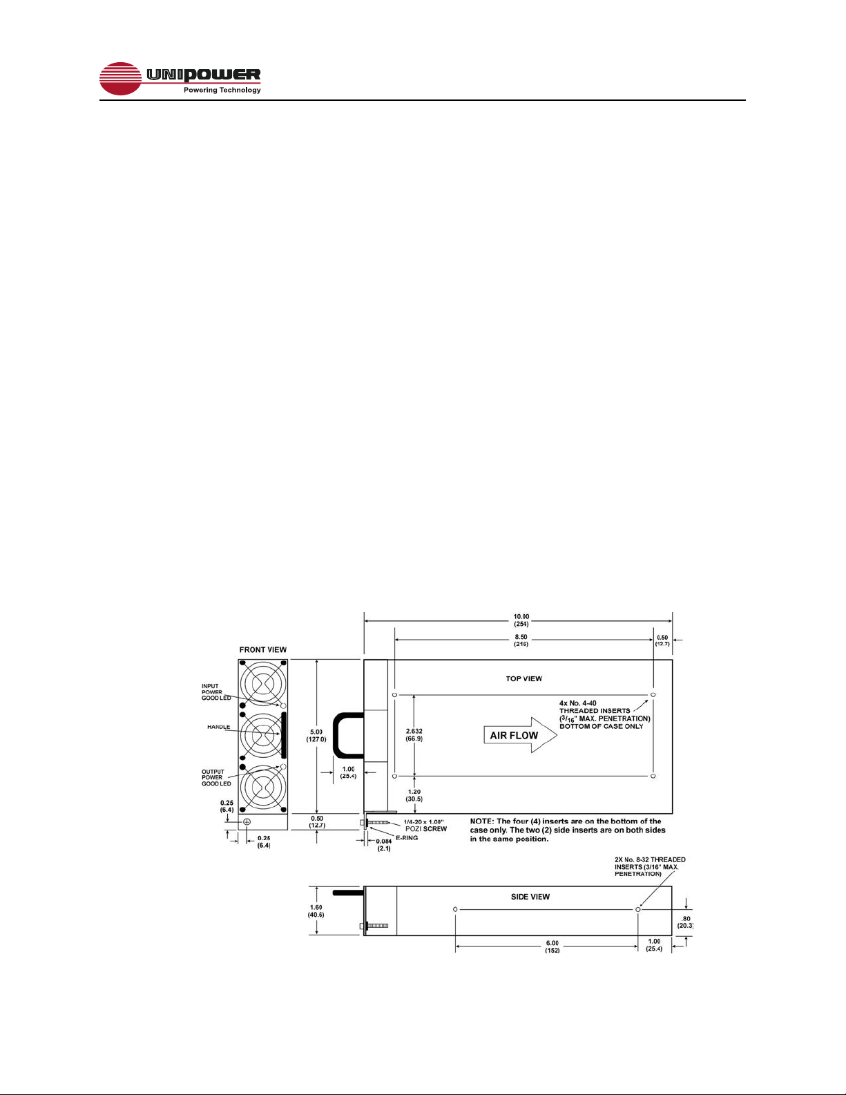
PHYSICAL SPECIFICATIONS
Case Material, Module & Rack/Shelf............................Aluminum
Dimensions, Inches(mm)
Module.................................................1.6 H x 5.0 W x 10.0 D
(40.6 x 127 x 254)
Rack/Shelf....................................1.72H x 19.00 W x 11.56 D
(44 x 483 x 294)
Weight
Module....................................................... 3.15 lbs. (1.43 kg.)
Rack/Shelf.................................................4.15 lbs. (1.88 kg.)
NOTES:
1. No load to full load, including line regulation and load regulation.
2. Whichever is greater. 20MHz bandwidth. Measure with 0.1µF ceramic and 10µF
tantalum capacitors in parallel across the output.
3. <4% deviation recovering to within 1% for 25% load change.
4. Typical eciency is at low end of range for 12V output and at high end of range
for 24V output.
5. Input-output isolation gure is for isolation components only. 100% production
Hipot tested input to ground.
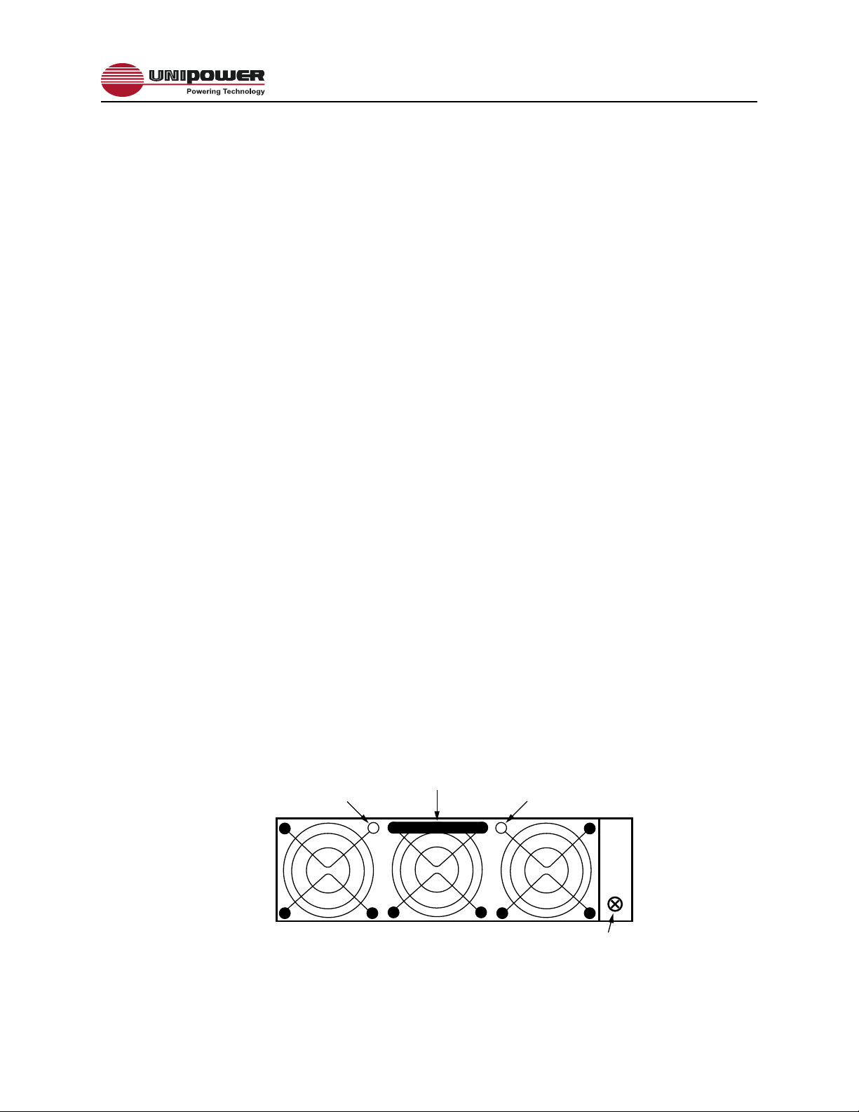
8.0 FRONT PANEL DESCRIPTION
GOOD
GOOD
Figure 2 - Front Panel View