United CoolAir SCPAC5G AS Series User manual

PORTABLE HORIZONTAL HEATING UNITS
INSTALLATION OPERATION AND MAINTENANCE MANUAL
50–60–150 kW
PHH50–150G3
REV — 6/15/20
Serial Number ����������������������������

Subject to change without notice. 2PHH50–150G3
REV — 6/15/20
IDENTIFICATION OF YOUR UNIT
The Data Tag contains important information
on how identify your United CoolAir Unit.
See Figure 1 for more information on locating tag.
MODEL NO. SCPAC5GxAS�3�24�16
SERIAL NUMBER 1610057
VOLTS 460 PHASE 3 CYCLE 60
COMP. LRA 351 EA QTY 2 RLA 53.6 EA
EVAP. MOTOR HP 15.0 FLA 35
COND. MOTOR HP 3.0 EA QTY 2 RLA 8.6 EA
ELEC. HEATER KW 15
MCA 25.8
MOP 30
FACTORY CHARGE R-410A 46 lb 0oz CKT1
46 lb 0oz CKT2
TEST PRESS. HISIDE 500 PSIG - LOSIDE 250 PSIG
COMPRESSOR MOTOR AND FAN ARE THERMALLY PROTECTED
USE COPPER CONDUCTORS ONLY.
EXT. STATIC PRESS - 0.1 TO 1.0 IN. WC.
MAX OUTPUT AIR TEMP. 200 DEG. F OR LESS
MIN. CLEARANCE TO COMBUSTIBLE SURFACES - 0 IN
9CA-6242
UNITED COOLAIR CORPORATION
YORK, PA
SAMPLE

Subject to change without notice. 3PHH50–150G3
REV — 6/15/20
WARNING: HIGH VOLTAGE – DISCONNECT POWER BEFORE SERVICING
DISCONNECT POWER
Failure to disconnect power before
servicing could lead to severe
personal injury or death.
RE-CONNECT ALL GROUNDS
All parts of this product capable of conducting electrical current
are grounded. If grounding wires, screws, straps, clips, nuts,
or washers used to complete a path to ground are removed for
servicing, they must be reconnected at their original location.
TABLE OF CONTENTS
IDENTIFICATION OF YOUR UNIT ...........................................................2
SPECIFICATIONS – 50 kW Horizontal Portable Heating Unit ....................................4
SPECIFICATIONS – 60 kW Horizontal Portable Heating Unit ....................................4
SPECIFICATIONS – 150 kW Horizontal Portable Heating Unit ...................................4
INSPECTION............................................................................5
MOUNTING.............................................................................5
INSTALLATION..........................................................................5
OPERATING INSTRUCTIONS ..............................................................6
CONTROLS ............................................................................6
UNIT COMPONENTS .....................................................................6
MAINTENANCE .........................................................................7
TROUBLESHOOTING GUIDE ..............................................................8
APPENDIX – DRAWINGS AND SCHEMATICS
Product Drawing .........................................................CA11469D
Wiring Diagram ........................................................CA7730T4-1A

Subject to change without notice. 4PHH50–150G3
REV — 6/15/20
SPECIFICATIONS – 50 kW Horizontal Portable Heating Unit
SPECIFICATIONS – 60 kW Horizontal Portable Heating Unit
SPECIFICATIONS – 150 kW Horizontal Portable Heating Unit
208 - 230/3/60 460/3/60 575/3/60
KW 60
Current Draw 149.9 75.7 60.5
Motor HP 2
FLA 5.8 2.9 2.4
MCA 194.6 98.25 78.6
MOP 225 100 80
Drawing Number CA11469D
*Readings are dependent upon ambient conditions; numbers listed are approximate
208 - 230/3/60 460/3/60 575/3/60
KW 150
Current Draw - 188.3 150.6
Motor HP 15
FLA - 17.5 13.5
MCA - 257.3 205.1
MOP - 300 225
Drawing Number CA8875
*Readings are dependent upon ambient conditions; numbers listed are approximate
208 - 230/3/60 460/3/60 575/3/60
KW 50
Current Draw 131.2 56.6 45.2
Motor HP 2
FLA 5.8 3 2.5
MCA 171.6 74.4 59.7
MOP 175 75 70
Drawing Number CA7730R
*Readings are dependent upon ambient conditions; numbers listed are approximate

Subject to change without notice. 5PHH50–150G3
REV — 6/15/20
INSPECTION
Upon receiving the unit, inspect for structural,
interior, and exterior damage that may have
occurred during transit. Report any damage to the
carrier and le a damage claim immediately.
MOUNTING
The unit is a self-contained horizontal heating
system. It should be mounted on a at level
surface. The units may be double stacked for
shipping and storage.
NEVER FORK LIFT OR CRANE LIFT DOUBLE
STACKED UNITS. ALWAYS FORKLIFT OR
CRANE A SINGLE UNIT AT A TIME.
INSTALLATION
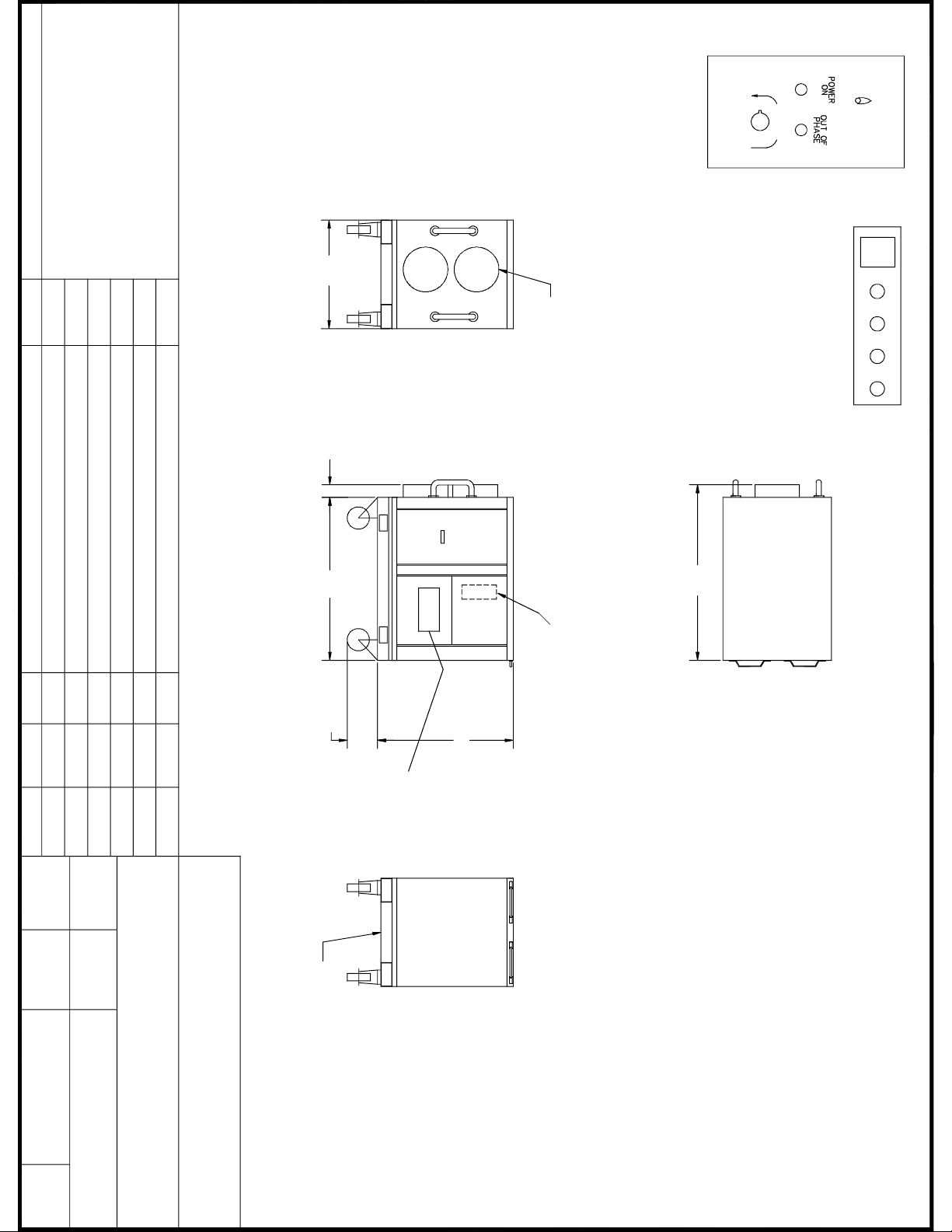
The standard conguration of the horizontal
heating units are shown in Figure 1. The unit will
be shipped as a single packaged unit.
Figure 2 – Horizontal Heater
1. Move the unit to the location of operation
using the forklift pockets located in the base
of the unit. DO NOT STACK the Heaters. Use
spreader bars when using a crane to lift the
heater.
2. Power must be supplied to the unit from a
power source (commercial or generator)
via connecting power wires or cables which
terminate in a Camlock tting. Check the main
power source being utilized to ensure it has
the capability to deliver the required power to
the unit.
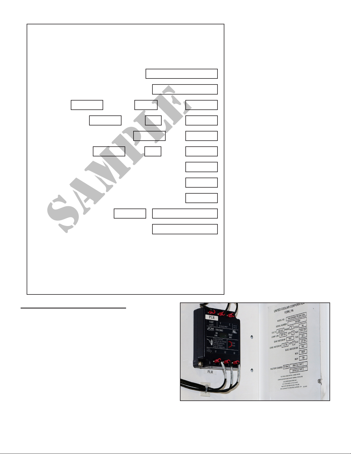
3. Route power cables with Color Coded quick-
connect Camlock Plugs to the unit from the
main power supply. Attach the power cables
to the color coded Camlock receptacles. Refer
to Figure 3 – Camlock Receptacles / Circuit
Breaker / Data Label for location. Make sure
the power supplied to the unit matches the
power requirements for this unit. Refer to
the Electrical Data Label provided on the unit
or the specications section of this manual
for power requirements. The Color Coded
Camlock input connectors have spring loaded
metal covers. Simply pull back the cover, push
the Camlock plug into the Camlock receptacle
and twist ¼ turn until the connector locks.
Figure 2 – Camlock Receptacles /
Circuit Breaker / Data Label
4. The unit has a circuit breaker to disconnect
power at the unit up to the point of the unit’s
circuit breaker. Refer to Figure 3 above for
location. Make sure the unit’s circuit breaker
is in the OFF position before applying power
to the unit.
CAUTION: WHEN POWER IS ON AT THE MAIN
POWER SOURCE AND THE UNIT’S CIRCUIT
BREAKER IS OFF, BE CAREFUL BECAUSE
Camlock Receptacles
Data Label
Circuit
Breaker

Subject to change without notice. 6PHH50–150G3
REV — 6/15/20
THERE IS STILL POWER AT THE UNIT’S
CIRCUIT BREAKER.
5. The unit has a built in Selector Switch (SS)
OFF/FAN/Heat in the control panel. Make
sure the SS is set to the OFF position before
applying power to the unit. See Figure 4 –
Control Panel for reference.
Figure 3 – Control Panel
6. Install the proper size exible supply and
return ducting to the unit in as straight a
manner as possible. Avoid making excessive
turns or turns greater than 45° as this will
increase restriction on the blower and cause
a decrease in total air ow. Excessive bends
or kinks may cause the heaters to short cycle.
CAUTION: USE HIGH TEMPERATURE DUCTS
RATED FOR 325°F .
CAUTION: Before applying power make
certain the unit is connected to Earth ground.
OPERATING INSTRUCTIONS
Switch the main power disconnect at the power
supply to the ON position. Internal wiring connects
the input power at the unit to a circuit breaker on
board the unit, which also serves as a service
disconnect switch for the unit. Switch the unit’s
circuit breaker to the “ON” position to supply
power to the unit.
Once the power is “ON”, the Power LED should
illuminate. If the Power LED is illuminated, the unit
is ready for operation. If not, check the voltage
being supplied to the unit at the main power
source. Disconnect (turn OFF) the unit’s circuit
breaker and the main power at the power source
when checking for voltage.
CONTROLS
Blower Control:
When the Circuit Breaker (CB) is in the ON
position, switching the SS to the ON position will
start the supply air blower.
Placing the SS to the heat position will energize
the heater banks. The thermostat senses the
Return Air (RA) and switches heaters on or off to
maintain setpoint.
UNIT COMPONENTS
Heater Time Delays
The unit is manufactured with internal time delays
to protect the system from overloading the supply
power with a large inrush all at the same time.

Subject to change without notice. 7PHH50–150G3
REV — 6/15/20
Panel Removal
The removable panels are secured with ¼ Turn
latches that are unlatched using a 3/16” Slotted
Standard screwdriver.
Heaters
The unit is a multiple stage heating system
supplied with a total of three heating banks. Each
heater bank is a tubular construction.
Thermostat
Each unit is supplied with a main thermostat that
is adjusted on the front of the control panel to
maintain the temperature within the enclosure
being controlled.
Discharge Air Thermostat
The unit is supplied with a discharge air thermostat.
The discharge air thermostat is located internal
to the control box directly behind the unit’s main
Thermostat and System ON/OFF Switch. This
switch prevents the discharge air temperature
from exceeding 160°F.
System ON/OFF Switch
Each unit is supplied with a Selector Switch (SS)
to turn ON/OFF the airow and heating to the
space being conditioned.
Heater High Limit Switches
The unit has two 180°F heater high limit cutout
switches designed to shut the heaters down if the
temperatures rise above 180°F.
MAINTENANCE
Bearings
The Blower Motor and Blower Assembly bearings
are permanently lubricated and require no
lubrication.
Belts
The supply air blower is belt driven and are
provided with adjustable sheaves to change the
speed of the air ow (if required). The drive belts
should be examined periodically for wear and
for correct tension. If the belts are too tight it can
cause excessive motor and blower bearing wear
and a loose belt can cause belt slippage. When
the belts are pressed in, midway between the
pulley and the sheave, resulting in approximately
1” of movement, the belts are tensioned properly.
Belt tension can be adjusted by means of the
adjusting bolt, which requires loosening a nut to
move the motor to change belt position.
Filter Maintenance
The unit is shipped with cleanable lter(s) installed
in the return air section. The Panel Door under
the Control Section or side opposite the Control
Section must be removed to access the lters for
cleaning. Check lters every few weeks to verify
that the lters are clean and free of dust or dirt.
After a period of use, dirt, lint, and the original water
soluble adhesive coating are easily removed by
simply ushing the lter in a stream of luke-warm
water.
Apply a new coating of adhesive, such as RP Super
Filter Coat, to restore the lter characteristics.

Subject to change without notice. 8PHH50–150G3
REV — 6/15/20
TROUBLESHOOTING GUIDE
WARNING: BE AWARE OF HIGH POWER SITUATIONS WHILE TROUBLESHOOTING. THERE ARE
ALSO MOVING BELTS, BLOWERS, AND MOTORS WHILE POWER IS CONNECTED
TO THE UNIT. WHEN REACHING INTO ANY OF THE UNIT SECTIONS TO MAKE
ADJUSTMENTS TO THE UNIT. PLEASE DISCONNECT POWER FROM THE UNIT.
Problem Cause Description
Control is erratic Loose wiring connections Check wiring for loose connections, screw terminals, or lugs
Broken V-Belt Replace V-Belt.
Circuit Breaker
Turn ON Circuit Breaker (CB5).
Check for tripped Circuit Breaker (CB5).
Replace if defective.
Check operational current (amperage).
System ON/OFF Switch Check to see System ON/OFF Switch is turned ON.
No Heating
Thermostat Setting Check thermostat setting and increase if required.
Air Switch Check adjustment on air switch.
Test and replace defective air switch.
Circuit Breakers
Turn on Heating Circuit Breakers (CB1 – CB4).
Check for tripped Heat Circuit Breakers (CB1 – CB4).
Replace if defective.
Check operational current (amperage).
Power Light Light OFF
No Power to the unit. Check Voltage at the Main Power Supply.
Check Control Panel Fuses F1, F2, F3.
Check LP1 to see if it’s burned out.
System short cycles
Reduced airow
Increase the airow by disconnecting power and closing the
motor sheave a turn or two. Verify motor amps is under the
nameplate rating.
Check for kinks or excessive turns in the ducting.
Check for dirty air lters and clean as necessary
Check for broken or loose v-belts.
Discharge Air Thermostat Check to see if the Discharge Air Thermostat is set between
150°F and 160 °F.

RIGHT SIDE VIEW
TOP VIEW
REAR VIEW
FRONT VIEW
ACCESS
EVAPORATOR
SECTION
CONTROLS BEHIND
HINGED PANEL
SEE DETAIL A
55.0
41.5
4.0 51.0
34.0
DETAI L A''
TEMP
G R
INCREASE
HEAT
FAN
OFF
10.0
SEE
DETAIL B
STANDARD PANEL
SUBJECT TO CHANGE WITHOUT NOTICE
ALL PROPRIETARY RIGHTS IN THIS
PURCHASE ORDER/ DRAWING ARE
RESERVED. NO PERMISSION IS
GRANTED TO REPRODUCE THIS
DRAWING IN PART OR IN WHOLE,
OR DISCLOSE ANY OF THE INFOR-
MATION UPON IT TO OTHERS WITHOUT
WRITTEN PERMISSION FROM
UNITED COOLAIR CORP.
SHT: 1 OF 1
REV.
-NEW
DESCRIPTION DATE
03/13/09
BY
JTP
ECN#
YORK, PA.
JTP
01/18/12
DATE:
DWN BY:
TITLE:
DATE:
APP. BY:
D
REV. LEV.
NOT TO SCALE
CA11469
DWG. NO:
15-60 KW ELECTRIC
HEAT UNIT
WITH 14" OR 16" DUCT CONNECTIONS
SCALE:
U.S.A.
UNITED COOLAIR CORP.
SUPPLY
RETURN
14" OR 16" DIA
LIFTING POD
(OPTIONAL)
A REVISED DIMENSIONS
JTP
03/24/09
B DELETED REVISIONS MADE IN REV A
MJT
11/12/09
CAMLOCK PANEL - STANDARD
TED AI L ''B
CB
C CHANGED KW AND ADDED DUCT NOTE
JTP
01/18/12
D REVISED KW RANGE AND FEATURES
JTP
11/04/13
Table of contents
Popular Heating System manuals by other brands

Hallowell
Hallowell Acadia i Series installation manual

Roca
Roca LAIA GTI Operating, cleaning and maintenance instructions

LG
LG Multi V Water 5 manual

Steffes
Steffes Comfort Plus Commercial 6140 Owner's and installer's manual

Tecnoclima
Tecnoclima SR-UT Series TECHNICAL INFORMATION ASSEMBLY, USE AND MAINTENANCE INSTRUCTIONS

Aqua-Hot
Aqua-Hot 400D installation manual

Thermal Intelligence
Thermal Intelligence BASECAMP Operator's manual

National Comfort Products
National Comfort Products CPE Series installation manual

Reversomatic
Reversomatic Deluxe ECM Series Installation and operating instructions

Vents
Vents VUT V EC A11 Series user manual

AERMEC
AERMEC URX CF Series user manual

Vira
Vira ViRATOP ST Installation and operation instructions