United Electric Controls UE VANGUARD WirelessHART TCD60HXY User manual

WirelessHART®Toxic & Combustible Gas Detector
P/N: TCD60HXY
Installation and Maintenance Instructions
IM_TCD60-01
11/05/2021

WirelessHART Toxic & Combustible Gas DetectorIM_TCD60-01
www.ueonline.com/vanguard
i
United Electric Controls provides these installation and maintenance instructions for the UE Vanguard Wire-
lessHART toxic & combustible gas detector solely. The end-user is responsible for maintaining the Vanguard
WirelessHART toxic & combustible gas detector in full, operational condition. All warnings must be thor-
oughly read, understood and followed.
Misuse of this device and failure to adhere to all warnings could result in:
• the device not performing as intended,
• risk of explosion,
• risk of losing consciousness or death.
The following symbols are used within this document:
International Hazard Warning symbol. Directions require strict adherence.
International Toxic Hazard symbol. Exposure may lead to loss of consciousness or death.
International Flammable Material Hazard symbol. Exposure to ammable materials in closed areas
may lead to explosion, loss of consciousness or death.
United Electric Controls reserves the right to change published specications and designs without prior
notice.
United Electric Controls Co.
180 Dexter Avenue
Watertown, MA
02472, USA
Telephone: +1 617 926-1000
Fax: +1 617 926-2568
Email: [email protected]
Web: www.UEonline.com
8

WirelessHART Toxic & Combustible Gas Detector IM_TCD60-01
www.ueonline.com/vanguard
ii
Please read all instructional literature carefully and thoroughly before starting
Table of Contents
1.0 General
1.1 Device Overview.........................................................................1-2
1.2 Device Packaging.......................................................................3
1.3 Device Approvals.......................................................................4-5
2.0 Installation
2.1 Battery Installation......................................................................6-7
2.2 Sensor Installation...................................................................... 8-9
2.3 Sensor Placement Considerations........................................ 9-10
2.4 Sensor Cross Sensitivity............................................................10
2.5 Classied Area Installation.......................................................11
2.6 Field Mounting............................................................................ 11-16
2.7 Antenna Placement Considerations.....................................17
2.8 Network Conguration..............................................................17-20
3.0 Operation
3.1 Normal Operation.......................................................................21
3.2 Sensor Calibration & Bump Test.............................................22-24
3.3 Programming Mode...................................................................25-29
4.0 Field Replacement
4.1 Sensor Replacement..................................................................30
4.2 Battery Replacement.................................................................31
5.0 Troubleshooting Guide
5.1 Hardware.................................................................................... . 32
5.2 Wireless Communication.........................................................33
6.0 Dimensional Drawings....................................................................34
7.0 Appendix
7.1 List of Figures................................................................................35
7.2 List of Tables..................................................................................36
7.3 List of Graphs................................................................................36
7.4 List of Device Warnings (French Language)......................37-40

WirelessHART Toxic & Combustible Gas Detector
IM_TCD60-01
www.ueonline.com/vanguard
1
1.0 GENERAL
This device is for monitoring and communicating gas concentration levels for data collection or
record keeping and does not provide alarm signals.
Misuse of this device may cause explosion and/or personal injury. These instructions must be
thoroughly read and understood prior to installation of the device.
The end-user is responsible for maintaining the device in full, operational condition.
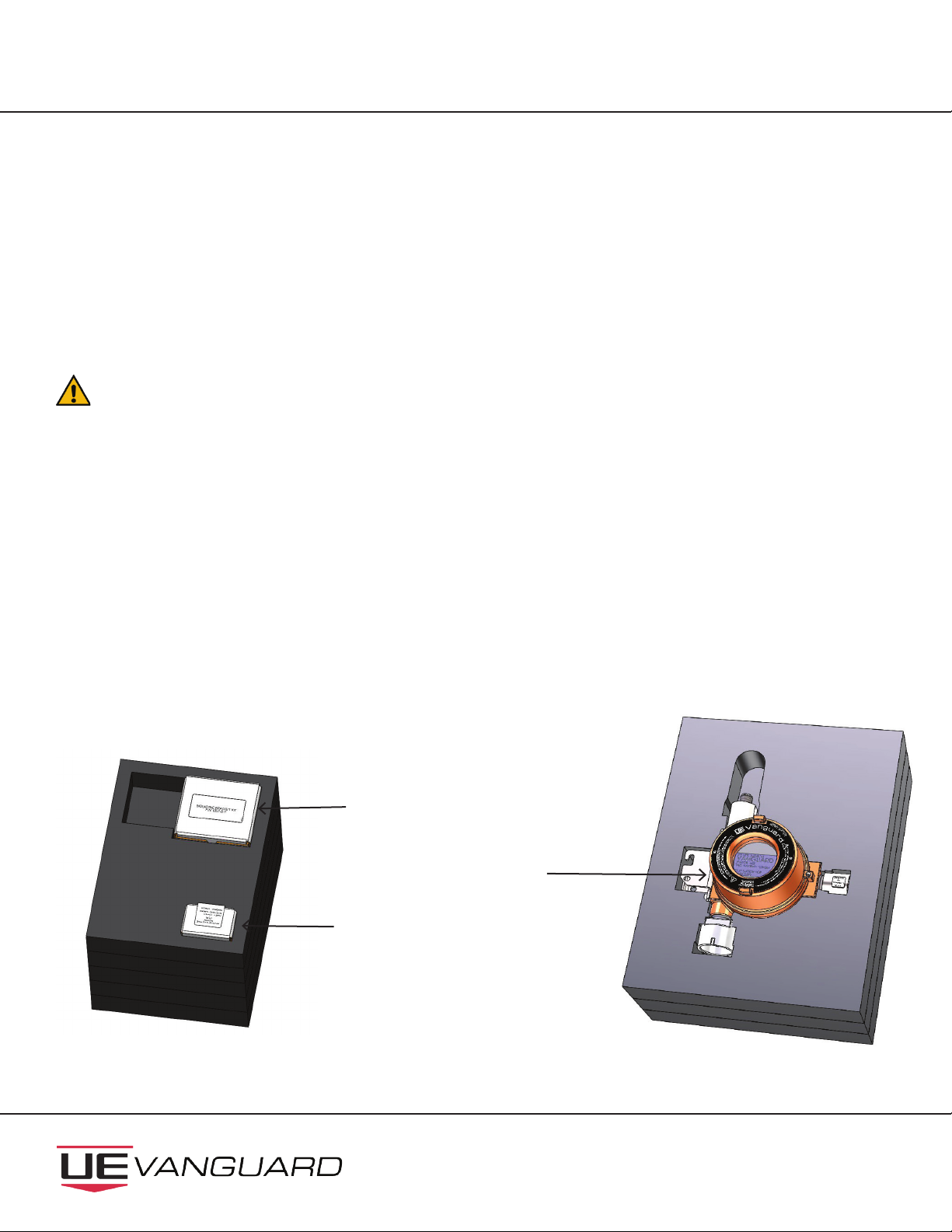
To ensure proper ingress protection, the front and rear covers must be installed, and fully bot-
tomed out against the base enclosure (i.e., metal-to-metal contact). It is recommended to use a
wrench or any tool across the cover lugs to tighten the covers down.
Exposure to toxic gas may result in loss of consciousness or death. See Annex 1 for toxic
gas sensor details.
Combustible gas accumulation in closed areas may cause explosion, and result in loss of
consciousness or death. See Annex 1 for combustible gas sensor details.
Avoid dropping the device as loosening of the threaded ame-proof joints or permanent damage
may occur.
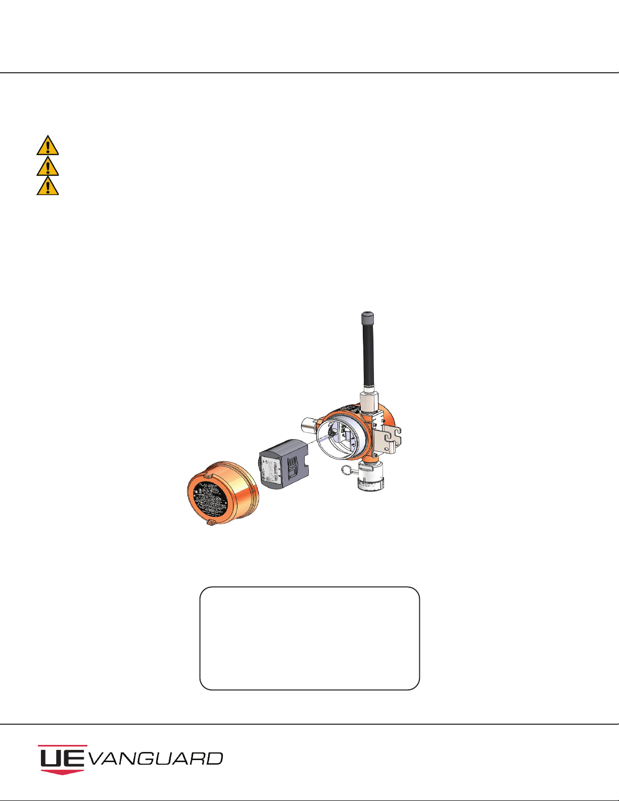
New sensors must be calibrated after installation (see Section 3.2).
When not in use, the device should be stored in a clean, dry area and within the temperature
range listed within the device’s environmental specications.
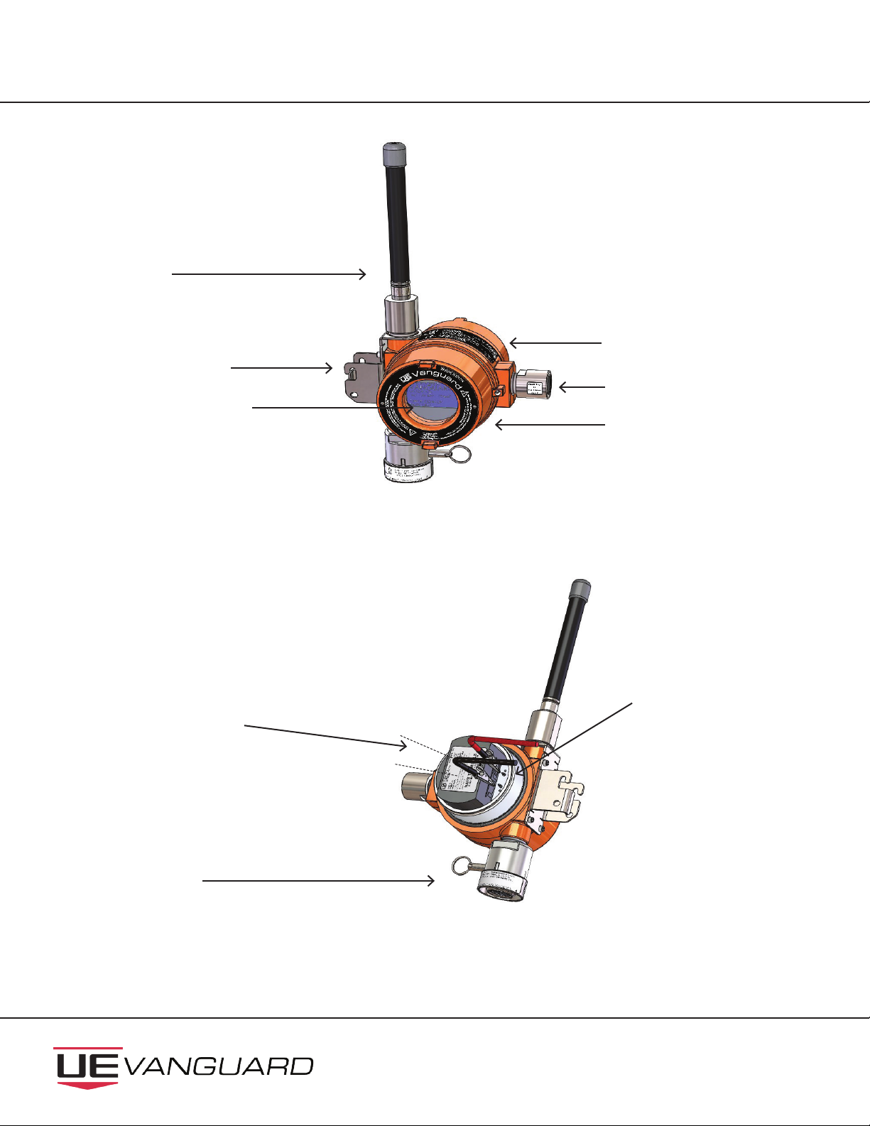
1.1 Device Overview
The device is an explosion-proof and intrinsically safe, WirelessHART point gas detector used for the de-
tection and monitoring of harmful gases in air, in order to help maintain a safe environment. A eld-inter-
changeable gas sensor module (see Figure 1) provides detection of toxic or combustible gas. Gas measure-
ment readings are communicated along with network and battery status (see Figure 2) via a local, digital
display, and WirelessHART 7.2 communication protocol. The device seamlessly integrates with existing
supervisory control and data acquisition (SCADA) or asset management (AMS) systems.
Sensor specications are available online or in Annex 1 which can be downloaded from www.ueonline.com/
vanguard.

WirelessHART Toxic & Combustible Gas Detector IM_TCD60-01
www.ueonline.com/vanguard
2
Heavy duty, explosion-
proof antenna
Explosion-proof (Ex d)
compartment
Integral FLEXmount™
bracket
Graphic display shows gas
concentration, network
Intrinsically Safe battery
compartment. Battery is
hot swappable in HazLoc
areas
Large shrouded button allows
access to calibration mode and
bump testing
Battery allows one
handed, quick-change
replacement
FLEXsense™ sensor is intrinsically
safe and hot swappable in HazLoc
areas. Toxic or combustible gas
sensors automatically congure
when interchanged.
WiredHART interface
for conguration and
testing
Figure 1
Figure 2

WirelessHART Toxic & Combustible Gas Detector
IM_TCD60-01
www.ueonline.com/vanguard
3
1.2 Device Packaging
The device may be shipped in one of the following two congurations. Please ensure that all items have
been received before proceeding with installation and operation.
1. Base unit and mounting bracket kit with toxic or combustible FLEXsense™ sensor (Figure 3 and Figure 4).
2. Base unit and mounting bracket kit only (Figure 3 without sensor and Figure 4).
Device is shipped without the sensor or battery installed. Both must be installed prior to use. See
Section 2.0 Installation for further information.
1.2.1 Sensors
One FLEXsense™ sensor is shipped (but uninstalled) with the base unit (if ordered in that conguration). Ad-
ditional, spare FLEXsense™ sensors may be ordered and will ship separately.
1.2.2 Battery
The battery pack is shipped separately from the base unit as it contains lithium which is regulated in trans-
portation by the U.S. Department of Transportation, the International Air Transport Association, International
Civil Aviation Organization, and European Ground Transportation of Dangerous Goods.
FLEXsense™Sensor
Base Unit
Mounting
Bracket Kit
Figure 3 Figure 4
Top foam for packaging Bottom foam for packaging

WirelessHART Toxic & Combustible Gas Detector IM_TCD60-01
www.ueonline.com/vanguard
4
This device is suitable for Class I, Divisions 1 & 2, Groups A,B,C,D; or non-hazardous locations only.
-40°C (-40°F) ≤ Tamb. ≤ 65°C (149°F)*. Type 4X and IP66**.
This product is ATEX and IECEx certied for equipment category 2. Suitable for appropriate use in gas
zone 1.
The only eld replaceable parts are the battery pack and FLEXsense™ sensor. Any substitution of
components other than the battery and gas sensor module will invalidate third-party issued ap-
provals and certications, and may impair suitability for Class I, Division 1 location.
5003390
Global Certication
IECEx ETL 21.0065X
Ex db ia [ia] IIC T4 Gb
-40°C < Tamb < +65°C*
EU Certication
II 2 (2) G Ex db ia [ia] IIC T4 Gb
ITS-I21ATEX31360X
-40°C < Tamb < +65°C*
North American Certication
Class I Div. 1, Groups A,B,C,D, T4
USA: Class I, Zone 1, AEx db ia [ia] IIC T4 Gb
Enclosure Type 4X, IP66**
Canada: Class I, Zone 1, Ex db ia [ia] IIC T4 Gb
ETL21CA104546645X
-40°C < Tamb < +65°C*
*Ambient operating temperature range may vary with sensor
type. See Technical Brochure for sensor specications.
**Enclosure Type 4X and IP66 rating excludes sensor.
UE declarations and third-party issued agency certications are available for download at: www.ueonline.
com/prod_approval.
1.3 Device Approvals
5003390

WirelessHART Toxic & Combustible Gas Detector
IM_TCD60-01
www.ueonline.com/vanguard
5
The device has been certied in accordance with the applicable requirements of the following standards:
Each certicate lists the standard, along with standard revision or date, which this Vanguard product
meets. See DEMKO 11 ATEX 1105261X for EN Standards,
See IECEx UL 14.0075X for IECEx Standards. The North America, ATEX (Europe), and IEC (International)
certicates are available for download on the UE website: www.ueonline. com/prod_approval

WirelessHART Toxic & Combustible Gas Detector IM_TCD60-01
www.ueonline.com/vanguard
6
2.0 INSTALLATION
2.1 Battery Installation
Only battery packs provided by United Electric Controls are compatible with this device.
Battery should be removed and stored when the device is not in use.
Batteries are not rechargeable.
The battery pack contains two Lithium-Thionyl Chloride D size cells, with a nominal output voltage of 7.2V.
1. Unscrew the solid, back cover from the intrinsically safe battery compartment and set aside.
2. Remove the battery pack from its packaging.
3. Align battery pack so connection on the pack lines up with connection in the enclosure.
4. Slide the battery pack into the enclosure until it latches in place as shown in Figure 5.
5. The device is now powered and will show the word STARTING along with the hardware and software ver-
sions on the front panel display while initial boot-up completes (see Figure 6).
STARTING
HW VER : X.XX
SW VER : X.XX Figure 6
Figure 5

WirelessHART Toxic & Combustible Gas Detector
IM_TCD60-01
www.ueonline.com/vanguard
7
6. When hardware and software boot-up is complete, the device will prompt user to activate the installed sen-
sor (see Figure 7)
Refer to section 2.2 for sensor activation sequence.
7. Once activation is done, the front panel display will display the device name, HART long tag, and the software
version, along with an instruction to push button to show gas concentration (see Figure 8).
8. The device is now ready to be congured for deployment into a WirelessHart network. It is recommended to
connect the device to the network immediately after battery installation to maximize battery life. Refer to
section 2.8 for network conguration.
9. Once device conguration is complete, secure cover onto enclosure by tightening until all threads have been
fully engaged to ensure proper ingress protection.*
*NOTE: To ensure proper ingress protection, the rear cover must be installed, and fully bottomed out against the base
enclosure (i.e., metal-to-metal contact). It is recommended to use a wrench or any tool across the cover lugs to tighten the
covers down.
VANGUARD
SENSOR NOT
ACTIVATED : CH4
PUSH BUTTON TO
ACTIVATE SENSOR
Figure 7
SW VER: X.XX
VANGUARD
SENSOR: CH4
TAG : KANBAN XXXXXX
PUSH BUTTON TO
SHOW CONCENTRATION
Figure 8

WirelessHART Toxic & Combustible Gas Detector IM_TCD60-01
www.ueonline.com/vanguard
8
2.2 Sensor Installation
Only FLEXsense™ sensors provided by United Electric Controls are compatible with this device.
Do not attempt to disassemble the sensor as this could damage the sensor and void hazardous location
approvals, and manufacturer warranty.
Sensors must be activated after installation.
Ensure base unit has a sensor installed at all times when mounted outdoors to prevent damage to connectors
due to ambient moisture.
Sensors are packaged fully assembled and require simple installation into the base unit. Toxic sensors are comprised of
an electrochemical sensor packaged into a stainless steel housing. Combustible sensors are comprised of an infrared
sensor packaged into a stainless steel housing. These are consumable, eld replaceable parts (see Section 4.1, Sensor
Replacement).
1. Remove FLEXsense™ sensor from packaging.
2. Retract the sensor locking pin and twist 90 degrees to lock in retracted position.
3. Align the locating pins (see Figure 9) on the FLEXsense™ sensor to the keyed positions on the sensor housing (see
Figure 10).
4. Insert the sensor. A click will be felt and heard, ensuring the sensor has been inserted correctly.
5. Twist the sensor locking pin 90 degrees and release to engage the sensor locking pin.
6. Push button to activate sensor.
For Combustible Sensor Only
7. Once the button is pushed, the base transmitter initializes the sensor activation process. During this activation, the
screen in Figure 11 will be displayed. This activation may take up to 2 minutes.
Figure 9
Locating pins
Figure 11
ACTIVATING
PLEASE
WAIT
Figure 10

WirelessHART Toxic & Combustible Gas Detector
IM_TCD60-01
www.ueonline.com/vanguard
9
2.3 Sensor Placement Considerations
Exposure to toxic gas may result in loss of consciousness or death. See Annex 1 for toxic gas
sensor details.
Combustible gas accumulation in closed areas may cause explosion, and result in loss of con-
sciousness or death. See Annex 1 for combustible gas sensor details.
This device must be mounted vertically with the sensor pointing downward.
This device is suitable for Class I, Divisions 1 & 2, Groups A,B,C,D; or non-hazardous locations only. -40°C
(-40°F) ≤ Tamb. ≤ 65 °C (149°F)*. Enclosure Type 4X and IP66**
This device is ATEX and IECEx certied for equipment category 2. Suitable for appropriate use in
gas zone 1.
*Ambient operating temperature range may vary with sensor type. See Technical Brochure for sensor specica-
tions.
**Enclosure Type 4X and IP66 rating excludes sensor.
Individual applications need to be assessed for correct sensor placement. The target gas needs to be determined
along with the gas density, and potential coverage area.
8. The device will prompt the user to zero the oset. As shown in Figure 12.
A. To zero the oset, press and hold the calibration button until seeing the display screen in Figure 13. This
takes about 10 seconds.
B. To ignore the oset, press and release the calibration button to skip the zeroing process to step 9.
For All Sensors
9. Once the sensor initialization process is complete, a“Sensor Active Calibrate New Sensors” message will show (see
Figure 14) before automatically returning to home screen (Figure 8).
10. The sensor is self-conguring with the device and once booted up (see Section 2.8 Network Conguration) will
display the proper gas concentration.
NOTE: To zero the combustible sensor at any time, press and hold the calibration button for 10 seconds. Refer to
section 2.2, step 8, to continue sequence.
Figure 13
ZEROING DONE
SENSOR ACTIVE
CALIBRATE NEW SENSOR
SENSOR
ACTIVE
CALIBRATE
NEW SENSORS
Figure 14
Figure 12
CH4 XX
PRESS AND HOLD BUTTON
TO ZERO SENSOR
OR PUSH TO SKIP
%LEL

WirelessHART Toxic & Combustible Gas Detector IM_TCD60-01
www.ueonline.com/vanguard
10
Chemical Abstracts Service (CAS), a division of the American Chemical Society, is the world’s authority for chemical
information. Please consult the database at www.cas.org for chemical properties of gas.
Other factors to consider include but are not limited to:
• Location – takes into account gas leak source, pressure of release, temperature, and distance to sensor.
• Air ow – prevailing winds, velocity, fans, exhaust ducts that could aect detection.
• Environmental conditions – other than air ow; such as exposure to water, snow, and dirt. Also temperature – hot
and cold – and how that may aect the gas release.
• Maintenance Accessibility – provide safe access for calibration and maintenance.
2.4 Sensor Cross Sensitivity
Depending on the type of sensor installed, the device has the ability to detect either Toxic or Combustible gas. The
tables and graph located in Annex 1 demonstrate the typical cross sensitivities of each sensor to other gases that may
be present while monitoring.
For gases that are heavier than air, sensor installation is recommended near the ground and below the
potential leak source.
For gases that are lighter than air, sensor installation is recommended near the ceiling (in an enclosed
space) and above the potential leak source.

WirelessHART Toxic & Combustible Gas Detector
IM_TCD60-01
www.ueonline.com/vanguard
11
2.5 Classied Area Installation
This device is suitable for Class I, Divisions 1 & 2, Groups A,B,C,D; or non-hazardous locations only. -40°C
(-40°F) ≤ Tamb. ≤ 65°C (149°F)*. Enclosure Type 4X and IP66**.
This device is ATEX and IECEx certied for equipment category 2. Suitable for appropriate use in
gas zone 1.
Install device only into areas matching approvals on device labeling.
Do not remove the front (painted aluminum and glass) cover in hazardous area.
Install the device where shock, vibration and temperature uctuations are minimal. Do not mount in ambient
temperatures that exceed the limits on the device labeling.
This device is for monitoring and communicating gas concentration levels for data collection or record keeping
and does not provide any alarm signals.
To prevent seizure of enclosure cover, do not remove lubricant. Threads should also be free of dirt, etc.
*Ambient operating temperature range may vary with sensor type. See Technical Brochure for sensor specications.
**Enclosure Type 4X and IP66 rating excludes sensor.
2.6 Field Mounting
This device must be mounted vertically with the sensor pointing downward.
Install device where shock, vibration and temperature uctuations are minimal. Do not mount in ambient
temperatures that exceed the limits on the device labeling.
The mounting bracket attachment on this device is factory-installed and must not be removed as it may
cause permanent damage to the antenna, the sensor assembly, and loosening of the threaded ame-proof
joints. Removal will void hazardous location approvals, and manufacturer warranty.
This device may be mounted in any of the following congurations using any of the three Vanguard FLEXmount™ op-
tions: Standard mount, Magnet mount, or Universal mount.

WirelessHART Toxic & Combustible Gas Detector IM_TCD60-01
www.ueonline.com/vanguard
12
2.6.1 Standard Mount - Vertical
1. Remove hardware from packaging (see Figure 15).
2. Place one pipe mount adaptor [1] onto desired location horizontally on pipe and slide U-bolt [2] through
holes.
3. Slide mounting bracket plate [3] onto U-bolt [2] and secure with (2x) hex nuts [4]. Do not tighten.
4. Repeat step 2 with second pipe mount adaptor [1] also sliding U-bolt [2] through mounting bracket
plate [3] and securing with (2x) hex nuts [4].
5. Once position is set, tighten (4x) hex nuts using 1/2” wrench.
6. Mount device by hooking onto top pin of mounting bracket plate (see Figure 16).
7. Push attached pin [5] through bottom holes to secure device to the bracket (see Figure 17).
Figure 15 Figure 16
Figure 17
[1]
[2] [3]
[4] [5]

WirelessHART Toxic & Combustible Gas Detector
IM_TCD60-01
www.ueonline.com/vanguard
13
2.6.2 Standard Mount - Horizontal
1. Remove hardware from packaging (see Figure 15).
2. Place one pipe mount adaptor [1] onto desired location vertically on pipe and slide U-bolt [2] through holes.
3. Slide mounting bracket plate [3] onto U-bolt [2] and secure with (2x) hex nuts [4]. Do not tighten.
4. Repeat step 2 with second pipe mount adaptor [1] also sliding U-bolt [2] through mounting bracket plate
[3] and securing with (2x) hex nuts [4].
5. Once position is set, tighten (4x) hex nuts using 1/2” wrench.
6. Mount device by hooking onto top pin of mounting bracket plate (see Figure 18).
7. Push attached pin [5] through bottom holes to secure device to the bracket (see Figure 19).
Figure 18 Figure 19
[1]
[2] [3]
[4]
[5]

WirelessHART Toxic & Combustible Gas Detector IM_TCD60-01
www.ueonline.com/vanguard
14
2.6.3 Standard Mount - Wall
Wall mounting could aect the signal strength of the device
1. Remove hardware from packaging (see Figure 20).
2. Hold mounting bracket plate [3] against wall/at surface and screw tightly into place using (4x) mount-
ing holes (0.40”dia.).
Note: Mounting screws [6] not UE provided.
3. Mount device by hooking onto top pin of mounting bracket plate (see Figure 21).
4. Push attached pin [5] through bottom holes to secure device to the bracket (see Figure 22).
Figure 20 Figure 21 Figure 22
[5]
[6]
[3]

WirelessHART Toxic & Combustible Gas Detector
IM_TCD60-01
www.ueonline.com/vanguard
15
2.6.4 Magnetic Mount
Caution: magnets may cause pinch points.
Magnet contact force is dependent on surface condition and atness. Mount to at, dry, clean surfaces that are
not subject to extreme environmental conditions.
This solution should not be used for overhead mounting.
1. Remove hardware from packaging (see Figure 23).
2. Attach device to mounting bracket by hooking onto top pin of mounting bracket plate (see Figure 24).
3. Push attached pin [5] through bottom holes to secure device to the bracket (see Figure 24).
4. Align magnet mount [7] to mounting location.
5. Place onto location gently or using a top-to-bottom“peeling” motion (Figure 25).
6. Use the same top-to-bottom peeling motion to remove the mount from the wall.
Figure 23 Figure 24
Figure 25
[5]
[7]

WirelessHART Toxic & Combustible Gas Detector IM_TCD60-01
www.ueonline.com/vanguard
16
2.6.5 Universal Mount
1. Remove hardware from packaging (see Figure 26).
2. Thread clamp [8] through the holes on the mounting bracket plate [3] (see Figure 26, 27).
3. Wrap the clamp [8] around the mounting structure and insert the end under the worm drive screw
[9] (see Figure 28).
4. Pull the end through until it is hand tight around the mounting structure and ip down the worm
drive screw [9].
5. Use a socket or screwdriver to tighten the clamp. This clamp should lock into place and be tool-tight.
6. Mount device by hooking onto top pin of mounting bracket plate (see Figure 28).
7. Push attached pin [5] through bottom holes to secure device to the bracket (see Figure 29).
2.6.6 Device removal from mounting bracket plate
Removing the device from the mounting bracket plate for maintenance or calibration is simple.
1. Pull attached pin [5] through bottom holes using the pull ring.
Figure 26 Figure 27
Figure 28
Figure 29
[9]
[5]
[3]
[8]

WirelessHART Toxic & Combustible Gas Detector
IM_TCD60-01
www.ueonline.com/vanguard
17
2.7 Antenna Placement Considerations
This device complies with Part 15 of the FCC rules: may not cause harmful interference; must accept any
interference, including that which may cause undesired operation of the device.
To comply with IC RF exposure compliance requirements, the antenna used for this device must be
installed to provide a separation distance of at least 20cm from all persons.
FCC ID SJC-ETERNA2 contains IC 5853(A)-ETERNA2 CE0976
Wall mounting could aect the signal strength of the device.
The antenna supplied with the device is an omnidirectional antenna, permanently axed to the product.
In order to facilitate communication with other WirelessHART devices as part of a wireless mesh network, it
is recommended that the device be mounted with a minimum of obstructions and noise interference. The
maximum range of communication between the device and other devices
(instrumentation, repeaters, gateways) is 750 feet (229 meters).
2.8 Network Conguration
A Network ID and Join Key are required to communicate over the wireless network.
It is recommended that network conguration be performed right after battery installation to maximize bat-
tery life. The device must be congured to communicate over the wireless network. A Network ID and Join
Key are required, and must match the Network ID and Join Key of the wireless gateway and other wireless
devices in the network.
This device sends critical gas concentration information reliably and securely via WirelessHART
communication protocol, version 7.2. Conguration can be completed using the UE Vanguard
Congurator Unit, any HART handheld communicator, or directly into the control system using a HART
modem. HART terminals are located inside the intrinsically safe battery compartment and are clearly marked
(see Figure 24).
Conguring the gas detection device in the hazardous area requires a suitable, approved intrinsically safe device
(such as a handheld communicator, etc.). The entity parameters of the device being connected must be compat-
ible with those of the gas detection device.
Before connecting any device in the hazardous location, the following entity parameters must be veried:
Uo< Uiprog Lo> Liprog
Io< Iiprog Ui> Uoprog
Po< Piprog Ii> Ioprog
Co> Ciprog
Gas Detector Intrinsic Safety Entity Parameters:
Uo= 4.935V; Io= 0.179A; Po= 0.22W; Co= 25uF; Lo= 0.25mH
Ui= 3.8V; Ii= 64uA; Ci = Negligible; Li = Negligible
Table of contents
Other United Electric Controls Gas Detector manuals
Popular Gas Detector manuals by other brands

GASTRON
GASTRON GTD-1000Tx instruction manual

Dräger
Dräger PointGard 2000 Series Instructions for use

Dräger
Dräger PIR 7000 Instructions for use

New Cosmos Electric
New Cosmos Electric PS-7-M Communication Specifications Guide

Atex
Atex DGTt2-ex installation manual

New Cosmos Electric
New Cosmos Electric PS-7-M instruction manual

MSA
MSA Altair Pro quick start guide

Bühler technologies
Bühler technologies GAS 222.20 AMEX Brief instructions

Riken Keiki
Riken Keiki TP-70DGII operating manual

Crowcon
Crowcon AGP 45 operating instructions

CGS
CGS Merlin CO2 TFT Installation operation & maintenance

Critical Environment Technologies
Critical Environment Technologies LPT-M Operation manual