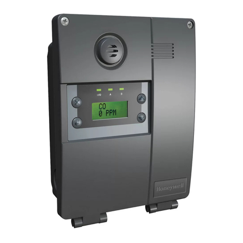
NEXTTEQ NXM User manual

INSTRUCTION MANUAL
Multi Gas Detector
®
Exclusive Nextteq®International Product
Multi Gas Detector

3
TABLE OF CONTENTS
1 PRODUCT INTRODUCTION.............................................. 4
1.1 KEY FEATURES ..................................................... 4
1.2 PROGRAMMABLE OPTIONS ...................................... 4
2 WARNINGS ................................................................ 5
2.1 CAUTION............................................................. 6
3 PRODUCT OVERVIEW.................................................... 6
3.1 DISPLAY SYMBOLS ................................................ 7
4 CHARGING AND ACTIVATING ........................................... 7
4.1 CHARGING........................................................... 7
4.2 POWER ON .......................................................... 7
4.3 POWER OFF ......................................................... 8
5 DEVICE OPERATIONS .................................................... 8
5.1 OPERATIONAL MODES ............................................ 8
5.2 DISPLAY MODES ................................................... 9
5.2.1 MEASURING MODE ........................................ 9
5.2.2 SAFE ZONE MODE.......................................... 9
5.3 DISPLAY SCREENS................................................10
5.4 DISPLAY DETAILS .................................................10
5.5 ALARMS AND NOTIFICATIONS ..................................13
5.6 DETECTED CONCENTRATION VALUES..........................15
5.7 ALARM VALUES ...................................................15
5.7.1 DEFAULT ALARM SETTINGS.............................16
6 SELF-TEST................................................................17
7 BUMP TEST...............................................................18
7.1 BUMP TEST REMINDER ..........................................18
7.1.1 CHECK BUMP TEST INTERVAL DATE AND LATEST
BUMP TEST DATE .........................................18
7.2 PERFORM A BUMP TEST.........................................19
8 CALIBRATION ............................................................21
8.1 CHECK SPAN CALIBRATION INTERVAL DATE AND LATEST ....
SPAN CALIBRATON DATE ........................................21
8.2 DEFAULT GAS CONCENTRATIONS FOR CALIBRATION.......21
8.3 ZERO (FRESH AIR) CALIBRATION...............................22
8.4 SPAN (STANDARD) CALIBRATION ..............................24
8.5 EXITING THE CALIBRATION MENU..............................26
9 LOGGING..................................................................26
10 MAINTENANCE AND DISPOSAL .......................................27
10.1 MAINTENANCE.....................................................27
10.2 DISPOSAL ..........................................................27
11 SPECIFICATIONS ........................................................28
12 WARRANTY...............................................................30
12.1 LIMITED WARRANTY .............................................30
12.2 WARRANTY DISCLAIMER ........................................31

4 5
Nextteq International LLC Toll Free: 877-312-2333 www.nextteq.com [email protected]Designed, built and supported by industry professionals for industry professionals.
1 PRODUCT INTRODUCTION
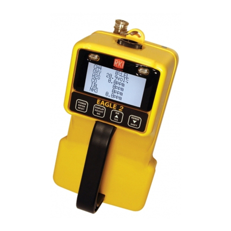
The NXM Multi Gas series is a diffusion gas monitor that
simultaneously detects up to four gases, including hydrogen sulfide
(H2S), carbon monoxide (CO), oxygen (O2) and combustibles (LEL).
The unit alarms in three ways: visual, vibration, and audible when the
risk occurs. A dual sensor detects both CO and H2S.
The NXM displays real-time gas concentrations with configurable
settings for high and low alarm points for each sensor plus STEL and
TWA alarm points for toxic gases. The unit will operate continuously
for up to 60 days on a battery charge. Sensors for combustible gases
are offered in either Catalytic Bead or Infrared.
1.1 Key Features
• Small and lightweight
• Stores up to 30 Events (Alarms/Bump Tests/Calibration/Data)
• Simultaneously monitors and detects 4 different gases
• Easy-to-read LCD display
• Single button operation
• Rugged housing
• IP67 dust tight and water resistant
• IR sensor is immune to poisoning
• IR sensor detects LEL gases in inert (O2 deficient)
environments
• 60-day use with one 4–6-hour charge
• Configuration via NXI exclusive IR link
• Easy check and calibration via NXI Docking Station
• Combustible (LEL) available with either IR Sensor (P/N
NX90221) or Catalytic Bead Sensor (P/N NX90222)
1.2 Programmable options
The options below are configured with the IR Link software.
• Stealth Mode
• Go/No Go display
• Bump Test due
• Calibration due
• Calibration gas concentrations
• Alarm levels
• STEL and TWA levels
• Firmware updates
2 Warnings
• Any unauthorized attempt to repair or modify the product,
or any other cause of damage beyond the range of the intended use
including damage by fire, lightning, or other hazard, voids liability of
the manufacturer.
• Do not use the device if it appears to be damaged.
• Remove any debris from the surface of the sensor, LED, or buzzer
hole before use.
• Test the performance of the gas sensor beyond the alarm level
regularly.
• Test the device on a regular basis to ensure the LED, alarms, and
vibration actions function properly.
• Use the device under the conditions instructed, including the
temperature, humidity, and pressure range. An environment
outside the user instructions may cause malfunction or failure.
• The sensors inside the device may indicate the gas concentration
differently according to the environment such as temperature,
pressure, and humidity. Calibrate the detector under the same or a
similar environment to the specification.
• Extreme changes in temperature may cause drastic changes of
the gas concentration (e.g. using the detector where there is a huge
gap between the inside and outside temperature). Use the device
when the concentration becomes stable.
• Severe pressure or impact may cause drastic changes of the gas
concentration. Therefore, please use the device when the
concentration is stable. Severe pressure or impact may also cause
malfunction in the sensor or the device.
• The alarms are set according to international standards and must be
changed by an authorized expert.
• Charging or replacing the battery should be done in a safe area
where there is no risk of explosion or fire. Changing the sensor
or battery with improper replacements, which are not authorized
by the manufacturer, may invalidate the warranty.
• IR communication should be done in a safe area where there is no
risk of explosion or fire.
• Do not use expired gas cylinders.
• Use certified gas cylinders only.
• Do not use a gas detector which has failed or cannot pass a bump
or calibration test.

6 7
Nextteq International LLC Toll Free: 877-312-2333 www.nextteq.com [email protected]Designed, built and supported by industry professionals for industry professionals.
2.1 Caution
• Read the manual before first use and follow all instructions.
• The device is not a measurement device, but a gas detector.
• Please stop using and consult the manufacturer if the
calibration fails continuously.
• Test the device every 30 days under the atmospheric
environment of clean air without gases.
• Clean the exterior of the device with a soft cloth. Do not use
chemical detergents.
3. Product Overview IR Port
Display
Multifunction Key
LEL Sensor
O2Sensor
Alarm
LEDs
Alarm
LEDs
Alarm
Buzzer
Dual
CO & H2S
Sensor
HIGH
High Alarm Fresh Air Calibration
LOW
Low Alarm Device Stablilization
& Calibration Successful
Alarm Condition Standard Gas
Calibration
STEL
Short Term
Exposure Limit
Alarm
Remaining Battery
TWA
Time Weighted
Average Alarm
3.1 Display symbols
4 CHARGING AND ACTIVATING
4.1 Charging
The NXM Multi-Gas Monitor ships with a charging cable and a
selection of the more common wall plugs.
1) Choose the correct plug for the type of wall outlet available and
attach it to the power supply.
2) Insert the adapter to the charging slot on the bottom of the
unit.
3) Plug the other end into a standard outlet.
4.2 Power On
Press and hold down the MULTIFUNCTION KEY for 3 seconds until
the device switches on..
(The device will power on only when pressing the key for longer
than 3 seconds.)

8 9
Nextteq International LLC Toll Free: 877-312-2333 www.nextteq.com [email protected]Designed, built and supported by industry professionals for industry professionals.
5.2 Display Modes
5.2.1 Measuring Mode
Measuring Mode is the default display. Oxygen is displayed in
% by volume, combustible gases in %LEL, and H2S and
CO in PPM units. The values are displayed in
real time. If the levels exceed the threshold
for either LOW alarm or HIGH alarm or TWA/
STEL, the display icons of LOW, HIGH, TWA
or STEL blink regularly and the audible, LED,
and vibration alarms activate. Exit the area
immediately.
When the device enters a safe area and the concentrations
detected by the device decline, the alarm stops. A device in
a safe area after an alarm will continue to display the icon of
the alarm until the MULTIFUNCTION KEY is pressed.
5.2.2 Safe Zone Mode
Safe Zone Mode is used as a go/no-go monitor. If
concentrations exceed an alarm threshold, alarms will
activate as described in Measuring Mode and
Oxygen is displayed in % by volume,
combustible gases in %LEL, and
H2S and CO in PPM. If the alarms
activate, exit the area immediately.
When the device enters a safe area and the
concentrations detected by the device decline, the alarm
stops. A device in a safe area after an alarm will continue to
display the icon of the alarm until the MULTIFUNCTION
KEY is pressed.
During the power up sequence, the display will cycle through the
gas types, firmware version, display test and alarm test, followed
by a 10-second warm up. Once powered, the device will enter an
additional warmup stage to stabilize the sensors. When the warmup
process is complete, the device will enter measuring mode and is
ready to detect gases.
Caution A proper calibration is always required before using the
device at the work site. The user shall check whether the device
is properly sensing the levels of dangerous gases and ensure the
detecting section of the device is not blocked.
4.3 Power Off
Press and hold down the MULTIFUNCTION KEY until the device
switches off after a 3-second countdown.
(The device will power off only when pressing the key for longer
than 3 seconds.)
5 DEVICE OPERATIONS
5.1 Operational Modes
• Measuring Mode
The device displays real-time gas concentrations and the battery
power level.
• Safe Zone Mode
The device displays SAFE ZONE unless concentrations exceed an
alarm threshold.

10 11
Nextteq International LLC Toll Free: 877-312-2333 www.nextteq.com [email protected]Designed, built and supported by industry professionals for industry professionals.
5.3 Display Screens
Display screens are visible in the following order by pressing the
MULTIFUNCTION KEY
Measuring Mode
Default display.
Minimum Concentration
The lowest gas concentration that the O2 sensor has
detected since the measurements were last cleared.
Time Weighted Average
The acceptable average concentration level of each gas
over the last eight hours.
Short Term Exposure Limit
The acceptable average concentration level of each gas
over the last 15 minutes.
Clear Stored Values
Clear Low, High, TWA, STEL values. To clear, press and
hold the MULTIFUNCTION KEY for 3 seconds. The unit
beeps once then displays OK. Press the MULTIFUNCTION
KEY to continue through the display screens or wait 10
seconds to return to Measuring Mode.
Alarm Values
Displays the alarm values for each gas. Press and hold
the MULTIFUNCTION KEY for 3 seconds to enter the Alarm
Values menu, then step through LOW, HIGH, TWA, STEL
values by pressing the MULTIFUNCTION KEY.
Note: The screen will revert to measuring mode if the
MULTIFUNCTION key is not pressed within 10 seconds.
5.4 Display Details

12 13
Nextteq International LLC Toll Free: 877-312-2333 www.nextteq.com [email protected]Designed, built and supported by industry professionals for industry professionals.
5.5 Alarms and Notifications
Type Alarm
Condition
LCD Display Audio/Visual/
Physical Display
Action
Low
Alarm
LOW alarm
value
exceeded Icon & gas
concentration
levels
displayed
Press the
MULTIFUNCTION
KEY to silience
audio. LED and
vibration continue.
High
Alarm
HIGH
alarm value
exceeded Icon & gas
concentration
levels
displayed
Leave the area
immediately!
Alarms stop when
the device is in
a safe area and
concentrations are
normal
TWA
Alarm
TWA alarm
value
exceeded Icon & gas
concentration
levels
displayed
Alarms stop when
gas concentration
levels reach the
configured alarm off
value and device is
in a safe area.
STEL
Alarm
STEL
alarm value
exceeded Icon & gas
concentration
levels
displayed
Alarms stop when
gas concentration
levels reach the
configured alarm off
value and device is
in a safe area.
LEL Sensor Type and Firmware Version
Displays the LEL sensor type. N (Non-Dispersive Infrared)
or P (Pellistor/Catalytic Bead)
Displays the current firmware version.
Press and hold the MULTIFUNCTION KEY for 3 seconds to
initiate a self-test.
Short Term Exposure Limit
The acceptable average concentration level of each gas
over the last 15 minutes.
Date/Time
Displays date by default. Hold the MULTIFUNCTION KEY
for 3 seconds to toggle back and forth between Date and
Time.
Note: The date and time automatically sync with that of
the PC when linked with the NXI IR-LINK.
Short Term Exposure Limit
The acceptable average concentration level of each gas
over the last 15 minutes.

14 15
Nextteq International LLC Toll Free: 877-312-2333 www.nextteq.com [email protected]Designed, built and supported by industry professionals for industry professionals.
5.6 Detected Concentration Values
View as described under Display Details. To clear the values,
do the following. Press MULTIFUNCTION KEY for 3 seconds on
the CLR (Clear) mode on the LCD monitor. OK will appear on the
LCD monitor to notify the completion of the initialization.
5.7 Alarm Values
To view configured alarm values, do the following. Press the
MULTIFUNCTION KEY for 3 seconds in ALARM VAL mode. The
configured value for the LOW alarm is displayed. Press the
MULTIFUNCTION KEY once to cycle through and view each
alarm value.
Type Alarm
Condition
LCD Display Audio/Visual/
Physical Display
Action
Over
Range
Alarm
Gas
concentrations
exceed
maximum
sensor range
Press the
MULTIFUNCTION
KEY or reset the
device to clear.
See LEL sensor
types for more
info.
Bump
Test
Bump Test due
for gas sensor
indicated on
display
Clears after
successful Bump Test
Notifies the
user to perform
a bump test
at intervals
specified using
the IR-LINK.
Execute
Calibration
Calibration
due for
gas sensor
indicated on
display
Clears after
successful Calibration
Notifies the
user to perform
a calibration
test at intervals
specified using
the IR-LINK.
Calibration
Failed
Displays
sensor failing
calibration
Clears after
successful Calibration

16 17
Nextteq International LLC Toll Free: 877-312-2333 www.nextteq.com [email protected]Designed, built and supported by industry professionals for industry professionals.
6 SELF-TEST
Press the MULTIFUNCTION KEY to cycle
through the menus until sensor type and
firmware version are displayed. Press and
hold the MULTIFUNCTION KEY for 3 seconds.
The device will start the self-test to check the
Buzzer, LED, LCD, Vibration Motor, Memory,
and Temperature functions.
5.7.1 Default Alarm Settings
Setting Combustible
(Lower
Explosive
Limit)
O2 CO H2S
LOW Alarm 10% LEL 19.5% 35 ppm 5 ppm
HIGH Alarm 20% LEL 23.5% 200 ppm 10 ppm
TWA 25 ppm 1 ppm
STEL 200 ppm 5 ppm
Caution The values of different gases in the device are set based
on international standards. The alarm values for each gas can be
modified upon the approval and monitoring of an authorized expert.
The modification may be done through NXI IR-LINK under the
Options Menu.
Dates and Times
Press the MULTIFUNCTION KEY for 3
seconds while viewing the date to cycle to
the day and time. Press the MULTIFUNC-
TION KEY for 3 seconds to return to the
date display.
Note: The current time is automatically
synchronized with the PC when linked to
the NXI IR-LINK.

18 19
Nextteq International LLC Toll Free: 877-312-2333 www.nextteq.com [email protected]Designed, built and supported by industry professionals for industry professionals.
7.2 Perform a Bump Test
1) Check the Measuring Mode
display to ensure that the 02
sensor reads 20.9 and the other
gases read zero.
2) Clip the calibration cap to the
front of the unit as shown.
You should hear a click when
the cap is installed correctly.
Note: Be sure the word
“Calibration” is at the top of
the cap.
3) Check the regulator
connection to the gas
bottle and the hose
connections to the calibration
cap and the regulator to ensure
there are no leaks. Note: Do not
turn on the gas at this point.
4) Press the MULTIFUNCTION KEY
under CAL SPAN to enter BUMP
TEST mode.
5) Press the MULTIFUNCTION
KEY to advance to the Bump
Test screen. BUMP TEST
displays.
7 BUMP TEST
A bump test verifies the device is working correctly. A known
concentration of gas is applied to the sensors to confirm the
unit detects the gas and the alarms trigger.
Do not use the monitor until a successful Bump Test or Calibration is
performed. A Bump Test should be performed daily before use.
Perform the Bump Test in a clean environment.
7.1 Bump Test Reminder
The bump test reminder option is enabled using the NXI IR
Link and software or the NXI docking station. The reminder
can be set from n/a (off) to 365 days. Off is the default.
7.1.1 Check bump test interval date and latest bump test date
Cycle through the menus until BUM CAL DATE appears.
Press the MULTIFUNCTION KEY button for 3 seconds to view
the BUM DATE. Press the MULTIFUNCTION KEY button for 3
seconds to continue cycling through the screens. The interval
date set via IR-Link is displayed. Bump test interval date and
the latest bump test date will appear in the order above.

20 21
Nextteq International LLC Toll Free: 877-312-2333 www.nextteq.com [email protected]Designed, built and supported by industry professionals for industry professionals.
8 CALIBRATION
The calibration process adjusts the sensors’ responses by using a
known concentration of calibration gas. Sensors will become less
accurate for several reasons so a full calibration should be performed
on a regular basis to ensure accuracy. A full calibration consists of a
2-step process consisting of a Zero (fresh air) calibration and a Span
Calibration.
Calibration should be performed before the first use, one year after the
purchase and regularly every six months.
Zero Calibration adjusts the zero offset of the toxic gas and LEL
sensors to zero and sets the oxygen sensor to 20.9% Vol.
Span Calibration adjusts the toxic gas sensor response to account for
sensor drift. Always perform a Zero Calibration prior to a Span
Calibration.
8.1 Check span calibration interval date and latest span
calibraton date
Press the KEY button ( ) for three seconds under the Cal
Date when you set the interval date via IR-Link. The set value for
interval is displayed, calibration interval date and latest
calibration date will appear in the mentioned order.
8.2 Default Gas Concentrations for Calibration
The concentration for calibration may be modified on a PC
through NXI IR-LINK (Options Menu).
3 sec
6) Press and hold the MULTI-
FUNCTION KEY to start the
Bump Test. GAS NO and
a 45-second timer are displayed.
7) Turn on the gas regulator. GAS
IN is displayed and alternates
with real-time gas measure-
ments. The 45-second timer
counts down. Results appear
in approximately 20 seconds.
8) If the Bump Test is successful,
OK appears in all 4 sections of
the display.
9) If the Bump Test fails, the
sensor(s) that are suspect is/are
displayed. The display continues
to flash with the failure results
until a successful Bump Test or
Calibration is performed.
a. Check calibration gas concen-
trations, cylinder expiration
date, and device gas settings
then retest the unit.
b. If the unit fails on re-test,
perform a Zero Calibration
followed by a Span
Calibration.
The unit must be calibrated if it
fails a Bump Test.
Do not use the Multi-gas
Monitor until the discrepancies
are identified and addressed.
10) Turn off the gas regulator,
disconnect the hose and
calibration cap, and wait for the
gas to dissipate.

22 23
Nextteq International LLC Toll Free: 877-312-2333 www.nextteq.com [email protected]Designed, built and supported by industry professionals for industry professionals.
3) A 10-second countdown begins
and the device cycles through
detected gas level displays.
4) If the Zero Calibration is
successful, OK appears
in all 4 sections of the
display for approximately 5
seconds then returns to the
CAL ZERO display. Press the
MULTIFUNCTION KEY to the
CAL ESC to exit or wait
approximately 10 seconds for
the unit to return to the
Measuring Mode menu.
5) If the Zero Calibration fails, the
sensor(s) that is/are suspect
is/are displayed. The display
continues to flash with the
failure results until a
successful Calibration is
performed.
If the calibration continues to
fail, discontinue use and
contact Nextteq Technical
Support.
1) From the Measuring Mode menu,
press the MULTIFUNCTION KEY
to cycle through the menus to
the Calibration Menu.
2) Press and hold the
MULTIFUNCTION KEY for 3
seconds to access the
Calibration menus. CAL ZERO
will display. Press and hold the
MULTIFUNCTION KEY for 5
seconds to begin the calibration
process.
Gas Type Combustible Oxygen Carbon
Monoxide
Hydrogen
Sulfide
Concentration 50%LEL(CH4) 17 %Vol 100 ppm 25 ppm
Caution: The initial calibration is executed at the manufacturer before
device release. The calibration values are saved in the device which
means inaccurate calibration may impair the accuracy of the device
performance. Normally, the calibration should be done once a year
after the purchase and regularly every six months thereafter.
8.3 Zero (Fresh Air) Calibration
Calibration assumes that the oxygen concentration
is 20.9% vol, the combustible gas level is 0%LEL, and
the toxic gas level is 0ppm in normal fresh atmospheric
conditions; therefore, fresh air calibration must be conducted in
clear air without impact from other gases. Fresh air calibration in
airtight spaces is not recommended. Be sure to avoid operation
in work environments where people may inhale gases.

24 25
Nextteq International LLC Toll Free: 877-312-2333 www.nextteq.com [email protected]Designed, built and supported by industry professionals for industry professionals.
8.4 Span (Standard) Calibration
If not already completed, perform a Zero Calibration. When
performing a Span Calibration, use certified calibration gas at the
required concentration level. Do not use expired calibration gas.
Note: All alarms are muted for approximately one minute after a successful
Span Calibration.
1) Check the Measuring Mode
display to ensure that the 02
sensor reads 20.9 and the other
gases read zero.
2) Clip the calibration cap to the
front of the unit as shown. You
should hear a click when the cap
is installed correctly. Note: Be
sure the word “Calibration” is at
the top of the cap.
3) Check the regulator connection
to the gas bottle and the hose
connections to the calibration cap
and the regulator to ensure there
are no leaks. Note: Do not turn on
the gas at this point.
4) Cycle through the display screens
by pressing the MULTIFUNCTION
KEY to reach the Calibration
screen.
5) Press and hold the
MULTIFUNCTION KEY for 3
seconds to enter the Calibration
menu. CAL ZERO displays.
6) Press the MULTIFUNCTION KEY
to advance to the Span Calibration
screen. CAL SPAN displays.
7) Press and hold the
MULTIFUNCTION KEY for 5 seconds
to start the Span Calibration. Ninety-
second timer appears in the lower
right corner while the display cycles
through detected concentrations of
each gas.
8) Turn on the gas regulator and
wait for the calibration timer to
reach zero.
9) If the Span Calibration is successful,
OK appears in all 4 sections of the
display.
10) If the Span Calibration fails, the
sensor(s) that is/are suspect is/are
displayed. The display continues to
flash with the failure results until a
successful Calibration is performed.
Clear the stored values, perform
a Zero Calibration and attempt
another Span Calibration.
If the unit continues to fail, contact
Nextteq Technical Support.
11) Turn off the gas regulator,
disconnect the hose and calibration
cap, and wait for the gas to
dissipate.
1
7
2
8
9
4
10
5
6

26 27
Nextteq International LLC Toll Free: 877-312-2333 www.nextteq.com [email protected]Designed, built and supported by industry professionals for industry professionals.
Log Categories Log Details Retention
EVENT Log (High, Low,
TWA, STEL) Alarm
Occurrence time,
Duration, Alarm Type,
Gas Concentration, Serial
Number
30
BUMP TEST Log Test date, Pass/non-
pass, Calibration Gas
Concentration, Detected
Concentration
30
CALIBRATION Log Date of the Calibration,
Type, Calibration Gas
Concentration, Detected
Concentration
2 months or more
DATA Log Time, Date of executing
IR-LINK, Concentration,
Alarm Types, Options
Records status every
second
2 months or more
10 MAINTENANCE AND DISPOSAL
10.1Maintenance
CAUTION: Do not clean the instrument in a hazardous environment.
Static charge build up may result in an explosion.
Clean the display and case as needed with a soft cloth. Do not use
detergents or chemicals. If necessary, dampen the cloth with water
only.
Install the Calibration Cap before cleaning the monitor case to keep
contaminants and moisture away from the sensors.
10.2 Disposal
Dispose of the device in accordance with local electronics
recycling or waste disposal regulations.
8.5 Exiting the Calibration Menu
To exit the Calibration Menu, do the following:
1) Press the MULTIFUNCTION KEY until CAL ESC is displayed.
2) Press and hold the MULTIFUNCTION KEY for approximately 5
seconds until the display returns to the Calibration screen.
3) Press the MULTIFUNCTION KEY again and the unit will return
to the Measuring Mode screen.
Note: If the MULTIFUNCTION KEY is not pressed within 20 seconds,
the display reverts to the Measuring Mode screen.
8.6 Docking Station
The NXI Docking Station can also be used to easily perform
calibration, bump test, and event management on multiple devices
at a time.
9 LOGGING
Event logs and data are stored in internal memory. Refer to the table
below for retention times. When the capacity is exceeded, the oldest
logs are overwritten.
Event logs can be downloaded using a PC through the NXI IR-LINK or
the NXI Docking Station.
Data log records the operation status every second. Normal data logs
do not last more than 2 months.

28 29
Nextteq International LLC Toll Free: 877-312-2333 www.nextteq.com [email protected]Designed, built and supported by industry professionals for industry professionals.
Battery Manufacturer: SAMSUNG SDI
Product Name: ICP103450S
Type: Lithium-Ion Charger
Nominal Voltage: 3.7V
Nominal Capacity: 2000mAh
Max Charging Voltage: 6.3V
Battery
Charge
Duration
NXM-P: 24 Hours
NXM-IR: 60 Days
Case Rubber-based over-molded case
Size (W x D x H) 2.36 x 1.57 x 4.64in
Weight 8.46 oz
Options and
Accessories
NX1000 (Sampling pump)
NXI IR-LINK
NXI Docking-Station
Certification NX1000 (Sampling pump)
NXI IR-LINK
NXI Docking-Station
Compatible options IR-LINK, Docking Station, Sampling Pump.
Compatible Nextteq®
options
Nextteq IR-Link
Docking Station
SP-pump 101
11 SPECIFICATIONS
Model NXM
Gas Combustible O2 CO H2S
Detecting Method Diffusion / Sampling (with optional Sampling Pump)
Measuring
Mechanism
Catalytic
(NXM-P)
NDIR (NXM-IR)
Electrochemical Electrochemical Electrochemical
Range 0~100 %LEL 0~30 %vol 0~500 ppm 0~100 ppm
Sensor life > 5 years < 3 years > 5 years > 5 years
Response
Time
< 15sec/90%scale
< 15sec/90%scale
< 30sec/90%scale
< 30sec/90%scale
Accuracy ± 3%/ Full Scale
Resolution 1%LEL 0.1 %vol 1 ppm 0.1 ppm
Operation MULTIFUNCTION KEY
Display Digital LCD display, LCD Backlight, Indicator LED
Alarm Visual: LCD alarm display, LCD Backlight, Indicator LED
Audible: Buzzer (90dB at 10cm)
Physical: Vibration
Data Saving Event Log: 30 EA
Calibration Log: 30 EA
Bump Log: 30 EA
Data log: Two months or longer
How to
Wear
Belt Clip
Temperature -20˚C ~ +50˚C
Humidity 10 to 95% RH (Non-condensing)

30 31
Nextteq International LLC Toll Free: 877-312-2333 www.nextteq.com [email protected]Designed, built and supported by industry professionals for industry professionals.
12.2 Warranty Disclaimer
Nextteq accepts no liability for consequential or indirect
loss or damage howsoever arising (including any loss or
damage arising out of the use of the instrument) and all
liability in respect of any third party is expressly excluded.
This warranty does not cover the accuracy of the calibration of
the unit or the cosmetic finish of the product. The unit must
be maintained in accordance with the instructions in this
manual. The warranty on replacement consumable items
supplied under warranty to replace faulty items will be limited
to the unexpired warranty of the original supplied item.
Nextteq reserves the right to determine a reduced warranty
period, or decline a warranty period for any sensor supplied
for use in an environment or for an application known to carry
risk of degradation or damage to the sensor. Our liability in
respect of defective equipment shall be limited to the
obligations set out in the guarantee and any extended
warranty, condition or statement, express or implied, statutory
or otherwise as to the merchantable quality of our equipment
or its fitness for any particular purpose is excluded except as
prohibited by statute. This guarantee shall not affect a
customer’s statutory rights.
Nextteq reserves the right to apply a handling and carriage
charge whereby units returned as faulty are found to require
only normal calibration or servicing, which the customer then
declines to proceed with.
For warranty and technical support inquiries, please contact:
Nextteq International Customer Support
Tel: 813-249-5888
Toll Free: 877-312-2333
Fax: 813-249-0188
Toll Free: 877-312-2444
Email: [email protected]
12 WARRANTY
12.1 Limited Warranty
Nextteq warrants this product to be free from defects in
material and workmanship under normal use and service
for a period of two years from the manufacturing date for
this NXM product. This warranty is valid only if the personal
monitor is activated by the ‘activate by’ date on the external
packaging. This warranty extends only to the sale of new and
unused products to the original buyer.
Warranty Procedure
To facilitate efficient processing of any claim, contact your local
Nextteq agent/distributor, a Nextteq regional office or our global
customer support team (English speaking) at 813-249-5888 or
Authorization) number for identification and traceability
purposes.
Be sure to include:
• Your company name, contact name, phone number and
email address.
• Description and quantity of goods being returned,
including any accessories.
• Instrument serial number(s).
• Reason for return.
Products will not be accepted for warranty without a
Nextteq RMA #. It is essential that the address label is
securely attached to the outer packaging of the returned
goods. The guarantee will be rendered invalid if the instrument
is found to have been altered, incorrectly stored, modified,
dismantled, tampered with, has not used Nextteq spares for
replacement parts (including sensors) or has been serviced or
repaired by any party not authorized and certified by Nextteq
to do so. The warranty does not cover misuse or abuse of the
unit including use outside of specified limits.

©2023 Nextteq®International LLC
All rights reserved.
This book is fully protected by copyright and no part of it
may be reproduced in any form, by photocopy, microfilm, or
any other means, without prior written permission of
Nextteq® International LLC.
P/N NX90524
Nextteq and NXI are registered trademarks of Nextteq
International LLC. All other brand names and trademarks
mentioned in this document are the properties of their
respective holders.
Nextteq®International LLC
website http://www.nextteq.com
Tampa, FL
Tel: 813-249-5888
Toll Free: 877-312-2333
Fax: 813-249-0188
Toll Free Fax: 877-312-2444
Email: [email protected]
Printed in the United States of America
Table of contents
