Unitek DS 2420 User manual

MANUAL
Digital 3-phase Servo-Drive
DS 2420, DS 4820
for EC/AC servo motors
- Battery connection -
Version 0211-V8
DS 2420, DS 4820
Unitek Industrie Elektronik GmbH
Hans-Paul-Kaysser-Straße 1
71397 Leutenbach-Nellmersbach
Tel. 07195 / 92 83 - 0 Fax: 07195 / 92 83 129

2
DS 2420, DS 4820
Content
Content
Part 1 Hardware manual Page
1. Basic information
1.1 Safety advice, standards and guidelines 3,4
1.2 General Information 5
1.3 Applications 6
1.4 Build, Features 7
1.5 Technical data 8,9
2. Mechanical installation
Important advice 11
2.1 Dimensions DS 2420, DS 4820 12
2.2 Dimensions accessories 13
2.3 Mounting 14
3. Electrical installation
Important advice 15
3.1 Circuit diagram 16,17
3.2 Connections EC/AC 18
3.3 Connectors DC 19
3.4 Connectors 20
3.5 Battery connection 21
3.6 Motor connection EC/AC 22
3.7 Motor connection DC 23
3.8 Control signals 24,25
3.9 Interfaces 26,27
3.10 Resolver 28
3.11 Encoder 29
3.12 Sin/Cos connection for DSxx-SC 30
3.13 Rotor position 31
3.14 X8 encoder - output-input 32,33
3.15 LED displays 34
3.16 Error nessage 35
3.17 Warning message 36
3.16 Options 37
Guarantee 38
Part 2 Software manual
Part 3 Commissioning instruction
Part 4 Software reference
Part 5 CAN-BUS reference
Dokumentation erstellt mit COREL VENTURA 8
TM
und Adobe Acrobat 5.0
TM

3
DS 2420, DS 4820
Electronic equipment is not fault proof. This fact should be borne in mind for all possible
operating conditions.
Before installation or commissioning begins, this manual must be thoroughly read and
understood by the technical staff involved.
If any uncertainty arises, the manufacturer or dealer should be contacted.
Any incorrect installation or assembly may damage or destroy the units.
DS xx devices are power electric parts used for regulating energy flows. They are designed
for the control of EC synchronous motors (brushless dc motors, BLDC) for industrial
applications and they are part of an electric drive (PDS).
Protection rating IP20 for switch cabinet mounting.
Connection only to an earthed ac or three-phase power supply.
Standards and guidelines
The device and its associated components can only be installed and switched on where the
local regulations and technical standards have been strictly adhered to:
EU Guidelines 89/392/EWG, 84/528/EWG, 86/663/EWG, 72/23/EWG
EN60204, EN50178, EN60439-1, EN60146, EN61800-3
IEC/UL IEC364, IEC 664, UL508C, UL840
VDE Regulations VDE100, VDE110, VDE160
TÜV Regulations
Trade body guidelines VGB4
The control and power connections may be voltage-carrying without the axis operating!
The discharge time of the bus circuit is superior to 4 min!
Measure the voltage before any disassembly!
Safety advice
ATTENTION - DC voltage
DC 60V=
Discharge time of the bus circuit >4 min!

4
DS 2420, DS 4820
The user must ensure that in the event of:
- device failure
- incorrect operation
- loss of regulation or control
the axis will be safely de-activated.
It must also be ensured that the machine or equipment are
fitted with device independent monitoring and safety features.
Man as well as property must not be exposed to danger at
any time.
Assembly
- should only be carried out when all voltages have been removed.
- should only be carried out by suitably trained personnel.
Installation
- should only be carried out when all voltages have been removed.
- should only be carried out by suitably trained personnel
- should only be carried out in accordance with health and safety
guidelines
Setting adjustments/programming
- should only be carried out by suitably trained personnel with knowledge in electronic
drives and their software
- should only be carried out in accordance with the programming advice
- should only be carried out in accordance with health and safety guidelines
CE
After having been mounted in machines and installations the operation of the device must
not be started until the machine or the installation has been approved of the regulations of
the EC machine guideline 89/392/EWG and the EMC guideline 89/336/EWG.
Under the installation and test conditions of chapter ‘EMC advice’ the device adheres to the
following: guideline EU 89/336/EWG, EMC standards EN61000-2 and EN61000-4.
A manufacturer’s declaration can be asked for.
QS
Test results are archived with the device serial number by the manufacturer for a period of
5 years. Test protocols can be asked for.
Safety symbols
Caution - Danger to life Attention
High voltage Warning
Important
Safety advice

5
DS 2420, DS 4820
General information
The digital 3-phase current servo amplifier DS xx in combination with the brushless dc
motor (synchro servo motor, CE motor) provide a drive solution free of maintenance and
with a wide dynamic control range. The drive displays the well-known good control
characteristics of dc drives without the disadvantages of the carbon brushes’ wear and the
commutation limits. The rotor moment of inertia is notably lower and the threshold power is
greater than with equally constructed dc motors. This results in up to 5 times higher
acceleration values. Compared to asynchronous motors with frequency converters the
stability, the control range and the efficiency of the drive are considerably improved. The
generated heat in the motor only occurs in the stator, therefore, the EC motors always have
the protection rating IP 65.
From the electrical view, the brushless dc motor is a synchro motor with a permanent
magnet rotor and a three-phase current stator.
The physical characteristics correspond to those of dc motors, i.e., the current is
proportional to the torque and the voltage is proportional to the speed. The speed is
steadily controlled up to the current limit (max. torque. In case of an overload the speed
drops and the current remains constant.
The speed/torque characteristic is rectangular.
Current, speed, and position are precisely measured. The field frequency is not
controllable, it is automatically adjusted.
The motor voltages and the motor currents are sinusoidal. A maximum motor efficiency is
achieved by means of a compensating current control.
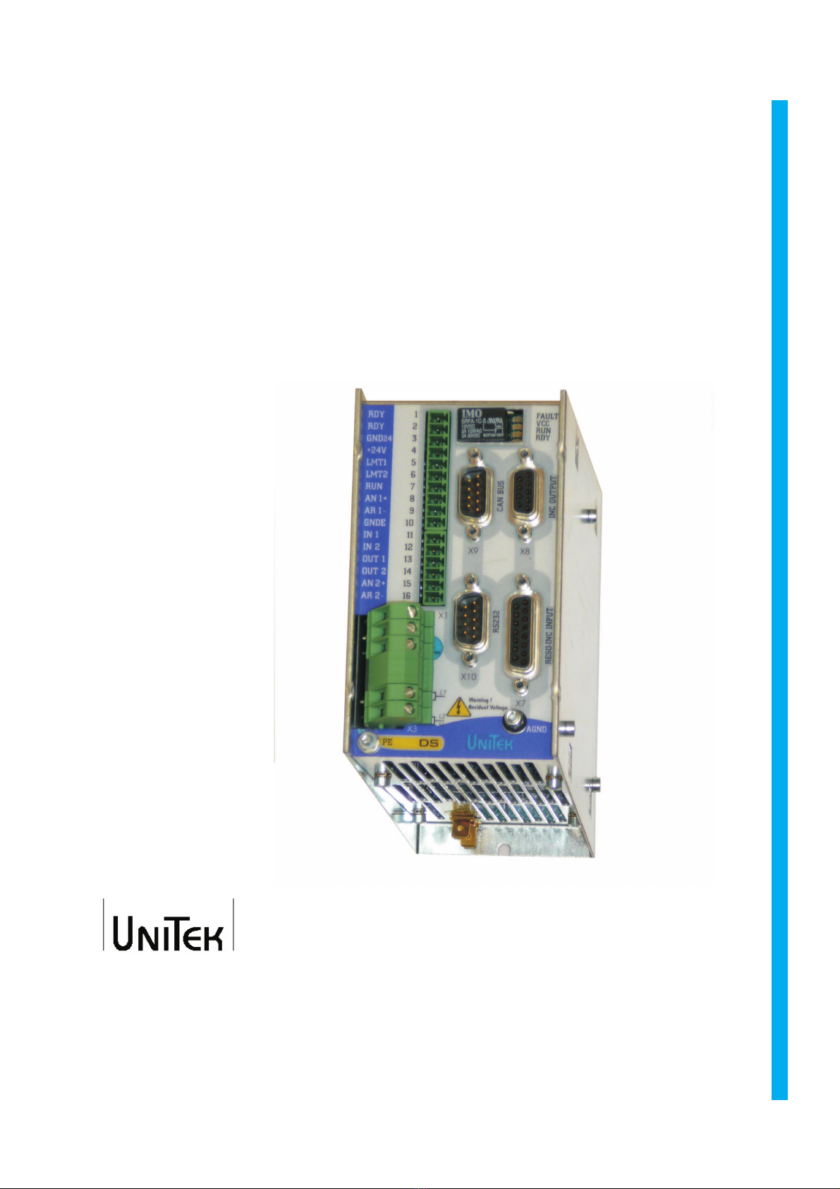
The DS 2420 drives can be used as single-axis position amplifier or torque or speed
amplifier.
The position and speed actual value is generated in the encoder unit (resolver or
incremental encoder). The encoder pulses are emitted from the amplifier for a
superordinate PLC/CNC control. The control circuits of current, speed, and position are PID
controllers which are easy to program. They can be programmed by means of a PC or a
programming box. The communication with superordinate controls is effected by means of
BUS systems (standard CAN-BUS, RS232) or by analogue interfaces.
Note:
The energy is fed back into the battery during brake operation.
No ballast (regen) circuit.
For any operation via a mains supply circuit (without battery) a separate ballast circuit or a
voltage watchdog must be installed.
Information:
Digital servo-amplifiers > UNITEK series DS200, DS400
Analog three-phase servo-amplifiers > UNITEK series TVD3, TVD6, AS
Analog dc servo-amplifiers > UNITEK series TV3, TV6, TVQ6
Thyristor current converters 1Q, 4Q, servo > UNITEK series
Classic
, 200W to 800kW
DC and ac servo-amplifiers for battery operation > UNITEK series BAMO A2, A3, D3
analog and digital series BAMOBIL
General information

6
DS 2420, DS 4820
Applications
Battery-driven machines and installations for all types with a drive power of 1kW especially
as 4Q-servo-drive for
- highly dynamic acceleration and braking cycles
- a wide control range
- a high efficiency
- small motor dimensions
- a uniform, accurate and smooth running
For speed or torque control or combined speed/torque control incorporated within or
independent of position control loops.
Drives with constant speed as in conveyors, spindle drives, pumps, transversal or
longitudinal pitch drives.
Synchronous multiple motor drives.
Synchro-servo-drives are more compact than other electric drives.
Particularly suitable for:
component equipment inserting machines, testing machines, sheet-metal working
machines,
machine tools, plastic working machines, assembly machines,
knitting and sewing machines, textile working machines, grinding machines,
wood and stone working machines, metal working machines, food processing machines,
robots and handling systems, conveyors, extruders, calenders, and
many other machines and installations.
Motor features
- protection rating IP 65
- compact
- suitable for rough surroundings
- suitable for high dynamic overload
- free of maintenance
Note
Brushless drives are used where braking operations are predominant, e.g. when
deceleration is mainly required:
- winding machines, lifts, great centrifugal masses, vehicles
The braking energy is fed to the battery.
For any operation via a mains supply circuit (without battery) a separate ballast circuit or a
voltage watchdog must be installed.
Applications

7
DS 2420, DS 4820
Build
- devices for switch cabinet mounting, steel housing, according to the VDE, DIN and EC
regulations, protection rating IP20, VGB4
- standard digital control electronics
- power electronics for 20A (S1 operation)
- battery power input voltage 24V= or 48V=
- independent 24V chopper power supply unit for the auxiliary voltages
Galvanic isolation
- between the housing and all electric parts
- between the auxiliary voltage connection and the power section and the
control electronics
- between the power section and the control electronics
- between the control electronics and the logic inputs
- the distance of air gaps and leakage paths adhere to the VDE standards
Components
- FET power semi-conductors, comfortably over-dimensioned
- only components customary in trade and industrially standardised are used
- SMD equipment
- LED displays
Characteristics
* EMC protected steel housing
* battery connection 24V= or 48V=
* independent auxiliary voltage connection 24V=
* digital interfaces RS232, CAN-BUS (further option)
* analogue inputs, programmable differential inputs
* digital inputs/outputs, programmable, optically de-coupled
* logic for enable and the output stage switch
* BTB ready for operation, relay contact
* position, speed and torque control
* resolver or incremental encoder (sine encoder option)
* encoder output
* static and dynamic current limiting
* uniform, completely digital control unit
* intrinsically safe and short-circuit proof power section
* processor-independent hardware switch-off in case of short-circuits, circuits to earth,
over-voltage, under-voltage, and over-temperature of the amplifier or the motor
Features

8
DS 2420, DS 4820
Power supply connection Battery 24V= ; Battery 48V=
Auxiliary voltage connection 24V= ±10% / 2A, Residual ripple
<10%,regenerating fuse
Specification Dim. DS2420 DS 4820 DS2420-DC DS 4820-DC
Supply voltage
nominal value V~ 24 48 24 48
Max.output voltage,
Max.nominal value V~eff 3x14 3x32 22 45
Power input S1 max. VA
700
1400 700 1400
Power output S1 max. W
500
1000 500 1000
Continuous current A
eff
20
Max. Peak current A
Io
40
Max. Power loss W
60
65 60 65
Pulse frequency kHz
8
Over-voltage switching
treshold V= 38 66 38 66
under-voltage switching
treshold V=
18
32 18 32
Input fuse A
30
Weight kg
1.2
dimensions h
x
w
x
d mm
140x70x190
Unit size
1
Control signals V A Function Connector
Analog inputs
± 10
0.005 Differential input
X1
Digital inputs ON
OFF 10-
30
<6
0.010
0Optically decoupled
X1
Digital output
+24 0.03
Optically decoupled
X1
Resolver Differential input
X7
Encoder input >3.6V Optically decoupled
X7
Encoder output >4.7 Optically decoupled
X8
CAN interface Optically decoupled
X9
RS232 interface 9600 baud
X10
Technical data

9
DS 2420, DS 4820
Specification
Protection rating IP20, VGB4
standards EN60204,
Operating temperature range 0 to +45
o
C
Extended operating temperature
range +45
o
C to +60
o
C
performace reduced by 2%/
o
C
Storage temperature -30
o
C bis +80
o
C
Humidity rating Class F humidity <85%,
no condensation allowed !
Site of installation £1000m above sea level 100%,
>1000m performace reduced by 2%/100m
Ventilation Internal fans
Mounting position Vertical; performace reduced by 20% when mounted
horizontally
Programming Version Software version Extension
DS-4xx-x RESO- 12bit DRIVE_DS 2.
DS-4xx-x RESO-
12/16bit
DS-4xx-x Encoder -IN
DS-4xx-x Sine encoder -RS
Technical data

10
DS 2420, DS 4820
Free

11
DS 2420, DS 4820
Important instruction
Blank mounting surface, no lacquer (EMC surface-to-surface contact)
Check the device for mechanical damage. Only perfect devices can be mounted.
Disconnect the power supply prior to any assembly.
For installations connected to an electric power supply install the s
horting plug and affix the warning signs.
The device must only mounted by suitably trained personnel.
Vertical mounting position.
Please note that there will be a performance reduction when the d
evices are mounted horizontally (10%).
Ensure that the ventilation is sufficient and that there is enough s
pace for the discharged ventilation air (min. 100mm).
Any bore hole dimensions for the fixation of the device must be taken from the dimension
diagrams or from the drilling plan, not from the device.
Drill the mounting bore holes (M4) into the mounting plate. Turn-in the screws to 4mm.
Insert the device and fasten the screws.
The filter and the choke have to be mounted near to the device.
The line shields and the mounting plate must have surface-to-surface contact.
Unshielded cable heads must be kept as short as possible.
Use vibration-proof screw connections.
Ensure that the switch cabinet ventilation is sufficient.
If the ambient temperature is too high (>30°C) an air conditioning unit has to be installed.
Note: The operation of bedewed devices is not permissible.

12
DS 2420, DS 4820
Control panel
Dimensions
Size 1
DS 2420 to DS 4820
Mounting depth without connector 190 mm
with connector max. 250mm
Fixing screws: M4 x 10 (DIN 912 recommended)

13
DS 2420, DS 4820
Dimensions - Motor choke
Dimensions
Type
Current Induct. Dimensions w.
A mH H x w x d mm kg
MDD 1.6b-10
10 1 95x58x108 1.4
MDD 2b-20 20 0.8 128x80x140 2.6
Motor choke only with a cable shield capacity of >5nF.
Cable length: approx. 25m

14
DS 2420, DS 4820
Mounting
Mounting instruction
Recommended fixing screw
DIN 912 M4x12 with safety washer
Bore threaded M4 holes at a right angle distance
of 312mm.
Drilling template included.
Turn in the M4x12 screws.
Distance to the rear panel of the switch cabinet
approx. 4mm
Position the upper edge of the device (1) and
push it up against the stop (2). Then push the
lower part of the device against the switch
cabinet’s rear panel (3) and lower it (4).
Fasten the screws.
Signal line
Enough space for the discharched ventilation air
Power line
Power line
Size 1 Size 2 Size 3
Signal line
Supply air
Supply air Supply air Supply air
Supply air
In order to achieve good EMC values, it is recommended to use bright, unpainted
mounting plates. The bright surface of the device’s rear panel ensure a good
surface-to-surface contact.
The signal lines and the power supply lines must be routed in separate trunkings with
rectangular crossings (spatial separation of the disturbance coupling).

15
5 Elelectrical Installation
Important note:
The order of the connections to the connector or terminal numbers is obligatory. All further
advice is non-obligatory.
The input and output conductors may be altered or supplemented in accordance with the
electrical standards and guidelines.
Adhere to:
- connection and operating instructions
- local regulations
- EU guideline 89/392/EWG
- VDE and TÜV regulations and Trade body guidelines
Electrical installation should only be carried out when all voltages have been
removed!
Ensure that the device is safely disconnected from the power supply
- place the shorting plug
- affix warning signs
The installation should only be carried out by suitably trained personnel for electrical
engineering.
- Compare the connection data with those indicated on the type plate.
- Ensure that the correct fuses have been provided for the power supply and the auxiliary
voltage.
- Power supply conductors and control lines must be routed separately from
each other.
Connection shields and grounding must be carried out in compliance with
the EMC guidelines. Use the correct line cross-sections.
Type plate (example)
Serial no.
Elelectrical installation
726 3-phase Servo drive
DS 412-RS
Power supply 3 (1 )x 30V~ to 480V~
Rated current 12A eff IP20
Auxiliary voltage 24V=
Fax +49(0)7195/928329 www.unitek-online.de
.
044444

16
5 Elelectrical Installation
Circuit diagram
Core

17
5 Elelectrical Installation
Circuit diagram

18
5 Elelectrical Installation
Connection diagram
Control
Output
stage
switch
Ready
auxiliary
voltage
output
stage
switch
enable
analogue
input 1
digital-
GND
digital
inputs
digital-
outputs
analogue
input 2
system
GND
Detail
page
Battery voltage
K1 Drive contactor
Fx Input fuse
Resolver or
incremental encoder
D-plug with shielded conductor
shield connection in the plug
EMC mass surface-to-surface
contact to the mounting plate
EC
MOTOR
3~
RS/IN
PC
DS 2420, DS 4820

19
5 Elelectrical Installation
Connection diagram -DC
Ready
auxiliary
voltage
output
stage
switch
enable
analogue
input 1
digital-
GND
digital
inputs
digital-
outputs
analogue
input 2
system
GND
EMC mass surface-to-surface
contact to the mounting plate
D-plug with shielded conductor
shield connection in the plug
K1 Drive contactor
Fx Input fuse
RS/IN
DS 2420-DC, DS 4820-DC
PC
Auxiliary voltage 24V=
Control
Tacho,
resolver or
incremental encoder
Tacho

20
5 Elelectrical Installation
Connectors view
Ready
auxiliary voltage
output stage switch
drive enable
analogue input 1
logic zero
digital input
digital output
analogue input 2
Resolver X7
Encoder X7
X3
X1
RS232 X10
Connector on the
solder side
M = connector
FM = input jack
This manual suits for next models
1
Table of contents
Other Unitek Servo Drive manuals