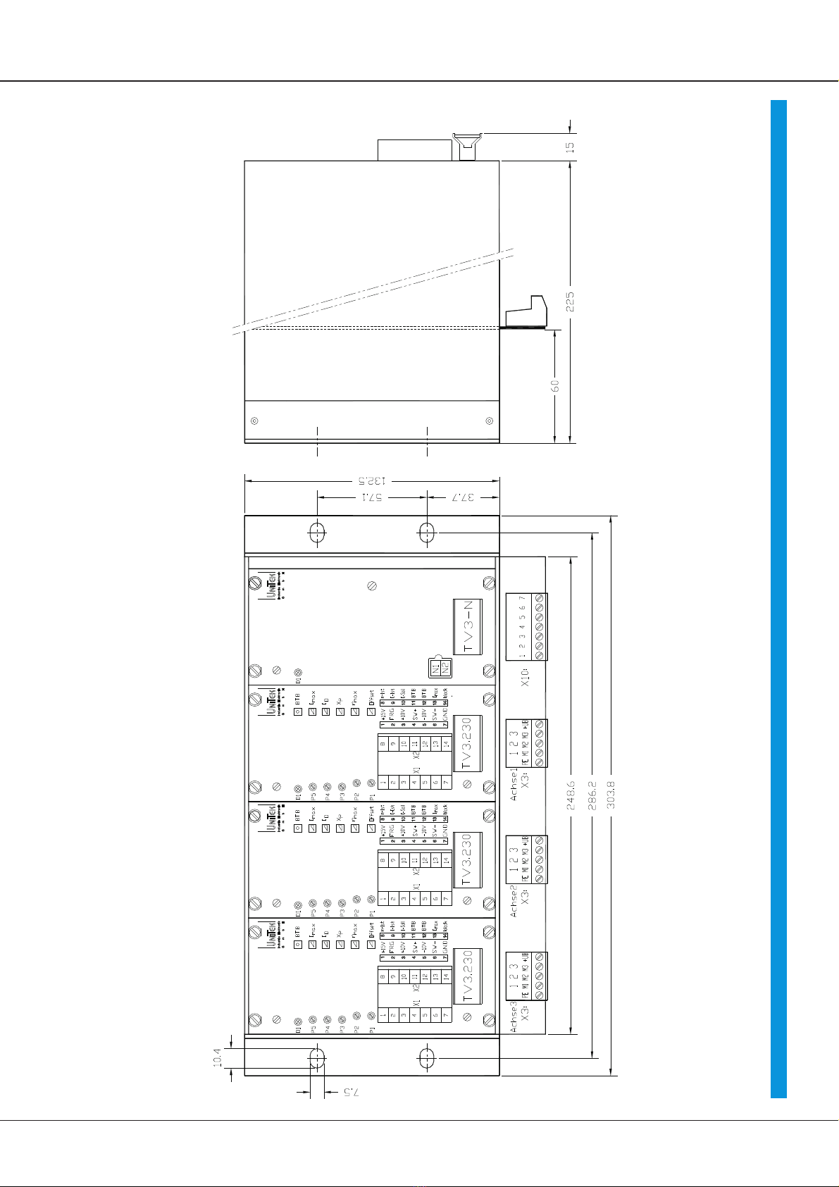
Transistor-Servo-Drive TV3.230
4
General Information
The transistor servo amplifier SERVO-TV3.2 forms together with the direct current
servomotor a propulsion unit distinguished by its high regulating quality
The physical characteristics correspond to those of the direct current motors, that is, the
current is proportional to the torque and the voltage is proportional to the speed. Current
and speed can be measured precisely,
The tachometer actual value is generated from the sensor unit.
(incremental encoder with rotor position track or resolver.)
The analogue regulation circuits of the servo amplifier are designed simply.
In the speed controller (P-I-controller) of the servo-amplifier the nominal value and the
actual value are processed. The result is the current nominal value.
As occurs in all DC-servo-amplifiers which are supplied by the dc-bus ,
the feed-back of the energy must be observed when braking in the dc-bus (especially
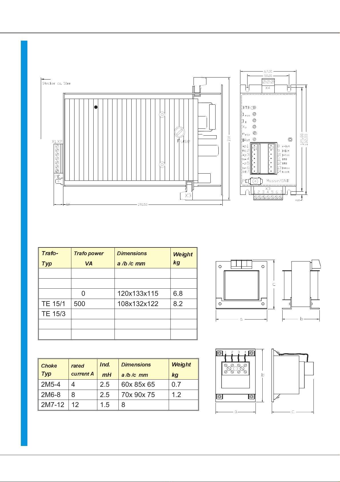
where stroke or eccentric cycles are concerned). The ballast circuit is designed for 3%
on-period, higher cyclic durations can be reached by adding external resistors. (option)
Information:
Further servo-amplifiers for DC-servo-motors
for low power SERVO -DC TV3&TV6 24 ... 120V, 6 ... 12A
for midrange power SERVO -DC TVQ6 up to 250V, 10 ... 25A
for high power Classic Q2, Q6 up to 250V, 15 ..60A
Motor governor for DC-shunt motors
from midrange upto
higher power Classic Q1, Q3 up to 550V, 15 ... 2000A
3-Phase-servo-amplifier analog for AC-synchro-servo motors
for low power SERVO -AC TVD3-2 24 ... 115V, 5 ...10A
SERVO-AC TVD3-230 230V, 5...10A
for midrange power SERVO - AC TVD6-2 200V , 400V, 5 ... 25/40A
for high power SERVO-AC AS250/275, AS450/475
3-Phase-servo-amplifier digital for AC-synchro-servo motors
for low power upto
higher power Digital-AC-SERVO DS 2xx 230V, 5...10A
Digital-AC-SERVO DS 4xx 400V, 5...50A
Battery Drive BAMO C 24V, 10...40A
BAMO A1,A2,A3 24..200V, 10...500A
BAMO D3 (digital) 24..200V, 10...500A
General Information