UniTemp GmbH •Luitpoldstr. 6 •D-85276 Pfaffenhofen • +49 (0) 8441 787663 • www.unitemp.de • info@unitemp.de
Operation Instructions RSS-110-S En Ver. 06.2016 Page 5 of 13
1.2 Regular use of the RSS-110-S system
This RSS-110-S (reflow solder system) is specified for use in laboratories or industrial
facilities use only. For any other use as mentioned in this operation instructions,
UniTemp GmbH does not assume any liability and any warranty claim will expire.
The equipment is NOT to be used for:
any usage which are not defined above, especially the processing of parts,
equipment or gases for which this manual is not foreseen.
the connection of any units or equipment which have electrically active parts.
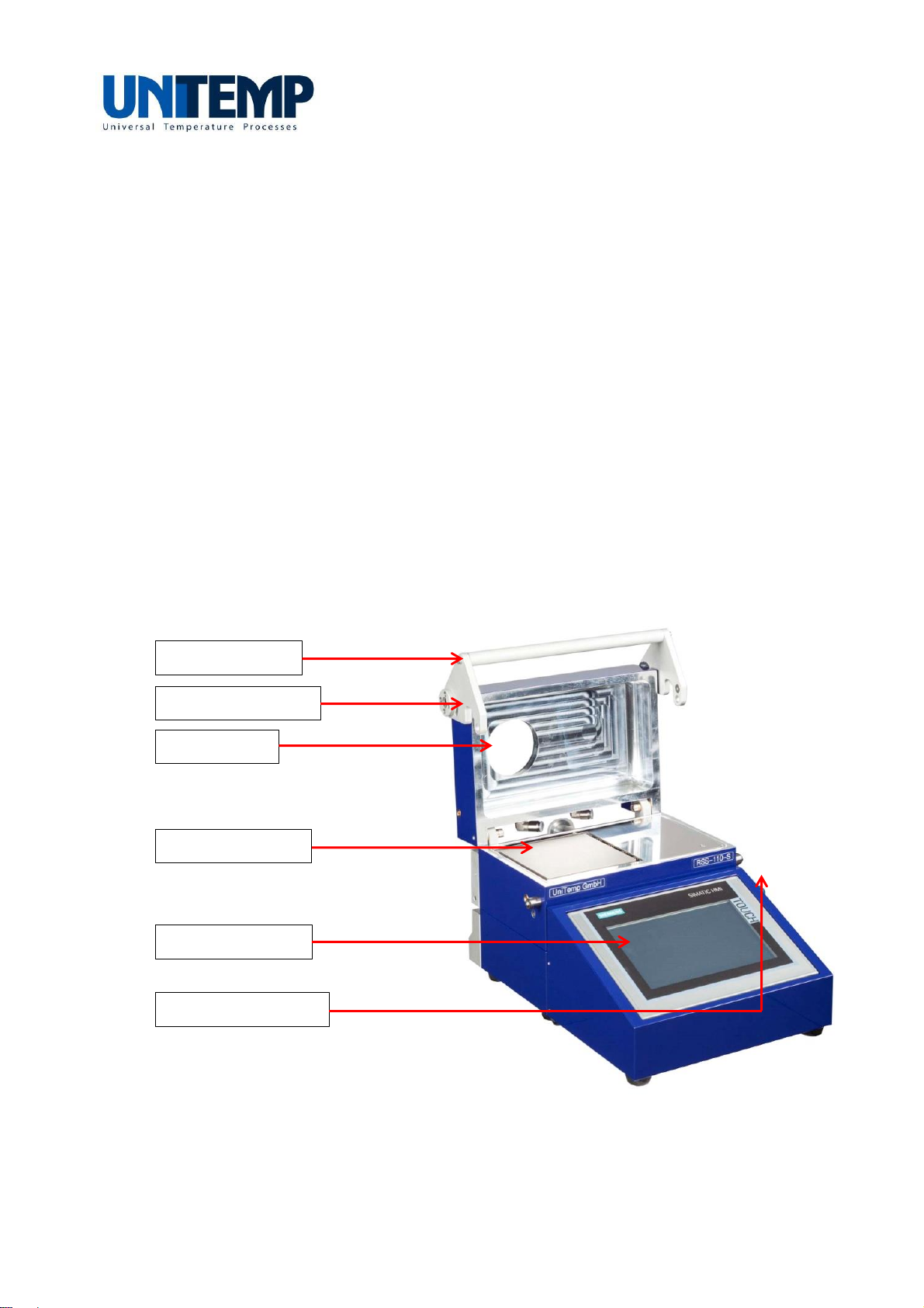
1.3 Description of functions of RSS-110-S system
The process atmosphere is defined by using process gases or vacuum. Delivery, instal-
lation and commissioning are very comfortable to handle. The complete system is very
small and requires only a minimum of space.
The inner walls of process chamber (both on fixed bottom and on hinged cover) are wa-
ter-cooled. The process chamber can be evacuated by vacuum pumps (roughing pump,
e.g. membrane pump or rotary vane pump).
The heating plate inside of process chamber is „hardcoated“ and therefore extremely
stable and scratch-proof. The samples are placed on this heating plate. During cooling
process the heating plate is pneumatically pushed down and brought in contact with
permanently cooled chassis. No pieces may be dropped between heating plate and
chamber because cooling down process could be disturbed permanently and the
heating plate could be damaged.
The marginal thermal mass of the reflow solder system, the heating and the cooling
system allow a controlled heating-up of the samples up to 120 K/min and a cooling
down rate up to 150 K/min (depends on model). An integrated type-K thermocouple
allows accurate temperature measurement. The process control enables the application
of any inert process gas.
Check of the soldering chamber atmosphere
A gas distribution system permits an evenly controlled atmosphere in the process
chamber. The present system is equipped with one process gas line controlled by mass
flow controller enabling a maximum flow of nitrogen (N2) gas of 2 standard liters per
minute (Nlm).
Operation of reflow solder system
Programming and operation of this reflow solder system is done using the touch panel
(Simatic TP700). The touch panel allows storage of 50 programs of up to 50 steps each.
Process data can be stored onto USB 2.0 memory stick or to computer network
(requires integration into network domain). Operation of touch panel is explained in a
separate operation instructions.