Quick TS1300 User manual

TS1300
Lead Free Soldering Station
Instruction Manual
Thank you for purchasing our Lead Free Soldering Station. It is designed for lead free
soldering. Please read this manual before operating the unit. Store this manual in a
safe, easily accessible place for future reference.

1
Contents
Ⅰ. Safety Instruction ................................................................................................................................................. 2
Ⅱ. Summary .............................................................................................................................................................. 4
Ⅲ. Feature ................................................................................................................................................................. 4
Ⅳ. Specifications ....................................................................................................................................................... 5
Ⅴ. Setting & Operating the Soldering Station .......................................................................................................... 5
5.1 Iron Holder and Sponge ............................................................................................................................... 6
5.2 Connection ................................................................................................................................................... 6
5.3Turn on/off .................................................................................................................................................... 7
5.4 Temperature Setting ..................................................................................................................................... 8
Ⅵ. Working Parameters Setting ................................................................................................................................ 8
6.1 Enter into SET menu.................................................................................................................................... 8
6.2 Temperature setting ...................................................................................................................................... 9
6.3 Alarm Temperature+ Setting ........................................................................................................................ 9
6.4 Alarm Temperature- Setting ....................................................................................................................... 10
6.5 Sleep time setting ....................................................................................................................................... 10
6.6 Close time setting .......................................................................................................................................11
6.7 Temperature unit setting ............................................................................................................................ 12
6.8 Key Tone Setting ....................................................................................................................................... 12
6.9 ESD ............................................................................................................................................................ 12
6.10 Address setting ......................................................................................................................................... 13
6.11 Language selection .................................................................................................................................. 13
6.12 Change password ..................................................................................................................................... 14
Ⅶ.Calibrating the Temperature ............................................................................................................................... 15
Ⅷ.Tip Care and Maintenance .................................................................................................................................. 15
Ⅸ.Error messages .................................................................................................................................................... 17

2
Ⅰ. Safety Instruction
CAUTION
When the power is on, the tip’s temperature is very high. The mishandling may lead
to burns or fire, be sure to comply with the following precautions:
Please avoid an abuse of the unit and use the appliance only as the described
manner.
Do not touch the metallic parts near the tip.
Do not use the product near flammable items.
Advise other people in the work area that the unit can reach a very high
temperature and should be considered potentially dangerous.
While replace parts or install tips, turn the power off and allow the unit to cool to
room temperature.
To prevent damage to the unit and ensure a safe working environment, be sure to
comply with the following precautions:
Appliance shall only be used with rated voltage and frequency. (Refer to the
trademark back of equipment.)
Don’t use the appliance if it is damaged, especially the supply cord.
This machine is equipped with a 3-wires grounding plug and must be plugged into
a 3-terminal grounded socket. Do not modify plug or use an ungrounded power
socket. If an extension cord is necessary, use only a 3-wire extension cord that
provides grounding.
Do not use the unit for other applications except soldering.

3
Only use genuine replacement parts.
Do not wet the unit. When your hands are wet, don’t use and disconnect the unit,
or to pull the supply cord.
The soldering process will produce smoke, so make sure the area is well
ventilated.
While using the unit, don’t do anything which may cause bodily harm or physical
damage.

4
Ⅱ. Summary
The soldering station’s temperature adopts LCD double temperature display
and digital calibration, shortcut and convenience. The temperature induction is very
exact and sensitive, the speed of heating and recovery of temperature is very fast, and
so it is the one of the most perfect tools for lead free soldering.
1. LCD display 2. Touch switch (Power: soft switching)
3. Mounting positioning edge 4. Handle socket
5. Power switch (Hard switching) 6. Power supply socket
7. ESD socket 8. RS485 port
9. 6-pin socket (connect to foot switch) 10. USB port
Ⅲ. Feature
1. Can preset technological parameter of three channels, more practical.
2. Temperature alarm function, temperature unit can be changed (℃/℉).
3. Sensor preposition, real-time monitor temperature of tin, return temperature
rapidly.
1
2
3
4
5
6
7
8
9 10

5
4. Solder tip change convenience.
5. Anti-static device, ESD measuring ability.
Ⅳ. Specifications
Type TS1300
Temperature displaying type LCD
Power consumption 300W
Working voltage ★100~240VAC
Temperature Range 50℃~450℃/122℉~842℉
Operation ambient Temperature(Max) Max 40℃
Tip to Ground Resistance <2 Ω
Tip to Ground Potential <2 mV
Dimension (W×H×D) 190×190×134mm
Weight 2.7 Kg
★Ensure that your power supply data agrees with the information on the nameplate
of the machine!
Suggestion thermometer is QUICK 191/192.
Ⅴ. Setting & Operating the Soldering Station
CAUTION: The supply voltage is consistent with the unit!

6
5.1 Iron Holder and Sponge
CAUTION:
●The sponge is compressed. It will swell when moistened with water. Before using
the station, moisten the sponge with the water and squeeze it dry. Failure to do so
may result in damage to the soldering tip.
●If the sponge becomes dry during working, add appropriate water.
1. Dampen the cleaning sponge with water and then squeeze it dry.
2. Place it in groove of the iron holder base.
3. Add a little water to holder base. The sponge will absorb water to keep the sponge
around it wet at all times.
5.2 Connection
CAUTION:
Be sure to turn off the power switch before connecting or disconnecting the
soldering iron.
1. Connect handle cord to the handle socket (4).
2. Place the soldering iron into the iron holder.
3. Connect power plug to power supply socket (6).
Soldering iron holder
Sponge
Holder base
7
4. Connect ESD socket (7).
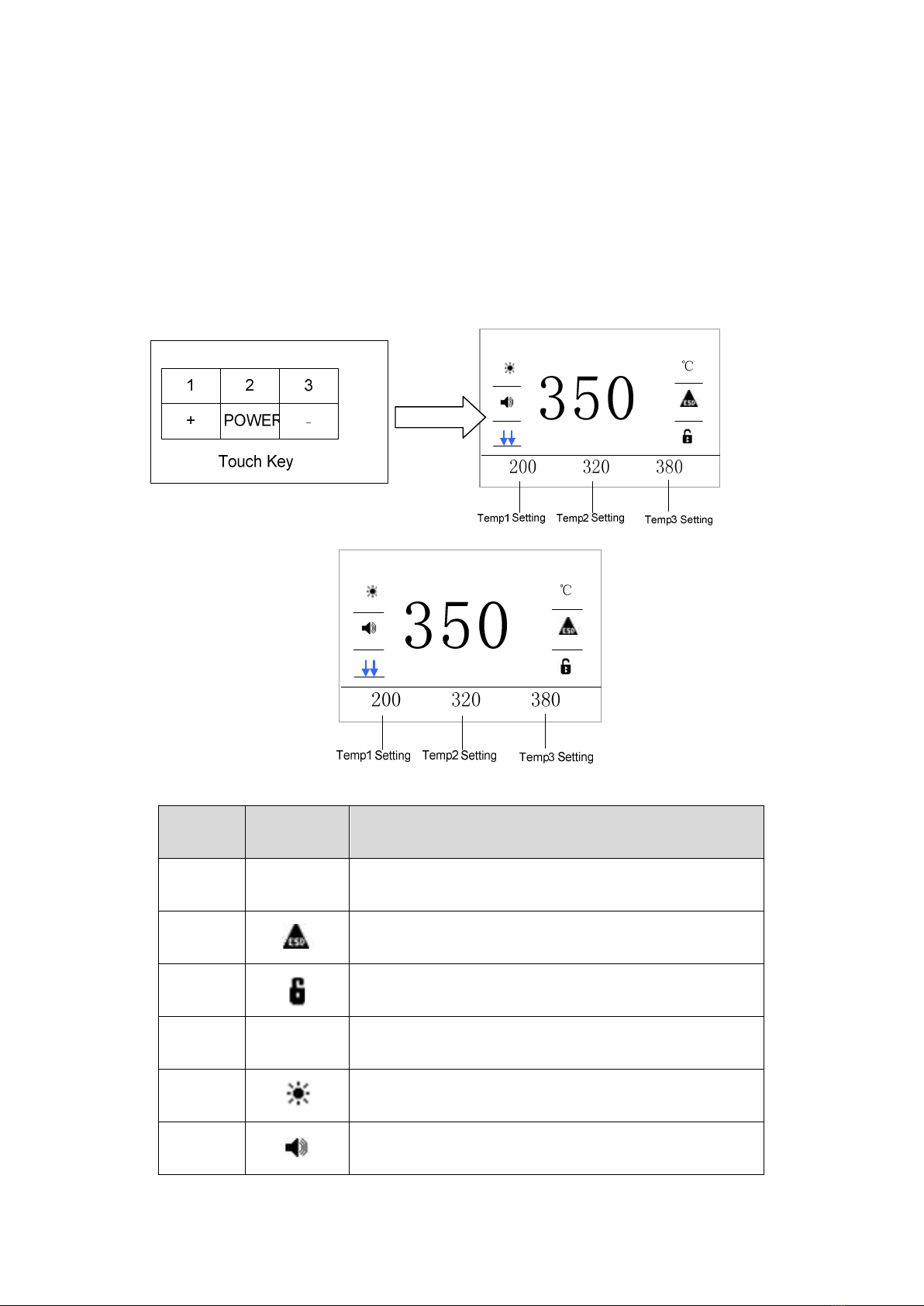
5.3Turn on/off
1. Turn on the power switch (5).
2. Press and hold “POWER” button for 3s to enter main menu.
Item Figure Function
1 ℃ Shows temperature unit (℃/℉)
2 Shows ESD status (ON/OFF)
3 Shows the unit status(Lock/Unlock)
4 350 Display real time temperature
5 Shows Heating element status (ON/OFF)
6 Shows key tone status(ON/OFF)
Press
POWER

8
7
Shows cooling status
Shows heating status
Shows temperature ready
5.4 Temperature Setting
CAUTION:
Make sure the unit is logon (the default password is 000000) and the heater
element is enabled, setting temperature method:
Temperature setting:
1) Press the “+” button once to increase the value by one digit, press and hold it to
continuously increase.
2) Press the “-” button once to decrease the value by one digit, press and hold it to
continuously decrease.
Ⅵ. Working Parameters Setting
6.1 Enter into SET menu
1. Press “2” and “3” buttons for 3s to enter into SET menu.
2. Press “1” (“+”) or “-” button to select menu.

9
3. Press “ENTER” button to enter corresponding menu, see picture.
6.2 Temperature setting
1. Press “ENTER” button to enter into temperature setting menu and blue data is
shown.
2. Press “1” button to select temperature menu, see picture 1(selected Temp1).
3. Press “+” and “-” button to adjust the temperature value, see picture 2.
4. Press “STORE” to save it and press “BACK” to return “Temp1” menu.
6.3 Alarm Temperature+ Setting
1. Press “ENTER” button to enter into menu and blue data is shown.
2. Press “1” button to select status (ON or OFF).
3. Press “+” and “-”button to adjust value (The alarm temperature setting is effective
in the “ON” status).
4. Press “STORE” button to save it and press “BACK” button to return Alarm+ menu,
see picture.
Press
ENTER
Press
“2” &“3”
Figure 1 Figure 2
Table of contents
Other Quick Soldering Gun manuals


Popular Soldering Gun manuals by other brands


Velleman
Velleman HRJA151 user manual

Weller
Weller WSM 1 operating instructions

Vishay Precision Group
Vishay Precision Group Micro-Measurements Mark V Operating and maintaining

ersa
ersa i-CON 1V quick guide

Hakko Electronics
Hakko Electronics FX-100 instruction manual

Weller
Weller WAD 101 operating instructions


