UNITI POWER SYMPHONY SPY6KiRM User manual

2
SAFETY INSTRUCTIONS
KEEP THESE INSTRUCTIONS IN A SAFE PLACE
This manual contains important instructions that should be followed during the installation and
maintenance of the UPS and batteries.
UPS models operate at an optimal temperature of 20-25C
SPECIAL SYMBOLS
RISK OF ELECTRIC SHOCK – observe the warning associated with the risk of electric shock symbol
Important instructions that must always be followed
EU separate collection and lead content mark for lead-acid batteries. This indicates that the battery
must not be disposed of with the ‘normal’ household waste but separately collected and recycled
EU separate collection mark for waste electrical and electronic equipment (WEEE). This indicates that
the item must not be disposed of with the ‘normal’ household waste but separately collected and
recycled
Information, advice, help
Refer to the user manual

3
SAFETY OF PERSONS
•RISK OF VOLTAGE BACKFEED. The system has its own power source (the battery). Isolate the UPS and
check for hazardous voltage upstream and downstream during lockout-tagout operation. Terminal
blocks may be energized even if the system is disconnected from the AC power source.
•Dangerous voltage levels are present within the system. It should be opened exclusively by qualified
service personnel.
•The system must be properly grounded.
•The battery supplied with the system contains small amounts of toxic materials. To avoid accidents,
the directives listed below must be observed:
- Servicing of batteries should be performed or supervised by personnel knowledgeable about batteries
and the required precautions.
- When replacing batteries, replace with the same type and number of batteries or battery packs.
-Do not dispose of batteries in a fire. The batteries may explode.
- Batteries constitute a danger (electrical shock, burns). The short-circuit current may be very high.
•Precautions must be taken for all handling:
- Wear rubber gloves and boots.
- Do not lay tools or metal parts on top of batteries.
- Disconnect charging source prior to connecting or disconnecting battery terminals.
- Determine if battery is inadvertently grounded. If inadvertently grounded, remove source from ground.
Contact with any part of a grounded battery can result in electrical shock. The likelihood of such shock can
be reduced if such grounds are removed during installation and maintenance (applicable to equipment and
remote battery supplies not having a grounded supply circuit).

4
PRODUCT SAFETY
•The UPS connection instructions and operation described in the manual must be followed in the
indicated order
•UPS enclosure IP rating IP20
•CAUTION: To reduce the risk of fire, the unit connects only to a circuit provided with a branch circuit
overcurrent protection of 20A rating, The upstream circuit breaker must be easily accessible
•For PERMANENTLY CONNECTED EQUIPMENT, a readily accessible disconnect device shall be
incorporated externally into the equipment
•For PLUGGABLE EQUIPMENT, the socket outlet shall be installed near the equipment and shall be easily
accessible
•Check that the indications on the rating plate correspond to your AC powered system and to the actual
electrical consumption of all the equipment to be connected to the system
•Never install the system near liquids or in an excessively damp environment
•Never let a foreign body penetrate the system
•Never block the ventilation grates of the system
•Never expose the system to direct sunlight or source of heat
•If the system must be stored before installation, storage must be in a dry place
•The admissible storage temperature range is -25C to +55C without batteries, 0C to +40C with batteries
– it is advised that the batteries are stored below 25C
•This UPS can be used in TN-S/IT/TN-C/TT power systems
•This UPS may be installed with a maximum of 6 external battery modules
SPECIAL PRECAUTIONS
•The unit is heavy: wear safety shoes and suitable lifting equipment
•All handling operations will require at least two people (unpacking, lifting, installation in rack system)
•Before and after the installation, if the UPS remains de-energised for a long period, the UPS must be
energised for a period of 24 hours, at least once every 6 months (for a normal storage temperature of
less than 25C). This charges the battery, thus avoiding possible irreversible damage
•For three-phase AC input installation, this equipment complies with IEC 61000-3-12 provided that the
short-circuit power Ssc is greater than or equal to 3.63MW at the interface point between the user’s
supply and the public system. It is the responsibility of the installer or user of the equipment to ensure,
by consultation with the distribution network operator if necessary, that the equipment is connected
only to a supply with a short-circuit power Ssc greater than or equal to 3.63MW.
•During the replacement of the battery module, it is imperative to use the same type and number of
elements as the original battery module provided with the UPS to maintain an identical level of
performance and safety.
This is a category C3 UPS product. In a residential environment, this product may cause radio
interference, in which case the user may be required to take additional measures.

5
Contents
SAFETY INSTRUCTIONS................................................................................................................................. 2
SPECIAL SYMBOLS ............................................................................................................................................... 2
SAFETY OF PERSONS............................................................................................................................................ 3
PRODUCT SAFETY ................................................................................................................................................ 4
SPECIAL PRECAUTIONS........................................................................................................................................ 4
1. INTRODUCTION.................................................................................................................................. 7
1.1 PRODUCT FEATURES................................................................................................................................. 7
1.2 ENVIRONMENTAL PROTECTION ............................................................................................................... 7
2. PRODUCT OVERVIEW ......................................................................................................................... 8
2.1 WEIGHT AND DIMENSIONS ...................................................................................................................... 8
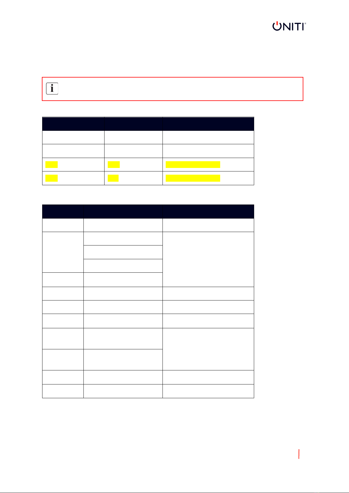
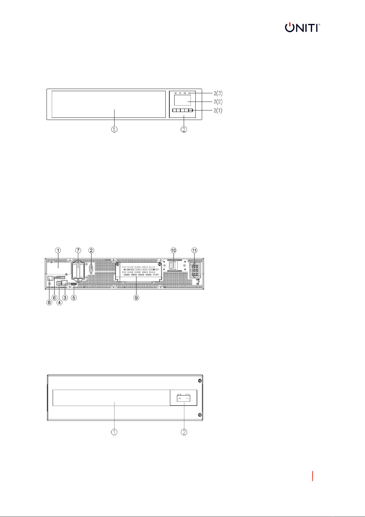
2.2 PRESENTATION......................................................................................................................................... 9
3. INSTALLATION ................................................................................................................................. 11
3.1 UNPACKING &INSPECTING .................................................................................................................... 11
3.2 CHECKING THE ACCESSORY KIT............................................................................................................... 12
3.3 INSTALLATION (UPS)............................................................................................................................... 13
3.4 POWER CABLES CONNECTION................................................................................................................ 15
3.4.1 INPUT/OUTPUT WIRING SPECIFICATIONS....................................................................................... 15
3.4.2 WIRING FOR AC CABLE (AC SOURCE TO UPS).................................................................................. 16
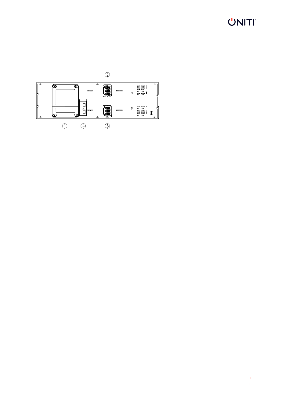
3.4.3 WIRING WITH EXTERNAL BATTERY MODULE (EBM) (DC SOURCE TO UPS) .................................... 17
3.4.4 WIRING WITH MBP ......................................................................................................................... 17
4. PARALLEL SYSTEM INSTALLATION AND OPERATION (OPTIONAL) ...................................................... 18
4.1 WIRING FOR AC CABLE............................................................................................................................ 18
4.2 WIRING FOR PARALLEL SIGNAL CABLE.................................................................................................... 19
4.3 PARALLEL SYSTEM OPERATION .............................................................................................................. 20
5. OPERATION ..................................................................................................................................... 20
5.1 LCD PANEL .............................................................................................................................................. 20
5.2 LCD DESCRIPTION ................................................................................................................................... 22
5.3 DISPLAY FUNCTIONS............................................................................................................................... 24
5.4 USER SETTINGS ....................................................................................................................................... 24
5.5 STARTING THE UPS WITH UTILITY POWER.............................................................................................. 26
5.6 STARTING THE UPS ON BATTERY ............................................................................................................ 26
5.7 UPS SHUTDOWN..................................................................................................................................... 26
6. COMMUNICATION ........................................................................................................................... 27
6.1 RS232 AND USB ...................................................................................................................................... 27
6.2 UPS REMOTE CONTROL FUNCTIONS ...................................................................................................... 27
6.3 IOT .......................................................................................................................................................... 28
6.4 MODBUS TCP.......................................................................................................................................... 28
6.5 INTELLIGENT CARDS (OPTIONAL)............................................................................................................ 28
6.6 UPS MANAGEMENT SOFTWARE............................................................................................................. 29
6.6.1 WINPOWER ..................................................................................................................................... 29
6.6.2 WinPower View App........................................................................................................................ 30
7. UPS MAINTENANCE ......................................................................................................................... 31
7.1 EQUIPMENT CARE .................................................................................................................................. 31

6
7.2 TRANSPORTING THE UPS........................................................................................................................ 31
7.3 STORING THE EQUIPMENT ..................................................................................................................... 31
7.4 REPLACING BATTERIES ........................................................................................................................... 31
7.5 RECYCLE.................................................................................................................................................. 31
8. TROUBLESHOOTING......................................................................................................................... 32
8.1 TYPICAL ALARMS AND FAULTS: .......................................................................................................... 32
8.2 SILENCING THE ALARM........................................................................................................................... 34
9. SPECIFICATIONS ............................................................................................................................... 35
9.1 UPS BLOCK DIAGRAM ............................................................................................................................. 35
9.2 UPS SPECIFICATION ................................................................................................................................ 36

7
1. INTRODUCTION
Thank you for selecting UNITI to protect your electrical equipment.
We recommend that you take the time to read this manual and take full advantage of the many features of
the UPS (uninterruptible power supply).
Before installing the UPS, please read the safety instructions. Then follow the indications in this manual.
1.1 PRODUCT FEATURES
The UPS protects your sensitive equipment from the most common power problems including power
failures, power sags, power surges, brownouts, line noise, high voltage spikes, frequency variations,
switching transients, and harmonic distortion.
Special characteristics:
•Double converter with pure sine waveform output
•Full digital control
•Output PF = 1
•High charger capability, the charger current is up to 12Amps
•Smart charging method to expand battery lifetime
•EBM quantity auto detection
•Communication ports: RPO, Dry in, Dry out, intelligent slot, USB, RS232
•IoT: Ethernet(default) and Wireless (optional)
•Dot-matrix LCD, it supports multi-language
•ECO Mode
•Start-able without battery
1.2 ENVIRONMENTAL PROTECTION
Products are developed according to an eco-design approach
Substances
This product does not contain CFCs, HCFCs or asbestos
Packing
To improve waste treatment and facilitate recycling, separate the various packing components.
•The cardboard we use comprises over 50% of recycled cardboard
•Sacks and bags are made of polyethene
•Packing materials are recyclable
Follow all local regulations for the disposal of packing materials
Product
The product is mainly made up of recyclable materials.
Dismantling and disassembly must take place in compliance with all local regulations concerning waste. At
the end of its service life, the product must be transported to recycling centres, re-use and treatment
facilities for waste electrical and electronic equipment (WEEE).
Battery
The product contains lead-acid batteries that must be processed according to applicable local regulations
concerning batteries.
The battery may be removed to comply with regulations and in view of correct disposal.

8
2. PRODUCT OVERVIEW
2.1 WEIGHT AND DIMENSIONS
The weight in this table is for reference only, please see the labels on the carton for details
Dimension ‘D’ is chassis only, not including panel.
Description Net Weights (KG) Dimensions: D x W x H (mm)
SPY6KiRM 15.8 540 x 438 x 86.3(2U)
SPY10KiRM 26.2 540 x 438 x 86.3(2U)
EBM 60.5 559 x 438 x 129(3U)
EBM 56.1 559 x 438 x 129(3U)
Optional accessories:
Type Description Remark
RT MBP For 6/10kVA rackmount SPY6KiRM & SPY10KiRM
Intelligent
card
Dry contact card (AS400)
See chapter 6.5
NMC card
MODBUS card (CMC)
EMP
Temperature and
humidity sensors
WLAN WLAN module Wireless connection for IoT
COMM cable RS232 cable For RS232 communication
Parallel kit
For parallel system
installation
See chapter 4
Battery
cable
Battery cable (16 batt) for
UPS connection with
users own EBM
1.8m length
See chapter 3.4.3
Battery cable (20 batt) for
UPS connection with
users own EBM
Rail kit
Rail kit for installing UPS
into rack
See chapter 3.3.2
Gland kit Glad kit for both models

9
2.2 PRESENTATION
SPY6KiRM & SPY10KiRM
Front view
1. Ventilation area
2. LCD module, including 2(1)---button, 2(2)---LCD screen, 2(3)---LED indicator
Rear view
1. Intelligent slot
2. RS232
3. Ethernet port (RJ45, for IoT function)
4. USB
5. Wireless (HDMI, for IoT function)
6. RPO & Dry in / out
EBM
Front view
1. EBM label area
2. EBM label
7. Parallel slot
8. RJ45 (for EBM detection / rack MBP detection)
9. AC input / output port (terminal block)
10. Input breaker (optional)
11. External battery port

10
Rear view
1. Fuse board cover (replace EBM fuse)
2. EBM port 1
3. EBM port 2
4. EBM detection Box (RJ45 port)

11
3. INSTALLATION
It is recommended to move the equipment to the installation site by using a pallet jack or truck before
unpacking.
The system may be installed only by a qualified electrician in accordance with applicable safet regulations.
Boxes may be heavy, please install with at least two people.
3.1 UNPACKING & INSPECTING
Unpacking the unit in a low-temperature environment may cause condensation occurred in and on the cabinet. Do not install
the unit until the inside and outside of the unit are absolutely dry (hazard of electric shock).
If any equipment has been damaged during shipment, keep the shipping cartons and packing materials for the carrier or
place of purchase and file a claim for shipping damage. If you discover damage after acceptance, file a claim for concealed
damage.
UPS:
EBM:
Note:
The cabinet is heavy, please see spec weight provided on the carton/label.
Do not lift the unit’s front panel and rear panel.
Discard or recycle the packaging in a responsible manner or store it for future use.
Packing materials must be disposed in compliance with all local regulations concerning waste.

12
3.2 CHECKING THE ACCESSORY KIT
Description UPS EBM
Battery Cable o √
EBM detection
cable
√
USB cable √
RS232 cable o
Parallel cable O
Tower foot √
Extension plate of
tower foot
√
Rack ear √√
Rack rail kit O o
Quick start (EBM) √
User manual (UPS) √
Note: √-- standard configuration; o – Optional, default is not configured

13
3.3 INSTALLATION (UPS)
These UPS support 2 installation modes: rack installation and tower installation
Always keep 500mm of space behind the UPS rear panel for ventilation.
Do not carry the front / rear panel of the module during installation
Rack installation
The procedure is suitable for 19 inch rack cabinet installation, it is recommended that the depth of the
cabinet be no less than 800mm.
UPS model
Identify the final position and keep 2U space for installation
1. Install the rail kit (if configured). This rail kit is 2U & with screw holes (M5), the depth of the rail kit is
443-773mm.
Fasten the rail kit to the cabinet with 8pcs M5 screws + washers (as below)
2. Install ‘rack ear’ to the unit with M4 screws (flat head)

14
3. Slide the unit into the ‘rail kit’ and ensure the rack mounting screws are tightened
EBM model
Identify the final position and keep 3U space for installation. It is recommended to install below the UPS
1. Install the rail kit (if configured): same as UPS as above
2. Install ‘rack ear’ to the unit by the M4 screws (flat head)
3. Slide the unit into the rail kit and ensure the rack mounting screws are tightened
4.

15
Tower Installation
1. Rotate the LCD screen to the tower position
2. Set up the tower foot, then place the unit on to the tower foot.
EBM
1. Set up the ‘extension plate as below and install the tower foot from UPS.
2. place the UPS & EBM into the tower foot individually: place EBM module to the right of the UPS and
align with the front panel
3.4 POWER CABLES CONNECTION
This chapter introduces how to wire AC IN/OUT cable to UPS in different modes, and connect UPS to EBM
3.4.1 INPUT/OUTPUT WIRING SPECIFICATIONS
Before wring UPS, upstream breaker and backfeed contactor should be configured to avoid power
backfeed to UPS. “Backfeed voltage danger” warning label should be added in backfeed contactor or
device. Before operating, UPS input should cut off, and check all terminals voltage to avoid voltage
dangerous. Backfeed contactor rating current should be larger than UPS rating input current.
Below figures show the wiring system of UPS input and output

16
Danger!
The rated current of the utility power switch must be greater than the UPS input current, otherwise the
utility power switch may be burnt!
Recommended upstream protection and downstream switch:
UPS power rating Upstream circuit breaker Backfeed contactor
Downstream switch
6kVA D curve – 63A 63A 40A
10kVA D curve – 80A 80A
63A
Read the safety instructions regarding backfeed protection requirements. Recommended cable minimum
cross-sectional:
Model 6kVA 10kVA
Protective earthing conductor 10mm2 10mm2
Input L, N cable 6mm210mm2
Output L, N cable 6mm210mm2
Battery cable 6mm210mm2
The length of the output cable is recommended not to exceed 10 meters, otherwise, it may cause radio
interference. If a length of over 10m of output cable is required, please contact the distributor/vendor for
details.
3.4.2 WIRING FOR AC CABLE (AC SOURCE TO UPS)
High leakage current:
Earth connection is essential before connecting supply
This type of connection must be carried out by a qualified electrical person
Before carrying out any connection, check that the upstream protection devices (normal AC source and
bypass AC source are open “O’ (off)
Always connect the ground wire first.
1. Remove the cover of the terminal block
2. Connect the AC cable to the terminal blocks:
For cables well fixed, it is recommended to tie these cables to the convex of the rear panel.

17
3.4.3 WIRING WITH EXTERNAL BATTERY MODULE (EBM) (DC SOURCE TO UPS)
1. Be sure to disconnect the battery cable from the EBM before connecting the battery terminals of
the UPS
2. Make sure the UPS is completely off before connecting or disconnecting the EBM
3. Before connecting the EBM, make sure that the EBM specification is compatible with UPS
configuration.
4. Do not reverse the polarity of the external battery.
Connect with configured EBM:
Connect EBM to UPS with battery cable and EBM detection cable.
Note: Extend runtime with up to 6 EBMs per UPS.
Connect with the user’s own EBM:
Connect EBM to UPS with the battery cable (optional configuration)
Note:
1. If an additional battery cable is needed for installation, it must follow cable specifications and the
maximum length of battery cable is 10 meters.
2. If a length of battery cable over 10 meters is required, please contact the distributor or vendor for
details.
3.4.4 WIRING WITH MBP
BBP is the rackmountable UPS system’s optional module, the UPS can be used with the MBP to implement
the maintenance bypass switching function to ensure that the output of the system is not affected during
UPS maintenance.
See the User Manual of RT MBP for details.

18
4. PARALLEL SYSTEM INSTALLATION AND OPERATION (OPTIONAL)
If your UPS is configured with a parallel function, up to 3 UPS can be connected in parallel to configure a
sharing and redundant output power.
In parallel, the mechanical installation for each module is the same as the single system. For details, please
refer to chapter 3.3.
Parallel system AC cable diagram:
4.1 WIRING FOR AC CABLE
1. Wiring length requirement
When the distance between the load and the parallel UPS is less than 10 meters, the length difference
between the input/output lines of the UPS systems in parallel must be less than 20%
When the distance between the load and the parallel UPS is greater than 20 meters, the length
difference between the input/output lines of the UPS systems in parallel must be less than 5%.
2. In the parallel system, common battery application is not supported. Independent EBM connect to
each UPS, please refer to chapter 3.4.3.
3. Professional installation is required, please set the parallel system in a restricted area.

19
Parallel system:
4.2 WIRING FOR PARALLEL SIGNAL CABLE
Parallel signal cable connection diagram:
Remove the cover of the parallel box, then connect each UPS one by one with the parallel cable, make sure
the cable is screwed to parallel port tightly.
It is recommended to lock the parallel cable as above for preventing the parallel ports suffering an
unexpected pulling force and causing the parallel system fault.

20
4.3 PARALLEL SYSTEM OPERATION
1. Turn on the input breakers for the parallel UPS
2. Pressing the button continuously of one UPS in the system, then the system will start to turn on
and enter line mode.
3. Regulate the output voltage of each UPS separately, and check if the output voltage difference is
less than 0.5V among the parallel system. If the difference is more than 0.5V, the UPS need to be
regulated.
4. If the output voltage difference is less than 0.5V, press the button continuously on one of the
UPS, the system will turn off. Turn off the input breakers for the UPS to shut down. The switch on
the output breakers for all the UPS
5. Turn on the input breakers for the parallel UPS. Press the button continuously on one of the UPS
systems, then the system will start to turn on and enter line mode. The system will work normally
in parallel.
5. OPERATION
5.1 LCD PANEL
The UPS has a five-button graphical LCD screen. It provides useful information about the UPS itself, load
status, events, measurements and settings.
The LED:
Indicator Status Description
Green
on
The UPS is operating normally in Online or High
Efficiency Mode
Orange
on The UPS is in Battery Mode
Orange
on The UPS is in Bypass Mode
Red on
The UPS has an active alarm or fault. See
Chapter 8.1 Troubleshooting for additional
information.
This manual suits for next models
2
Table of contents
Other UNITI UPS manuals
Popular UPS manuals by other brands

Bay Networks
Bay Networks BayStack UPS45 Quick reference guide

Atlantis Land
Atlantis Land OnePower A03-S801 user manual

MGE UPS Systems
MGE UPS Systems Comet EXtreme Series Installation and user manual

ICA
ICA FR Series user manual

Eaton
Eaton 93E Installation and operation manual

CyberPower
CyberPower OL6KERT3UDPM user manual