UNITI SPY1500RMi2U User manual

UNITI POWER SYMPHONY
SPY1500RMi2U &
SPY3000RMi2U
USER MANUAL
A RACKMOUNTABLE UNINTERRUPTIBLE POWER
SUPPLY PROVIDING UNITY POWER AND TRUE
ONLINE DOUBLE CONVERSION
Please visit www.unitipower.com for assistance
THE UNITI
POWER SYMPHONY 1500VA
–
3000VA
Download the app

2
SAFETY INSTRUCTIONS
KEEP THESE INSTRUCTIONS IN A SAFE PLACE
This manual contains important instructions that should be followed during the installation and maintenance of
the UPS and batteries.
UPS models operate at an optimal temperature of 20-25C
CERTIFICATION STANDARDS
•Safety: IEC/EN 62040-1
•EMC: IEC/EN 62040-2
•Performance: IEC/EN 62040-3
•ISO 9001:2015
•ISO: 14001:2015
SPECIAL SYMBOLS
RISK OF ELECTRIC SHOCK – observe the warning associated with the risk of electric shock symbol
Important instructions that must always be followed
EU separate collection and lead content mark for lead-acid batteries. This indicates that the battery must not
be disposed of with the ‘normal’ household waste but separately collected and recycled
EU separate collection mark for waste electrical and electronic equipment (WEEE). This indicates that the
item must not be disposed of with the ‘normal’ household waste but separately collected and recycled
Information, advice, help
Refer to the user manual

3
SAFETY OF PERSONS
•Dangerous voltage levels are present within the system. It should only be opened by qualified service
personnel.
•The system must be properly grounded
•The battery supplied with the system contains small amounts of toxic materials. To avoid accidents, the
instructions listed below must be observed:
oServicing of batteries should be performed by personnel knowledgeable about batteries and the
required precautions
oWhen replacing batteries, replace with the same type and number of batteries or battery packs
oCAUTION: Do not dispose of the batteries in a fire. The batteries may explode. Dispose of used
batteries according to the instructions
oDo not open or damage the batteries. Released electrolyte is harmful to the skin/eyes and may be
toxic
oCAUTION: A battery can present a risk of electric shock and high short circuit current. The following
precautions should be observed when working on batteries:
§Remove watches, rings, or other metal objects
§Use tools with insulated handles
§Wear rubber gloves and boots
§Do not lay tools or metal parts on top of batteries
§Disconnect the charging source before connecting or disconnecting battery terminals
§Determine if the battery is inadvertently grounded. If inadvertently grounded, remove the
source from the ground. Contact with any part of a grounded battery can result in electrical
shock. The likelihood of such shock can be reduced if such ground are removed during
installation and maintenance
§Failed batteries can reach temperatures that exceed the burn thresholds for touchable
surfaces

4
PRODUCT SAFETY
•The UPS connection instructions and operation described in the manual must be followed in the indicated
order
•UPS enclosure IP rating IP20
•CAUTION: To reduce the risk of fire, the unit connects only to a circuit provided with a branch circuit
overcurrent protection of 20A rating, The upstream circuit breaker must be easily accessible
•For PERMANENTLY CONNECTED EQUIPMENT, a readily accessible disconnect device shall be
incorporated externally into the equipment
•For PLUGGABLE EQUIPMENT, the socket outlet shall be installed near the equipment and shall be easily
accessible
•Check that the indications on the rating plate correspond to your AC powered system and to the actual
electrical consumption of all the equipment to be connected to the system
•Never install the system near liquids or in an excessively damp environment
•Never let a foreign body penetrate the system
•Never block the ventilation grates of the system
•Never expose the system to direct sunlight or source of heat
•If the system must be stored before installation, storage must be in a dry place
•The admissible storage temperature range is -25C to +55C without batteries, 0C to +40C with batteries – it is
advised that the batteries are stored below 25C
•This UPS can be used in TN/IT/TT power systems
SPECIAL PRECAUTIONS
•The unit is heavy: wear safety shoes and suitable lifting equipment
•All handling operations will require at least two people (unpacking, lifting, installation in rack system)
•Before and after the installation, if the UPS remains de-energised for a long period, the UPS must be
energised for a period of 24 hours, at least once every 6 months (for a normal storage temperature of less
than 25C). This charges the battery, thus avoiding possible irreversible damage
•During the replacement of the battery module, it is imperative to use the same type and number of elements
as the original battery module provided with the UPS to maintain an identical level of performance and
safety.
This is a category C2 UPS product. In a residential environment, this product may cause radio interference,
in which case the user may be required to take additional measures.

5
Contents
SAFETY INSTRUCTIONS .................................................................................................................................. 2
CERTIFICATION STANDARDS ............................................................................................................................... 2
SPECIAL SYMBOLS ............................................................................................................................................... 2
SAFETY OF PERSONS ........................................................................................................................................... 3
PRODUCT SAFETY ................................................................................................................................................ 4
SPECIAL PRECAUTIONS ....................................................................................................................................... 4
1. INTRODUCTION ................................................................................................................................... 7
1.1 ELECTRONIC EQUIPMENT PROTECTION ................................................................................................... 7
1.2 ENVIRONMENTAL PROTECTION ............................................................................................................... 7
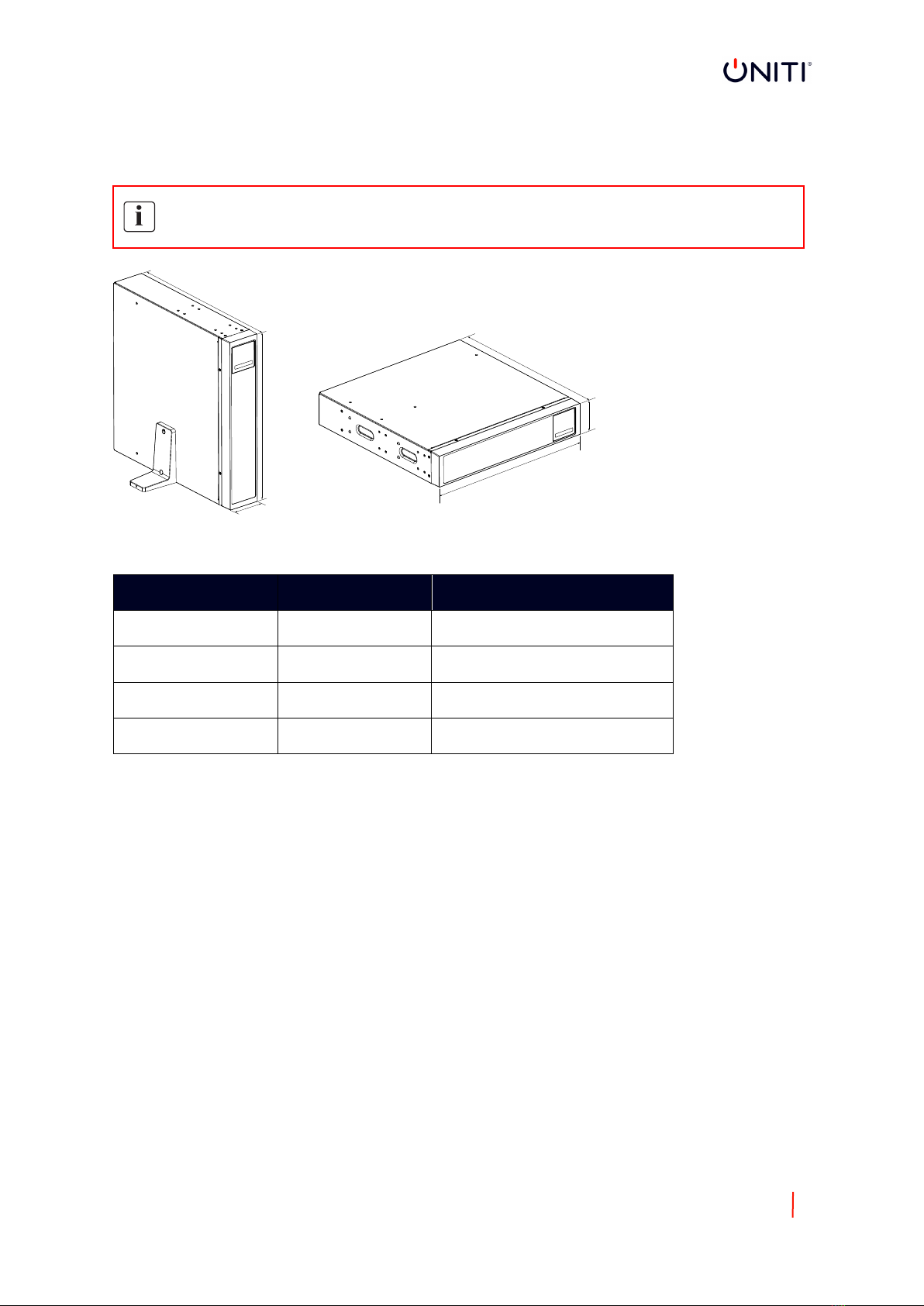
2. PRODUCT OVERVIEW .......................................................................................................................... 8
2.1 WEIGHT AND DIMENSIONS ...................................................................................................................... 8
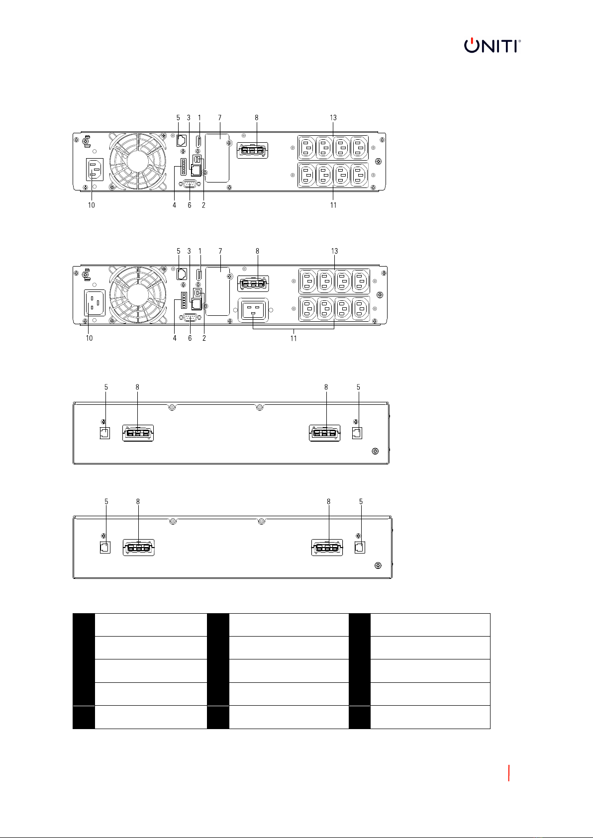
2.2 REAR PANELS ............................................................................................................................................ 9
3. INSTALLATION ................................................................................................................................... 10
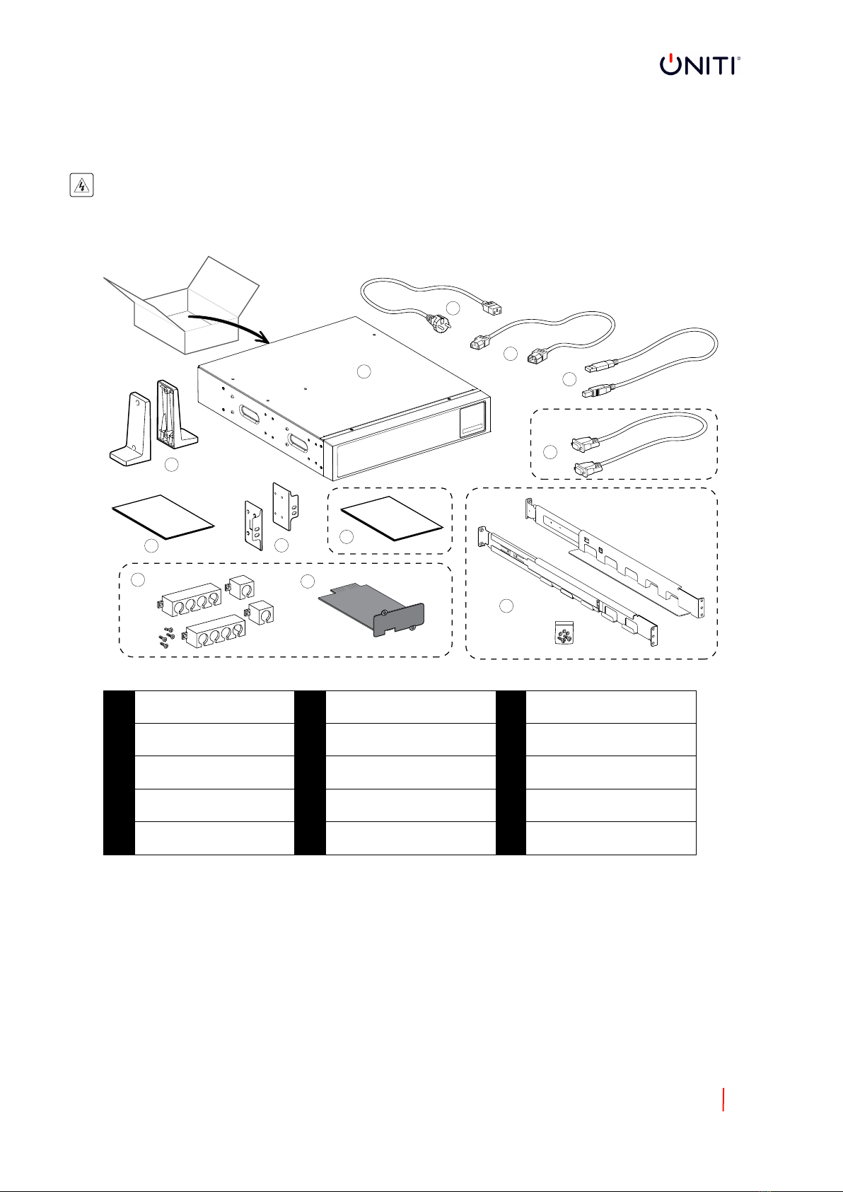
3.1 INSPECTING THE EQUIPMENT ................................................................................................................ 10
3.2 CHECKING THE ACCESSORY KIT .............................................................................................................. 10
3.3 INSTALLATION (UPS) .............................................................................................................................. 11
3.3.1 RT MODELS ..................................................................................................................................... 12
3.4 CONNECTING THE EBM(S) ...................................................................................................................... 13
4. OPERATION ....................................................................................................................................... 14
4.1 LCD PANEL .............................................................................................................................................. 14
4.2 LCD DESCRIPTION ................................................................................................................................... 15
4.3 DISPLAY FUNCTIONS .............................................................................................................................. 17
4.4 USER SETTINGS ...................................................................................................................................... 17
4.5 STARTING THE UPS WITH UTILITY POWER ............................................................................................. 18
4.6 STARTING THE UPS ON BATTERY ............................................................................................................ 19
4.7 UPS SHUTDOWN .................................................................................................................................... 19
5. COMMUNICATION ............................................................................................................................ 20
5.1 RS232 AND USB ...................................................................................................................................... 20
5.2 UPS REMOTE CONTROL FUNCTIONS ...................................................................................................... 20
5.3 IOT .......................................................................................................................................................... 21
5.4 MODBUS TCP ......................................................................................................................................... 22
5.5 INTELLIGENT CARDS (OPTIONAL) ........................................................................................................... 22
5.6 UPS MANAGEMENT SOFTWARE ............................................................................................................ 22
5.6.1 WINPOWER ..................................................................................................................................... 22
5.6.2 WinPower View App ....................................................................................................................... 23
6. UPS MAINTENANCE ........................................................................................................................... 24
6.1 EQUIPMENT CARE .................................................................................................................................. 24
6.2 TRANSPORTING THE UPS ....................................................................................................................... 24
6.3 STORING THE EQUIPMENT ..................................................................................................................... 24
6.4 REPLACING BATTERIES ........................................................................................................................... 24
6.5 RECYCLE ................................................................................................................................................. 24
7. TROUBLESHOOTING .......................................................................................................................... 25
8. SPECIFICATIONS ................................................................................................................................ 26

6
8.1 UPS BLOCK DIAGRAM ............................................................................................................................. 26
8.2 UPS SPECIFICATION ................................................................................................................................ 27

7
1. INTRODUCTION
Thank you for selecting UNITI to protect your electrical equipment.
We recommend that you take the time to read this manual and take full advantage of the many features of the
UPS (uninterruptible power supply).
Before installing the UPS, please read the safety instructions. Then follow the indications in this manual.
1.1 ELECTRONIC EQUIPMENT PROTECTION
The UPS protects your sensitive equipment from the most common power problems including power failures,
power sags, power surges, brownouts, line noise, high voltage spikes, frequency variations, switching transients,
and harmonic distortion.
Special characteristics:
•Online double conversion with pure sine waveform output
•Full digital control
•Higher power density and unity output power factor
•Wider input voltage range: 110Vac-300Vac
•Higher efficiency: 93% for 3Kva, 89% for 1Kva
•Input THDI<5%
•Higher charger current for long backup mode: 8A adjustable from 2A to 8A through LCD screen
•Intelligent EBM quantity detection
•Communication ports: EPO, Dry in, Dry out, intelligent slot, USB, RS232
•IoT: Ethernet (default) and wireless (Optional)
•Dot-matrix LCD supports multi-language
•ECO mode
•Startable without battery
1.2 ENVIRONMENTAL PROTECTION
Products are developed according to an eco-design approach
Substances
This product does not contain CFCs, HCFCs or asbestos
Packing
To improve waste treatment and facilitate recycling, separate the various packing components.
•The cardboard we use comprises over 50% of recycled cardboard
•Sacks and bags are made of polyethene
•Packing materials are recyclable
Follow all local regulations for the disposal of packing materials
Battery
The product contains lead-acid batteries that must be processed according to applicable local regulations
concerning batteries.
The battery may be removed to comply with regulations and in view of correct disposal.

8
2. PRODUCT OVERVIEW
2.1 WEIGHT AND DIMENSIONS
The weights in this table is for reference only, please see the labels on the carton for details
Description
Net Weights (KG)
Dimensions: D x W x H (mm)
SPY1500RMi2U
15.8
445 x 438 x 85.5
SPY3000RMi2U
26.2
600 x 438 x 85.5
EBM3618RT2U
22.6
445 x 438 x 85.5
EBM7218RT2U
39.9
600 x 438 x 85.5
D
D
W
W
H
H

9
2.2 REAR PANELS
SPY1500RMi2U
SPY3000RMi2U
EBM3618RT2U
EBM7718RT2U
Legend
1
WLAN (HDMI)
2
USB
3
Ethernet
4
RPO / Dry in / Dry out
5
EBM auto detection
6
RS232
7
Slot card box
8
EBM connector
9
Input breaker (optional)
10
Input socket / Input
terminal
11
Output socket / output
terminal
12
Output fuse (optional)
13
Programmable output
socket

10
3. INSTALLATION
3.1 INSPECTING THE EQUIPMENT
If any equipment has been damaged during shipment, keep the shipping cartons and packaging materials for the
carrier or place of purchase. Returns policy subject to supplier and not specific to the manufacturer
.
3.2 CHECKING THE ACCESSORY KIT
1
UPS
2
Input cable
3
Output cables
4
USB cable
5
Tower stands
6
User manual (English)
7
Rack ears
8
Cable lockers (optional)
9
Slot card (optional)
10
Rail kit (optional)
11
RS232 cable (optional)
13
User manual (multi-
language) (optional)
5
2
1
3
10
4
6
8
7
9
12
11

11
3.3 INSTALLATION (UPS)
Always keep 200mm of space behind the UPS rear panel for ventilation.
Check that the indications on the name plate located on the top cover of the UPS meets the AC-power source
and the electrical consumption of the total load.
1. Connect the UPS input socket to the AC-power source
using the cable from the protected equipment
2. Connect the loads to the UPS using the output cables
Note: The UPS charges the battery as soon as it is connected to the AC-power source, event if the power button
is not pressed.
Once the UPS is connected to the AC-power source, 72 hours of charging is required before the battery can
supply the rated backup time.
Input terminal and output terminal connection:

12
3.3.1 RT MODELS
Rack installation
Follow steps 1 to 4 for module mounting on the rails.
1
1
2
3
3
4
4

13
Tower Installation
Follow steps 1 to 5 for module mounting on the feet provided.
3.4 CONNECTING THE EBM(S)
A small amount of arcing may occur when connecting an EBM to the UPS. This is normal and will not harm the
user.
Up to 4EBMs can be connected to the UPS.

14
4. OPERATION
4.1 LCD PANEL
The UPS provides useful information about the UPS itself, load status, events, measurements and settings.
Indicator
Status
Description
Green
on
The UPS is operating normally in Online or High
Efficiency Mode
Yellow
on
The UPS is in Battery Mode
Yellow
on
The UPS is in Bypass Mode
Red
on
The UPS has an active alarm or fault. See Chapter
7 Troubleshooting for additional information.

15
The following table shows the indicator status and description:
The button
Function
Illustration
Power on
Press the button for >100ms & <1s to perform a
cold start function (without mains)
Turn on
When mains power is present, press the button for
>1s to turn on the UPS
Turn off
Press the button >3s to turn off the UPS
Scroll up
Press to scroll up the menu
Scroll down
Press to scroll down the menu
Enter menu
Select / Confirm the highlighted option
Exit the present menu
Press to exit current menu to main menu or the
higher-level menu without changing a setting
Mute buzzer
Press the button to mute the buzzer temporarily,
once new working or fault is active, buzzer with
work again
4.2 LCD DESCRIPTION
The LCD backlight automatically dims after 10 minutes of inactivity. Press any button to restore light to the
screen.

16
Operation
status
Cause
Description
Standby mode
The UPS is off without an output
Online mode
The UPS is operating normally and protecting the
critical load
1 beep every 4
seconds
Battery mode
An input failure has occurred, and the UPS is
powering the equipment for shutdown, if possible
1 beep every 1
seconds
Battery mode with battery
low
This warning is approximate, and the actual time to
shutdown may vary significantly
High efficiency mode
Once mains is lost or outside UPS parameters, the
UPS will transfer to online mode or battery mode
and the load is supplied continuously.
Converter mode
The UPS would free run with fixed output frequency
(50Hz or 60Hz)
The load should be derated to 60% in converter
mode.
Bypass mode
An overload or fault has occurred, or a command
has been received, and the UPS is in bypass mode.
Battery test
UPS is undertaking a battery test
Battery fail
The UPS detects low battery voltage, or the battery
has been disconnected
Overload
Too much load attached to UPS output. Remove
any unnecessary items to reduce the total load on
the UPS
Fault mode
A serious fault has occurred which requires urgent
attention

17
4.3 DISPLAY FUNCTIONS
When starting the UPS, the display is in the default UPS status summary screen.
Main menu
Submenu
Display information or menu function
UPS status
UPS mode, IoT status, date/time, battery
status and current alarms (if any)
Event log
Display the events and faults stored
Measurements
[Load] W VA P%, [Input/Output] V,
[Temperature] C
Control
Go to Bypass
Transfers the UPS into Bypass mode
Load segment
Load segment outlets on/off
Start battery test
Starts a manual battery test
Reset event list
Clear active fault
Reset event list
Clear events and faults
Reset com card /
Reset IoT
Reset IoT and Modbus TCP function
inside UPS
Restore factory
settings
Restore to default factory settings
Settings
Refer to Chapter 4.4, User settings
Identification
[Product name], [Serial number],
[firmware revision], [IP/MAC address]
4.4 USER SETTINGS
Submenu
Available settings
Default settings
Password
Can be changed by
user
4732
Change language
English, Italiano,
Français, Deutsch, Español,
Русский, Polski, 简体中文
English
User password
[enabled, ****], [disabled]
Enabled
Audible alarms
[enabled], [disabled]
Enabled
Output voltage
[200V], [208V], [220V],
[230V], [240V]
[230V]
Output frequency
[autosensing], [converter
50Hz, 60Hz]
Autosensing
High efficiency mode
[disabled], [enabled]
Disabled
Auto bypass
[disabled], [enabled]
Disabled
Submenu
Available settings
Default settings

18
Start / Auto restart /
Start from bypass
[disabled], [enabled]
Cold start / auto restart: enabled start
from bypass: disabled
Site wiring fault
[enabled], [disabled]
disabled
Overload pre-alarm
[50% - 105%]
105%
External battery
[Auto detection].
[manual EBM: 0-4],
[Manual Ah: 7-144Ah]
Auto detection 0 EBM
Charger current
[2A], [4A], [6A], [8A] for
long backup
4A
Dry in signal
[disabled], [remote on],
[remote off], [forced
bypass]
Disabled
Dry out signal
[enabled], [disabled]
Bypass
Ambient temperature
alarm
[enabled], [disabled]
Enabled
Battery time
remaining
[enabled], [disabled]
Enabled
Date and time
Dd/mm/yyyy hh:mm
01/01/2020 00:00
LCD contrast
[-5 ~ +5]
[0]
IoT
[enabled], [disabled]
Disabled
Modbus TCP
[enabled], [disabled]
Disabled
If the load is supplied from a transformer, it is recommended to enable the ‘start from bypass’ function.
4.5 STARTING THE UPS WITH UTILITY POWER

19
4.6 STARTING THE UPS ON BATTERY
Before using this feature, the UPS must have been powered by utility power with output enabled at least once.
Battery start can be disabled. Refer to the Chapter 4.4 User setting
4.7 UPS SHUTDOWN

20
5. Communication
5.1 RS232 AND USB
1. Connect a communication cable to the serial or USB port on a computer
2. Connect the other end of the communication cable to the RS232 o USB communication port on the UPS
5.2 UPS REMOTE CONTROL FUNCTIONS
Remote power off (RPO)
When the RPO is activated, the UPS will cut off the output immediately, and continue to alarm.
RPO
Comments
Connector type
16 AWG Maximum wires
External breaker specification
60VDC/30VAC 20mA max
Dry in
Dry in function can be configured (see Settings > Dry in)
Dry out
Comments
Connector type
16 AWG Maximum wires
External breaker specification
60VDC/30VAC 20mA max
Dry out
Dry out is the relay out, dry out function can be configured (see Settings > Dry out)
Dry out
Comments
Connector type
16 AWG Maximum wires
Inner relay specification
24VDC/1A
This manual suits for next models
3
Table of contents
Other UNITI UPS manuals
Popular UPS manuals by other brands

Simpex Electronic
Simpex Electronic MEAN WELL DR-UPS40 installation manual

Digitus
Digitus DN-170120 manual

MGE UPS Systems
MGE UPS Systems PowerServices TelPac installation manual

Falcon
Falcon SG5K-1TX BATTERY REPLACEMENT GUIDE

Powerware
Powerware Prestige series 9 user guide

Emerson
Emerson Liebert NXL installation manual

Tech Novitas
Tech Novitas Propus PPS6KLR user manual

extronics
extronics iUPS101 operating manual

INFOSEC UPS SYSTEM
INFOSEC UPS SYSTEM E3 Live RT Series user guide

MGE UPS Systems
MGE UPS Systems Galaxy 3000 Erratum of installation and user manual

rocpower
rocpower ROCWAVE 1 user manual

Next
Next LOGIX II RT NETPACK 1000VA Installation and user manual