manuals.online logo
Brands
  1. Home
  2. •
  3. Brands
  4. •
  5. Unitor
  6. •
  7. Inverter
  8. •
  9. Unitor UWI-230TP Operating instructions

Unitor UWI-230TP Operating instructions

Ultima modifica/Last Update: 08/10/2015 Rev1.0
UWI-230TP ACDC
Reparation Manual
UWI-230TP AC/DC
PROBLEM
CASE
SOLUTION
The machine does not
switch on.
Lack of power supply
Voltage reaches the machine switch
but there is no voltage after the
contacts.
There is voltage after the
disconnecting switch but the
machine does not go on.
There is voltage after the
disconnecting switch but the
machine does not go on. The
LED L1 is on.
Make sure the line switch is closed, the
protection devices (fuses) are not enabled
and that the power supply cable is in good
condition (Picture 3).
Switch the machine off and disconnect the plug.
Make sure that when the switch is closed,
there is continuity between the contact input
and output (Picture 3) and the varistor is not
broken. If broken, replace board 0074.
(Picture 1).
Switch the machine off and disconnect the plug.
Check the PFC Module on the power board,
if it is damaged, replace the power board
(Picture 2)
You have to check if the LED on rear panel is
on. (Picture 4).You have to check the value
of the main power supply.
The protection devices
of the line set off when
the switch is activated
and the machine does
not go on.
Damaged power supply cable with
short-circuited wires. Inverter is
damaged.
Switch off the machine and disconnect the plug.
Make sure that there are no short circuits
between the poles of the plug caused by a
damaged power supply cable.
Switch off the machine and disconnect the plug,
then check :
- varistor (Picture 1);
if it is damaged, replace the board 0074;
-check the PFC Module and Inverter
(Picture 2,6)
if they are damaged, replace the power board
0070;
Input bridge rectifier (Picture 5);
if it is damaged, verify also inverter and PFC
module.
If they are working then replace only the Input
rectifier, otherwise both.
CAUTION!
Before carrying out any work on the machine
make sure it is off and the plug has been
disconnected.
!
PROBLEM
CASE
SOLUTION
The front panel does
not switch on.
The fan works but the front panel
does not go on.
Switch off the machine and disconnect the plug.
Make sure the flat cable that connects the
front panel to the power board is inserted
correctly. If it is correctly inserted, replace the
front panel, 050.0001.0015.
If the front panel does not go on, check PFC
Module. If it is damaged, replace the power
board (Picture 2,6,15)
The Machine works
and weld but the fan
doesn’t work (too short
thermal cycle).
The cable that connects the Power
Board ( 0070) to the Fan is not
correctly inserted or damaged.
(Picture 8)The fan is
damagedFan speed doesn’t
increase/decrease
Connect the cable or eventually replace it
(Picture 8).
Replace it and if it is still not working, replace
the Power Board.
Replace Power Board 0070
The output voltage in
MMA/TIG is about
13.5V and the
Machine doesn’t weld.
The wires that connect the output
filter board 0075 to the front
panel (0015) are not correctly
connected or damaged.
The cable that connects the
inversion board 0071 to the
module board 0047 is not
correctly connected or is
damaged.
Front panel 0015 cable connected
to the Inversion Board 0071
could be disconnected
Check the follow pieces:Front
panel board 0015 and/orPower
board 0070 and/orInversion
board 0071 are damaged.
Switch off the machine and disconnect the plug:
Connect the cables 0075 or if they are
damaged replace them (Picture 7).
Connect board 71 cable to board 0047, if
damaged replace it.
Connect board 15 cable to board 0071, if
damaged replace it.
Replace damaged Board.
Replace damaged Board
PROBLEM
CASE
SOLUTION
Yellow led on.
Output voltage in each
procedure is about
13.5V. Thermal
protection device
enabled.
Yellow led onThermal protection
device keeps onUsing a
continuity tester verify
if::Protectors are openProtectors
are closedNone of the above
mentioned cases
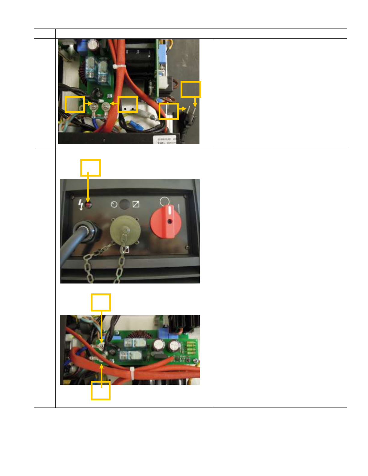
Leave the machine on for few minutes to allow
the cooling of the inverter. Switch the
machine off and disconnect the plug.
Remove the hood and make sure:the
temperature of the heat sink tool is less than
40°C;If it is less than 40°C, check if the
thermal protection connectors are closed.
(Picture 7)They are defective, replace
themCheck that the wires are properly
connected to the weld lead connectors
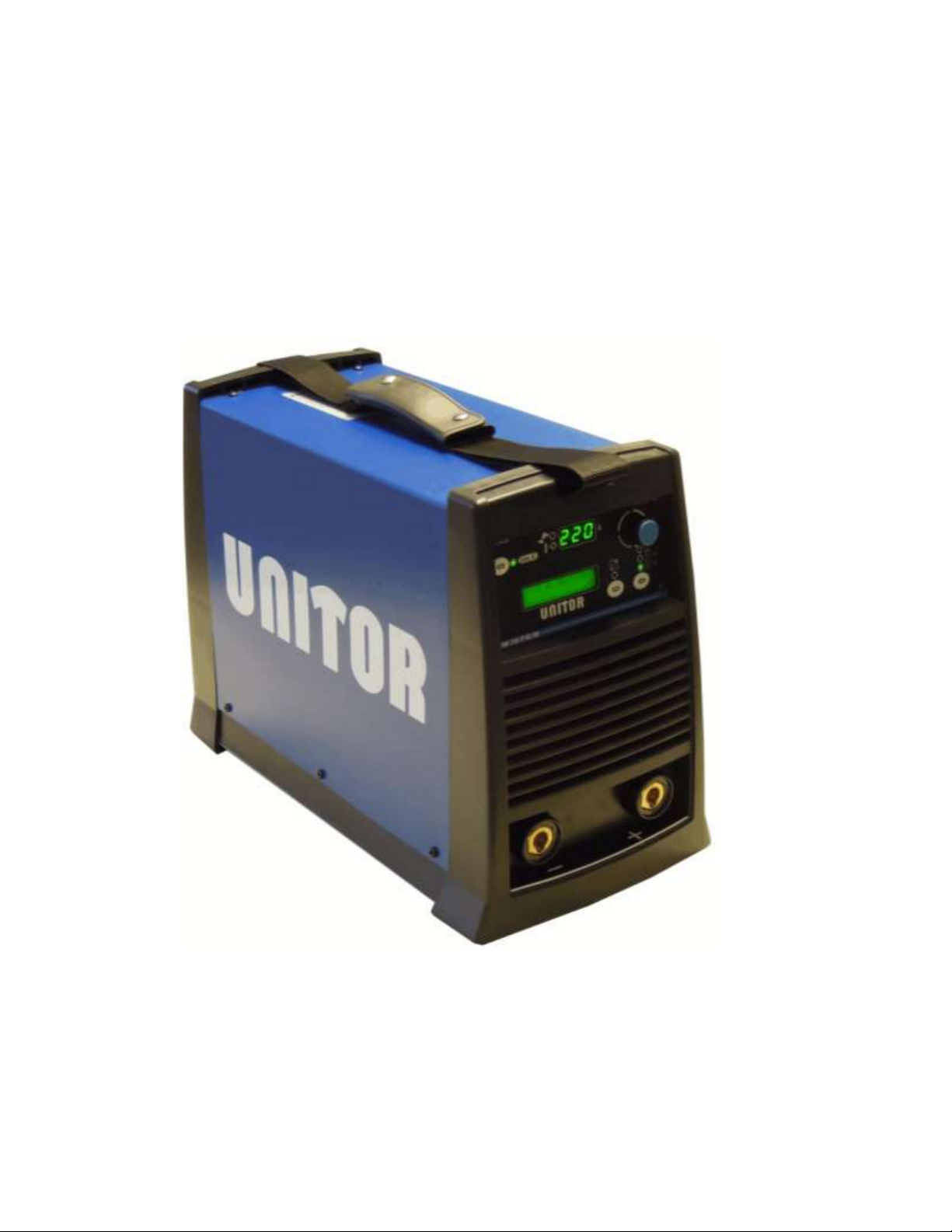
(Picture 7).Erratic feeding in the power board
0070, replace it.
When welding the
protection devices of
the line set off.
Make sure the welding current does
not require greater power than the
one supplied by the line.
Decrease the welding current.
The remote control is
damaged.
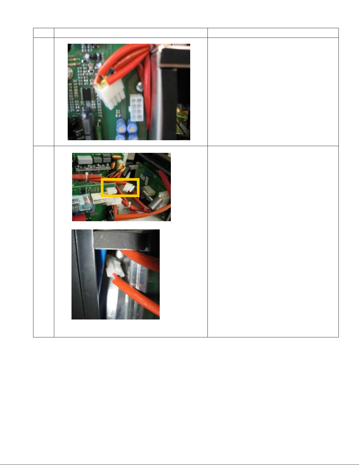
Check that the 4-pin connector
( picture 13) is correctly inserted
on the front panel.The Front
Panel could be damaged.
Insert the wires into the connectors correctly and
insert the connectors into their housings. Should
this not be sufficient, replace the front panel
board 0015
(Picture 12,13)
The machine always
welds at maximum
current.
The Front Panel 0015 is
damaged.The Power Board 0070
is damaged.The Hall Effect is
damaged or the cable is
disconnected.
Switch off the machine and disconnect the
plug:The Front Panel 0015 must be
replaced.The Power Board 0070 must be
replaced.Connect the cable in the right way,
or if damaged, the Hall Effect must be
replaced.
The output voltage in
MMA/TIG is zero and
the welding procedure
is blocked in MMA.
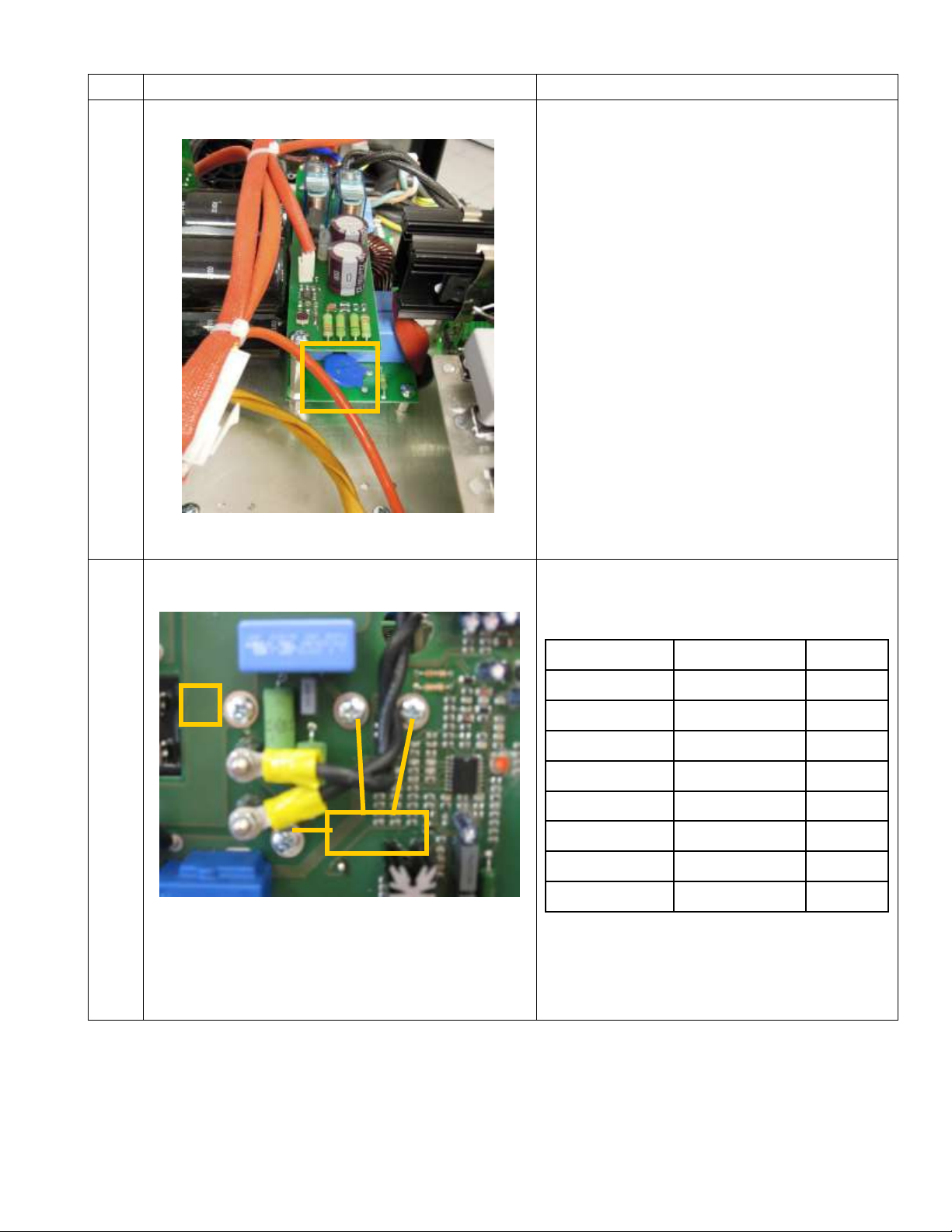
ISOTOP diodes are in short circuit.
The Inversion Module is damaged..
Board 0065 transils damaged
TF POT inductive value is null
Wires Vout damaged
Turn off the machine and remove PCB 0065
(check the ISOTOP diodes):
Replace them (Picture 10)
Replace Module and Board 0071;
Replace Board 0065;
Replace TF POT if damaged.
Checking the wires (Picture 9)
PROBLEM
CASE
SOLUTION
Poor welding quality
Spattering occurs during MMA
welding.
The arc switches off while welding
AC
Make sure welding polarity is correct, the earth
clamp is fixed correctly and check the hot-
start and arc-force values that have to be
decreased if they are too high.
The inversion board 0071 or the front panel
0015 must be replaced.
Other problems
-
You have to reset the front panel.
EXPLANATION
Picture 1
The varistor is a blue disc.
This device is for protecting the board from input
overvoltage. When there is overvoltage they
“explode” causing a short circuit most of the
times. If the extent of the short circuit is very
high, they become an open circuit.
Picture 2
To check the PFC of the switching power supply
unit, carry the following measurements with a
diode tester:
Should there be a short-circuit on one of these
measurements or an “OL” instead of a numeric
value, the power board must be replaced.
Red Probe
Black Probe
Measure
D
S
“OL”
S
D
0.38
G
S
1.02
S
G
1.05
G
D
“OL”
D
G
“OL”
A
D
“OL”
D
A
0.34
D S G
A
EXPLANATION
Picture 3
Check the power supply cable and the mains
switch.
You have to disconnect the machine to the main
power supply and switch on the main switch
(position “I”).
Now you have to check the continuity, with a
diode tester, between points D1-F1 and D2—F2.
If there is no continuity, you have to check the
single parts
Picture 4
If you see L1 ON, the OVERCAT is working.
Check the main power line.
Open the machine, switch on the power and
check between D1 and D2.
If there will be more then 275Vac, you have to
check the main power line.
F1
D1
F2
D2
L1
D1
D2
EXPLANATION
Picture 5
Input bridge rectifier.
To check the Input bridge rectifier , carry out the
following measurements with a diode tester:
Should there be a short circuit on one of these
measurements, the input bridge rectifier must be
replaced.
Rheofore
Probe
Rheofore
Probe
F+
Rosso
D1-D2
Nero
F-
Rosso
D1-D2
Nero
F+
Nero
D1-D2
Rosso
F-
Nero
D1-D2
Rosso
Picture 6
To check the inverter, carry out the following
measurements with a diode tester:
Should there be a short-circuit on one of these
measurements or an “OL” instead of a numeric
value, the power board must be replaced.
Red Probe
Black Probe
Measure
S
G
>2.00
G
S
>2.00
G
G
G
G
S
S
S
EXPLANATION
Picture 7
Make sure the two terminals of the thermal
devices are well inserted in the 8-pin white
connector on the power board 0070.
Picture 8
Make sure that the fan cables +24 V are correctly
inserted:
2-pin connector on the power board;
2-pin connector on the fan.
EXPLANATION
Picture 9
You have to check the Vout cable.
Red Probe
Black Probe
Measure
Pin 4
of the amphenol
Negative
Socket
“OL”
Pin 8
of the amphenol
Positive
shocket
“OL”
Make sure that the output filter board 0074
cables are correctly inserted in the front panel
connectors (board 0015).
EXPLANATION
Picture 10
To check diodes remove the snubber board and carry out
the following measures with a diode tester:
Copper bar
Probe
Copper bar
Probe
Measure
SX
red
UP/DOWN
black
0.3
SX
black
UP/DOWN
red
“OL”
DX
red
UP/DOWN
black
“OL”
DX
black
UP/DOWN
red
0.3
At the ends of the two transils (see below) positioned on the
snubber board, “OL” must always be measured.
Check the diodes
Copper bar
Probe
Copper bar
Probe
Measure
SX
red
OUT
black
0.3
SX
black
OUT
red
“OL”
DX
red
OUT
black
“OL”
DX
black
OUT
red
0.3
UP
SX
DX
DOWN
OUT
DX
SX
EXPLANATION
Picture 11
Press S1 and S3 while switching on the machine until
appears MEMORY RESETTING.
Picture 12
Check continuity, with a diode tester, between points A-Y of
the power board and B-X poles of the connector that goes
to the front panel.
Connect the MINIFIT 4 PINS at the power board, switch on
the machine and check between Y-X if there is +24Vdc.
S1
S2
S3
EXPLANATION
Picture 13
Checking the remote cable.
With a tester (diode mode) check the data table follow.
Probe red
Probe black
Misura
C
9
“OL”
D
4
“OL”
E
3
“OL”
Picture 14
Check if the flat cable has a good connection in the power
board.
R1

Popular Inverter manuals by other brands

HQ Power PSI1000 user manual

HQ Power

HQ Power PSI1000 user manual

Tripp Lite PowerVerter APSX6048VR owner's manual

Tripp Lite

Tripp Lite PowerVerter APSX6048VR owner's manual

Tripp Lite PowerVerter APS1524 Features & specifications

Tripp Lite

Tripp Lite PowerVerter APS1524 Features & specifications

Tripp Lite EMS1012UL Features & specifications

Tripp Lite

Tripp Lite EMS1012UL Features & specifications

CanadianSolar CS1V-MS installation manual

CanadianSolar

CanadianSolar CS1V-MS installation manual

KStar KSG-10K user manual

KStar

KStar KSG-10K user manual

MQ Power EGC-500C Specifications

MQ Power

MQ Power EGC-500C Specifications

GOAL ZERO Yeti 400 Lithium user guide

GOAL ZERO

GOAL ZERO Yeti 400 Lithium user guide

FRO­NIUS 10.0-3 208-240 installation instructions

FRO­NIUS

FRO­NIUS 10.0-3 208-240 installation instructions

Delta REG2000 Series user manual

Delta

Delta REG2000 Series user manual

CO/Tech ig2400s Original instructions

CO/Tech

CO/Tech ig2400s Original instructions

SUNGOLD POWER BluePower SP6548 user manual

SUNGOLD POWER

SUNGOLD POWER BluePower SP6548 user manual

Refu sol 40K Installation and operating manual

Refu sol

Refu sol 40K Installation and operating manual

Power Bright XR250 owner's guide

Power Bright

Power Bright XR250 owner's guide

FRO­NIUS IG-TL 3.0 operating instructions

FRO­NIUS

FRO­NIUS IG-TL 3.0 operating instructions

FRO­NIUS Symo Hybrid 3.0-3-S operating instructions

FRO­NIUS

FRO­NIUS Symo Hybrid 3.0-3-S operating instructions

Tripp Lite UT Series owner's manual

Tripp Lite

Tripp Lite UT Series owner's manual

MQ Power DCA220SSJU4F Operation manual

MQ Power

MQ Power DCA220SSJU4F Operation manual

manuals.online logo
manuals.online logoBrands
  • About & Mission
  • Contact us
  • Privacy Policy
  • Terms and Conditions

Copyright 2025 Manuals.Online. All Rights Reserved.