Power Bright XR250 User manual

Owner's Guide
Printed in China
Toll Free 1 866 295 6775
www.PowerBright.com
XR250
XR400
XR750

2 Important Safety Information
Misusing or incorrectly connecting theXR250/400/750
may damage the equipment or create hazardous
conditions for users. Read the following safety
instructions and pay special attention to all Caution
and Warning statements in the guide.
Warnings identify conditions that may result in
personal injury or loss of life.
Cautions identify conditions or practices that may
damage the unit or other equipment.
1 Introduction
Thank you for purchasing the PowerBright®XR250/400/750
Connected to the 12 volt outlet in your vehicle, the
efficiently and reliably powers a widevariety
of loads through both the AC outlet and USB port.
Read this guide before connecting or using the
XR250/400/750 and save it for future reference.
We hope you enjoy using your and if you
require any assistance, please contact our help desk:
www.PowerBright.com or toll free: 1.866.295.6775
XR250/400/750
XR250/400/750
1
WARNING
Keep children away from the XR250/400/750. The
inverter generates the same potentially lethal AC
power as a normal household wall outlet.

2
The XR250/400/750 housing may become
uncomfortably warm, reaching 140° F (60° C) under
extended high power operation. During operation,
keep it away from materials that may be affected by
high temperatures.
Do not use the XR250/400/750 in the presence of
flammable fumes or gases, such as in the bilge of a
gasoline powered boat, ornear propane tanks. Do
not use the XR250/400/750 in an enclosure
containing automotive-type, lead-acid batteries.
These batteries, unlike sealed batteries, vent
explosive hydrogen gas, which can be ignited by
sparks from electrical connections.
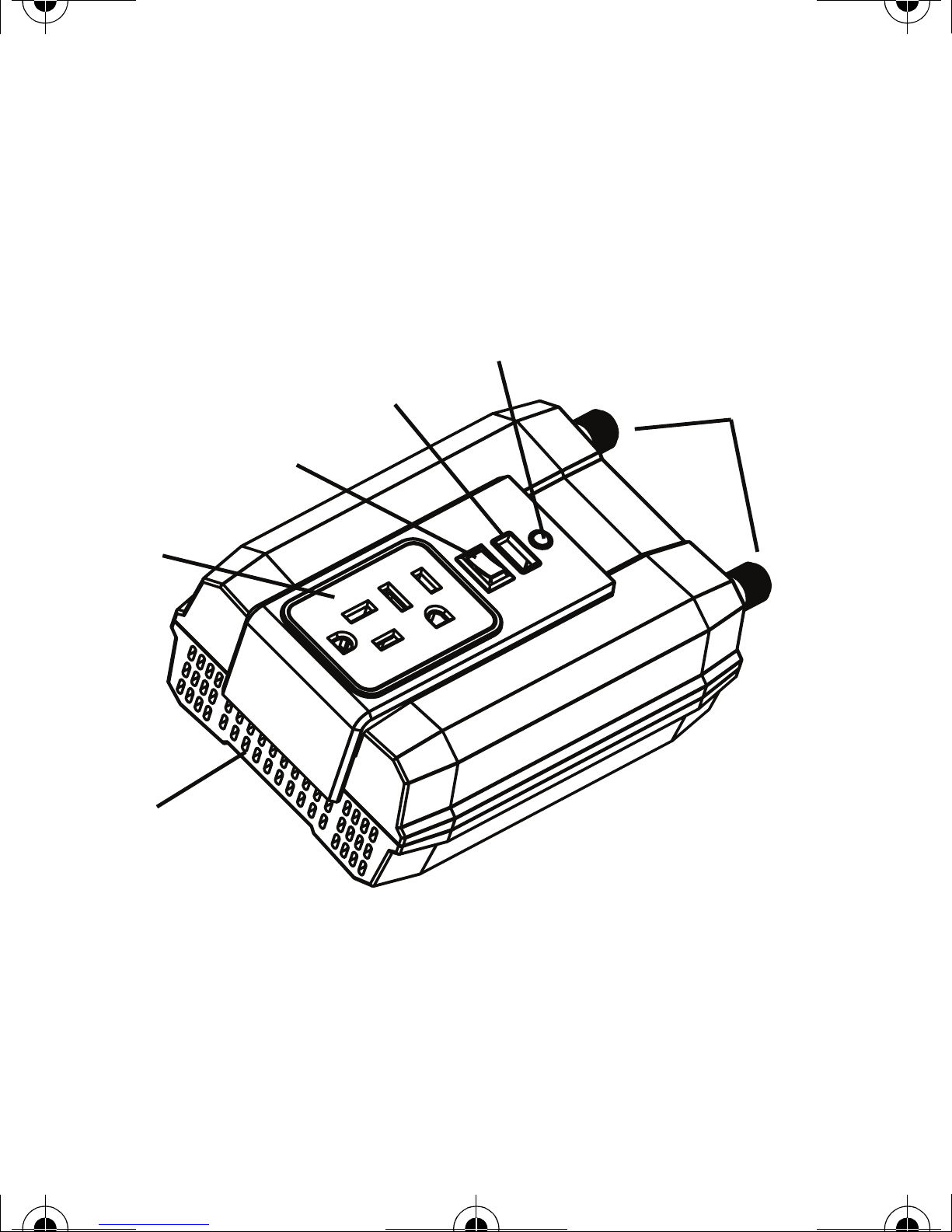
Warnings and Cautions
WARNING: Shock hazard
Use caution when inserting an AC plug into the
three-prong AC outlet. The prongs of an AC plug
can become bent from misuse. If an AC plug is
improperly inserted into the AC outlet, a bent prong
can slip outside the inverter and become a shock
hazard.
Grip the inverter carefully when inserting or
removing an AC plug. Keep your fingers clear of
the AC outlet. Ensure that your fingers do not
contact the prongs of an AC plug when the plug is
partially inside the inverter.

3
CAUTION: Output non-sinusoidal
Some chargers for small nickel-cadmium batteries
can be damaged if connected to theXR250/400/750
Do not use the inverter with the following
appliances:
• Small battery-operated appliances like
rechargeable flashlights, some rechargeable
shavers, and night lights that are plugged
directly into an AC receptacle to recharge.
• Battery chargers used in hand power tools.
These chargers display a warning label stating
that dangerous voltages are present at the
charger battery terminals.
CAUTION
Do not connect live AC power to the XR250/400/750
AC outlets. This will damage the inverter,
and the damage is not covered by warranty.
Do not connect any AC load that has its neutral
conductor connected to ground to the
XR250/400/750

4
Additional Safety Guidelines
• Do not insert foreign objects in the
XR250/400/750outlets or other openings.
• Never connect the inverter to power utility AC
distribution wiring.
• Do not use the XR250/400/750 in temperatures
over 100° F (40° C).
• Do not expose the XR250/400/750 to water, rain,
snow, or spray.
Failure to follow these safety guidelines may cause
personal injury and/or damage to the XR250/400/750
It may also void your product warranty.
3 Safety Features
• Overload protection with automatic shutdown
• Low battery voltage shutdown
• High-input voltage protection with automatic
shutdown
• Overheat protection with automatic shutdown
• Output short circuit protection.

5
4 Inverter Features
Figure 1
Features and Accessories
PowerBright® XR250/400/750
Power/Fault light
USB port Power input Terminals
On/Off Switch
AC Outlets
Ventilation openings

6
5 Using the Inverter
Through its AC outlet, theXR250/400/750is capable
of powering most 120V AC products that use250W/
400W/750W or less. The XR250/400/750 can also
power or chargemost consumer electronics that have
USB power ports.
The XR250/400/750 AC output waveform, called
“modified sine wave” is designed to function
similarly to the sine wave shape of utility power.
Mostdevicesarenotaffected by a "modified sine
wave",youmayneedtoconsult with the manufacture
ofthedeviceyouwish to run prior to connection
withinverter.
Using the DC Cable with Cigarette
Lighter Plug
Due to the limitations of 12V outlets in vehicles or
boats, theXR250/400/750 should only be used to
supply AC power to products that require
250W/400W/750W or less.

7
2. Insert the cigarette lighter plug into the 12 V
outlet.
1. Plug the DC cable into the DC cable port on the
XR250/400/750. Observe correct polarity.
3. Plug the device you want to operate into the
XR250/400/750
4. Whentheinverterisnotinuse,unplugitfromthe
12V outlet to prevent slight discharge of the
battery.
CAUTION: Reverse polarity damage
When plugging in the DC cable, ensure that the plug
aligns with the DC cable port. Failure to do so will
result in reverse polarity and a blown fuse.

8
6 Inverter Operation
1. When properly connectedto a 12V outlet, and
when the
ON/OFF switch is in theON position, the
light will glow BLUE, indicating the inverter is
ready.
2. Plug the product(s) you want to operate into the
AC outlet or USB port and switch them on (if
necessary).
Operating Guidelines
• As the battery is used, its voltage begins to fall.
When the XR250/400/750 senses that the voltage
atitsDCinputhasdroppedto10.5V,theinverter
automaticallyshutsdownandthelightglows RED,
indicating a fault. This prevents the battery from
being damaged. Turn off any devices that the
XR250/400/750 is powering.

9
• If an AC product rated higher than 250/400/750 is
plugged into the XR250/400/750, the inverter will
shut down. The RED FAULT light comes on.
• If the XR250/400/750exceeds a safe operating
temperature, due to insufficient ventilation or a
high-temperature environment, it automatically
shuts down. The RED FAULT light comes on.
• Should a defective battery charging system cause
the battery voltage to rise to dangerously high
levels, the XR250/400/750automatically shuts
down. The RED FAULT light comes on.
Important:
Vehicle batteries are designed to provide
brief periods of very high current needed for engine
starting. They are not intended for constant deep discharge.
Regularly operating the XR250/400/750from a vehicle
battery until low-voltage shutdown occurs will shorten the
life of the battery.

10
• In the event of an overload, low battery voltage or
overheating, the XR250/400/750automatically
shuts down.
Battery Operating Time
Operating time will vary depending on the charge
level of the battery, its capacity and the power level
drawn by the particular AC load, USB load, or
combination of both. Witha typical vehicle battery
and a 80W load, an operating time of 4 to 5 hours or
more can be expected.
When using a vehicle battery as a power source, it is
strongly recommended to start the vehicle every hour
ortwotorechargethebatterybeforeitscapacitydrops
too low. The XR250/400/750 can operate while the
CAUTION
Although the XR250/400/750 incorporates
protection against over-voltage, it may still be
damaged if the inputvoltage exceeds 16 V.
engine is running, but the normal voltage drop that
occurs during starting of the engine may trigger the
inverter’s low voltage shutdown feature.

11
Interference with Electronic Equipment
Generally, most AC products operate with XR250/400/750
just as they would with household AC power.
Below is information concerning two possible
exceptions.
Buzzing sound in audio systems and radios
Some inexpensive stereo systems and AM-FM radios
have inadequate internal power supply filtering and
will “buzz” slightly when poweredby the XR250/400
/750. Generally,theonlysolutionisanaudioproduct
witha higher quality filter.
Television interference
The XR250/400/750is shielded to minimize its
interference with TV signals. However, with weak TV
signals interference may be visible in the form of lines
scrolling across the screen. The following should
minimize or eliminate the problem:
• Increase the distance between theXR250/400/750
and the TV, antenna and cables.
• Adjust the orientation of the XR250/400/750,
television, antenna and cables.
• Maximize TV signal strength by using a better
antenna and use shielded antenna cable where
possible.

12
7 Troubleshooting
PROBLEM: AC product will not operate, no inverter
lights are ON.
PROBLEM: Measured inverter output is too low.
Possible cause Solution
Battery is defective. Check battery and replace if
required.
Loose connections. Check connections.
Possible cause Solution
Standard “average-
reading” AC voltmeter
used to measure output
voltage, resulting in an
apparent reading 5 to 15 V
too low.
Inverter’s “modified sine
wave” output requires “true
RMS” voltmeter for accurate
measurements.

13
PROBLEM: AC product will not operate, RED FAULT
light ON.
Battery voltage is too low. Recharge battery.
Possible cause Solution
AC product(s) connected
are rated at more than the
inverter’s continuous
power rating; overload
shutdown has occurred.
Use a product with a power
rating less than the inverter’s
continuous power rating.
AC product is rated less
than the inverter’s
continuous power rating;
high starting surge has
caused overload
shutdown.
Product exceeds inverter’s
surge capability. Use a product
with starting surge power
within the inverter’s capability.
Battery is discharged. Recharge battery.
Possible cause Solution
Unplug inverter from DC socket
and allow to cool for 15 minutes.
Remove objects covering unit.
Move the inverter to a cooler
place. Reduce load if continuous
operation is required. Restart.
The inverter has over
heated due to poor
ventilation and has shut
down.

14
Specifications are subject to change without notice.
AC Power Outpu t
USB Power Outpu t
AC output voltage (nominal) 120V AC
Continuous AC output power 250W
Peak AC output power 250W
Maximum AC output surge power 500W
AC output frequency 60 ± 1Hz
120V AC
400W
400W
800W
60 ± 1Hz
120V AC
750W
750W
1500W
60 ± 1Hz
AC output waveform Modified sine wave
DC output voltage 5V DC
DC output current (max.) 0.5A DC
5V DC
0.5A DC
5V DC
0.5A DC
XR250 XR400 XR750

15
DC Power
Physical
DC input voltage range (VDC) 10.5–15.5
Battery drain with no AC load
(at 12 V input)
0.4A
Efficiency (maximum) 85%
Low battery shutdown point (nominal) 10.5V
High battery shutdown point
(nominal)
15.5V
10.5–15.5
0.4A
85%
10.5V
15.5V
10.5–15.5
0.4A
85%
10.5V
15.5V
Ambient operating temperature range 0 °C–40 °C (32 °F–104 °F)
Dimensions
(Length × Width × Height)
(L)6.4 (L)6.4
(W)4.3
(H)2.5
(inches)
.bsl3.1
(W)4.3
(H)2.5
.bsl5.1
(L)8.8
(W)4.3
(H)2.5
.bsl3.3thgieW
XR250 XR400 XR750

16
9 Warranty and Return
Warranty
What does this warranty cover? This Limited Warranty
is provided by PowerBright ("PowerBright") and
covers defects in workmanship and materials in your
XR250/400/750. This warranty period lasts for 24 months
from the date of purchase at the point of sale to you, the
original end user customer. You require proof of purchase to
make warranty claims.
What will PowerBright do? PowerBright will, at its option,
repair or replace the defective product free of charge,
provided that you notify PowerBright of the product defect
within the Warranty Period, and provided that PowerBright
through inspection establishes the existence of such a defect
and that it is covered by this Limited Warranty.
PowerBright will, at its option, use new and/or reconditioned
parts in performing warranty repair and building
replacement products. PowerBright reserves the right to
use parts or products of original or improved design in the repair or
replacement. If PowerBright repairs or replaces a product, its
warranty continues for the remaining portion of the original
Warranty Period or 90 days from the date of the return

17
shipment to the customer, whichever is greater. All replaced
products and all parts removed from repaired products
become the property of PowerBright.
PowerBright covers both parts and labor necessary to repair the
product, and return shipment to the customer via a PowerBright
selected non-expedited surface freight within the contiguous
United States and Canada. Alaska and Hawaii are excluded.
Contact PowerBright Customer Service for details on freight
policy for return shipments outside of the contiguous United
States and Canada.
How do you get service?
If your product requires troubleshooting or warranty
service, contact your dealer.
If you are unable to contact your dealer, or the dealer is
unable to provide service, contact PowerBright directly at:
Direct returns may be performed according to the PowerBright
Return Material Authorization Policy described in your
product manual. For some products, PowerBright maintains a
network of regional Authorized Service Centers. Call
PowerBright or check our website to see if your product
can be repaired at one of these facilities.
Toll Free: 1 866 295 6775
Website: www.PowerBright.com

18
What does this warranty not cover? This Limited
Warranty does not cover normal wear and tear of the product
or costs related to the removal, installation, or
troubleshooting of the customer's electrical systems. This
warranty does not apply to,and PowerBright will not be
responsible for,any defect in or damage to:
a) the product if it has been misused, neglected, improp-
erly installed, physically damaged or altered, either
internally or externally, or damaged from improper use
or use in an unsuitable environment;
b) the product if it has been subjected to fire, water,
generalized corrosion, biological infestations, or input
voltage that creates operating conditions beyond the
maximum or minimum limits listed in the PowerBright
product specifications including high input voltage
from generators and lightning strikes;
c) the product if repairs have been done to it other than by
PowerBright or its authorized service centers
(hereafter "ASCs");
d) the product if it is used as a component part of a prod-
uct expressly warranted by another manufacturer;
e) the product if its original identification (trade-mark,
serial number) markings have been defaced, altered, or
removed.

19
Disclaimer
Product
THIS LIMITED WARRANTY IS THE SOLE AND EXCLUSIVE
WARRANTY PROVIDED BY POWERBRIGHT IN CONNECTION WITH
YOUR POWERBRIGHT PRODUCT AND IS, WHERE PERMITTED BY LAW,
IN LIEU OF ALL OTHER WARRANTIES, CONDITIONS,
GUARANTEES, REPRESENTATIONS, OBLIGATIONS AND
LIABILITIES, EXPRESS OR IMPLIED, STATUTORY OR OTHERWISE
IN CONNECTION WITH THE PRODUCT, HOWEVER ARISING
(WHETHER BY CONTRACT, TORT, NEGLIGENCE, PRINCIPLES OF
MANUFACTURER'S LIABILITY, OPERATION OF LAW, CONDUCT,
STATEMENT OR OTHERWISE), INCLUDING WITHOUT
RESTRICTION ANY IMPLIED WARRANTY OR CONDITION OF
QUALITY, MERCHANTABILITY OR FITNESS FOR A PARTICULAR
PURPOSE. ANY IMPLIED WARRANTY OF MERCHANTABILITY OR
FITNESS FOR A PARTICULAR PURPOSE TO THE EXTENT
REQUIRED UNDER APPLICABLE LAW TO APPLY TO THE PRODUCT
SHALL BE LIMITED IN DURATION TO THE PERIOD STIPULATED
UNDER THIS LIMITED WARRANTY.
IN NO EVENT WILL POWERBRIGHT BE LIABLE FOR ANY SPECIAL,
INDIRECT, INCIDENTAL OR CONSEQUENTIAL DAMAGES, LOSSES,
COSTS OR EXPENSES HOWEVER ARISING WHETHER IN
CONTRACT OR TORT INCLUDING WITHOUT RESTRICTION ANY
ECONOMIC LOSSES OF ANY KIND, ANY LOSS OR DAMAGE TO
PROPERTY, ANY PERSONAL INJURY, ANY DAMAGE OR INJURY
ARISING FROM OR AS A RESULT OF MISUSE OR ABUSE, OR THE
INCORRECT INSTALLATION, INTEGRATION OR OPERATION OF
THE PRODUCT.
This manual suits for next models
3
Table of contents
Other Power Bright Inverter manuals
Popular Inverter manuals by other brands

Voltronic Power
Voltronic Power 3KVA user manual

LSIS
LSIS SV-iS7 series user manual

Briggs & Stratton
Briggs & Stratton 40204 Operator's manual

SMA
SMA SUNNY BOY STORAGE 3.8-US installation manual

Schumacher Electric
Schumacher Electric BATTERY EXTENDER BE01257 owner's manual

Northern Tool
Northern Tool 8kW owner's manual

SamplexPower
SamplexPower SAM-250-12 owner's manual

Exide
Exide integra 700 User's manual & warranty card

Victron energy
Victron energy Quattro 3000VA Quick installation guide

GMDE
GMDE GHESS 5.0_6.0KWH Installation and application manual

Vollmer
Vollmer 44114 Operation manual

SunSynk
SunSynk SUNSYNK-8K-SG01LP1 Installer manual