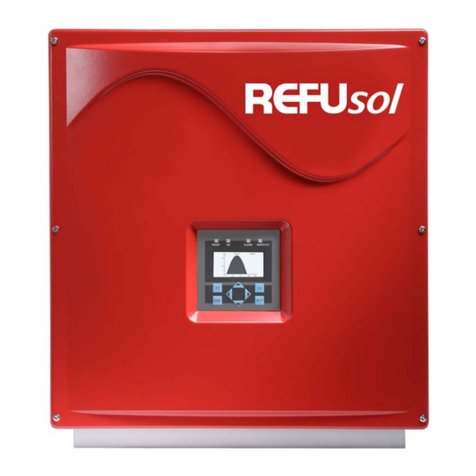
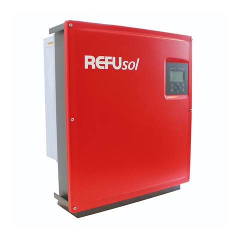
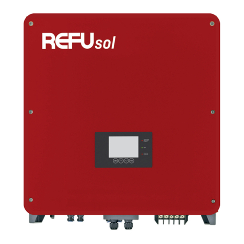
Refu sol 40K User manual

Installation and Operating Manual
REFUsol 40K / 46K-M
English
REFU Elektronik GmbH
No. 982017, ersion 022019-06
Pos: 5 /Inverter Manu als/Eingan gsteil/Rechtli che Hinweise vor Inhaltsv erzeichnis/W R @ 1\mod_ 14047366951 00_641.docx @ 6 721 @ @ 1

2 REFUsol 40K / 46K-M REFU Elektronik GmbH
Copyright
© REFU Elektronik GmbH. All rights reserved.
This manual and the information included therein are the property of REFU Elektronik GmbH.
No part of this manual is to be reproduced or copied without the express written permission of REFU
Elektronik GmbH. Any unauthorized use of this manual is strictly forbidden.
Changes may be made to specifications, descriptions and delivery information.
Publisher
REFU Elektronik GmbH, Marktstraße 185, D-72793 Pfullingen
Trademarks
REFUsol is a registered trademark.
All other trademarks or registered trademarks are the property of their respective owners.
Feedback from Customers
If you have any questions or comments regarding this manual, please contact: [email protected].
Disclaimer and Limitation of Liability
REFU Elektronik GmbH assumes no liability in the event of damage as a consequence of the failure to
observe the warning instructions in these operating instructions or of improper usage.
The operating, maintenance and safety instructions are to be read carefully prior to installation and
commissioning.
The installation, commissioning and safety-related check must be undertaken by a qualified electrician.
Error-free and safe operation of the device requires proper and professional transport, storage, assembly,
and installation, as well as careful operation and maintenance.
Only accessories and spare parts approved by the manufacturer are permitted.
Technical modifications to the device are not permitted.
Adherence to the safety regulations and provisions of the country in which the inverter will be used are to be
observed.
For European countries, the valid EU guidelines are to be observed when using the inverter.
The environmental conditions, technical calculation data and connection conditions of the grid operator
given in the product documentation must be upheld.
The technical data, calculation, connection and installation conditions are to be derived from the product
documentation and must be observed under all circumstances.
No liability is assumed for damages in connection with force majeure and disaster situations.
=== Ende der List e für Textmar ke Inhalt1 ===
Pos: 7 /gemeinsame Dokumente/ Table of C ontents @ 2\mo d_14551094 17638_641.d ocx @ 17984 @ @ 1

REFU Elektronik GmbH REFUsol 40K / 46K-M 3
Table of Contents
Copyright ............................................................................................................................................................... 2
Publisher ............................................................................................................................................................... 2
Trademarks ........................................................................................................................................................... 2
Feedback from Customers ................................................................................................................................... 2
Disclaimer and Limitation of Liability .................................................................................................................. 2
1
About this Installation and Operating Manual 6
1.1
Symbols and Markup ............................................................................................................................... 6
1.2
Warning Notices ....................................................................................................................................... 7
1.2.1
Layout of a Warning Notice ................................................................................................................. 7
1.2.2
Categories of Warning Notices ........................................................................................................... 7
1.3
Information ............................................................................................................................................... 7
2
Safety Information 8
2.1
Designated Use ........................................................................................................................................ 8
2.2
Qualification of Personnel ....................................................................................................................... 8
2.3
Dangers Arising from Misuse ................................................................................................................. 9
2.4
Protection against Contact with Electrical Parts ................................................................................. 10
2.5
Protection against Magnetic and Electromagnetic Fields during Operation and Assembly ............. 10
2.6
Protection against Contact with Hot Parts ........................................................................................... 11
2.7
Protection during Handling and Assembly ........................................................................................... 11
2.8
Please Note Before Starting Up ............................................................................................................ 12
2.9
Additional Symbols and Warning Notices on the Inverter ................................................................... 13
3
Description of Device 14
3.1
Operating Mode ...................................................................................................................................... 14
3.2
Infastructure Requirements.................................................................................................................. 14
3.3
Features of REFUsol 40K / 46K-M ...................................................................................................... 15
3.4
External Dimensions ............................................................................................................................. 16
3.5
Block Diagram ....................................................................................................................................... 17
3.6
Control Panel ......................................................................................................................................... 17
3.7
Internal Data Logger.............................................................................................................................. 18
4
Installation 19
4.1
Assembly Site Requirements ................................................................................................................ 19
4.2
Transport ................................................................................................................................................ 20
4.3
Storage ................................................................................................................................................... 20
4.4
Check delivery ........................................................................................................................................ 21
4.5
Unpacking the Device ............................................................................................................................ 21
4.6
Installation ............................................................................................................................................. 23
4.7
Device Connectors ................................................................................................................................. 25
4.8
Grounding ............................................................................................................................................... 26
4.9
Residual Current Protection ................................................................................................................. 26
4.10
AC Grid Connection ................................................................................................................................ 26
4.11
Grid Line Impedance .............................................................................................................................. 27

4 REFUsol 40K / 46K-M REFU Elektronik GmbH
4.12 DC Connection of the Solar Generator ................................................................................................. 28
4.13 Phoenix T-LOX Knee Lever Connection ................................................................................................ 30
4.14 Interface Port RS485 ............................................................................................................................. 31
4.15 Ethernet Interface Connection .............................................................................................................. 32
5 Commissioning 33
5.1 Switching on the Device at Initial Start-up ........................................................................................... 33
5.2 Switching on the Device after Replacement ........................................................................................ 34
5.3 Disconnecting Device Power ................................................................................................................. 35
5.4 Setting the Country Code and the Menu Language ............................................................................. 35
5.4.1 Set Country Code/Grid Guideline ...................................................................................................... 36
5.4.2 Accepting the Country Code .............................................................................................................. 36
5.5 Device Start ............................................................................................................................................ 37
5.6 Control Panel ......................................................................................................................................... 38
5.7 Basic Screen .......................................................................................................................................... 38
5.8 Graphical Display ................................................................................................................................... 39
5.9 Energy Yield Data Display ...................................................................................................................... 39
5.10 Standardized Energy Yield Data Display ............................................................................................... 40
5.10.1 Input of Standardized Data ........................................................................................................... 40
5.11 Menu Structure ...................................................................................................................................... 41
6 Configuration 42
6.1 Changing the Menu Language .............................................................................................................. 42
6.2 Limitation of the Power Output ............................................................................................................. 42
6.3 Monitoring with REFUlog ...................................................................................................................... 43
6.4 REFUset – PC Configuration Tool ......................................................................................................... 43
6.5 Communication via Ethernet ................................................................................................................. 44
6.5.1 Automatic Setting via DHCP .............................................................................................................. 44
6.5.2 Manual Setting ................................................................................................................................... 44
6.6 Communication via RS485 ..................................................................................................................... 45
6.7 Portal Monitoring ................................................................................................................................... 45
6.8 Sending Config ....................................................................................................................................... 46
6.9 Portal Test Function .............................................................................................................................. 46
7 Troubleshooting 47
7.1 Self-Test – Error Message .................................................................................................................... 47
7.2 Transient Failure ................................................................................................................................... 47
7.3 Faults ...................................................................................................................................................... 47
7.4 Fault Acknowledgement ........................................................................................................................ 47
7.5 List of Error Messages .......................................................................................................................... 48
8 Options 53
8.1 Irradiation and Temperature Sensor .................................................................................................... 53
8.1.1 Inverter Sensor Interface .................................................................................................................. 53
8.1.2 Sensor Type Si-13TC-T-K Cable ....................................................................................................... 53
8.1.3 Assembling of the Sensor Plug ......................................................................................................... 54

REFU Elektronik GmbH REFUsol 40K / 46K-M 5
8.1.4
Connection of the Sensor at the Solar Inverter ............................................................................... 54
8.1.5
Configuration ..................................................................................................................................... 55
8.2
External Turn Off Signal ........................................................................................................................ 56
8.2.1
Overview ............................................................................................................................................. 56
8.2.2
Function .............................................................................................................................................. 56
8.2.3
Configurations.................................................................................................................................... 57
8.2.4
Configuration ..................................................................................................................................... 58
9
Maintenance 59
9.1
Maintain the Inverter ............................................................................................................................. 59
10
Decommissioning 60
10.1
Remove Inverter ..................................................................................................................................... 60
10.2
Package Inverter .................................................................................................................................... 60
10.3
Disposal .................................................................................................................................................. 60
11
Technical data 61
11.1
Inverter ................................................................................................................................................... 61
11.2
Temperature-Derating .......................................................................................................................... 63
11.2.1
Temperature-Derating REFUsol 40K ........................................................................................... 63
11.2.2
Temperature-Derating REFUsol 46K-M .................................................................................... 63
12
Certificates 64
13
Contact 65
Pos: 8 /Inverter Manu als/Zu dieser Bedienun gsanleitung/WR @ 1\mod _1405332752 576_641.docx @ 7341 @ 122 332 @ 1

6 REFUsol 40K / 46K-M REFU Elektronik GmbH
1About this Installation and Operating Manual
These operating instructions form part of the product.
Read the Installation and Operating Manual carefully before installing and using the product.
Keep the operating instructions readily available with the device for the entire service life of the
product.
Provide all future users of the device access to the operating instructions.
1.1 Symbols and Markup
Prerequisite
One-step instruction
1. Multiple-step instruction
•
Bulleted list
Highlighting Highlighting within a text
Result

REFU Elektronik GmbH REFUsol 40K / 46K-M 7
1.2 Warning Notices
1.2.1 Layout of a Warning Notice
SIGNALWORD / WARNING INSTRUCTIONS CATEGORY
Type and source of danger
Consequences if the warning is not observed
Required action to avoid the risk
1.2.2 Categories of Warning Notices
DANGER
Leads directly to death or serious personal injury if ignored.
Follow the warnings to avoid death or serious injury!
WARNING
May result in death or serious personal injury if ignored.
Follow the warnings to avoid serious injuries!
CAUTION
May cause minor personal injury if ignored.
Follow the warnings to avoid injury!
NOTICE
Can lead to property damage if ignored.
Follow the warnings to avoid damage or destruction of the product!
This symbol represent important notes concerning potential harm to people, this
unit, or associated equipment.
1.3 Information
Pos: 9 /Inverter Manu als/Sicher heitshinweise/E inleitun g/Sicherheitshinw eise @ 1\mo d_140534485 6819_641.d ocx @ 7351 @ 1 @ 1
Note:
A notice describes information which is important for the optimum and cost-
effective operation of the equipment.

8 REFUsol 40K / 46K-M REFU Elektronik GmbH
2Safety Information
Pos: 10 /Inverter M anuals/Sic herheitshinweise/ Bestimmun gsgemäße erwen dung/840 842 @ 1\mod_140 4812009063_ 641.docx @ 6 913 @ 2 @ 1
2.1 Designated Use
The REFUsol 40K / 46K-M inverter, also referred to in these operating instructions as the inverter, is a
solar inverter, which transforms the direct current generated by the P generator (photovoltaic modules)
into alternating current and feeds this into the power supply network.
The 40K is connected as a transformerless inverter directly to the low voltage supply network.
The connection of the 46K-M is connected via an isolating transformer to the medium-voltage supply
network.
The inverter has been constructed according to the current state of technology and in line with the rules of
technical safety.
Both inverters meet the requirements of degree of protection IP65 and can be used indoors and outdoors.
An agreement of the network operator for connection and operation of the inverter for low voltage network
or medium voltage network must be present.
The technical design of the network connection, the required additional electrical equipment and to the
applicable connection and installation conditions should be clarified in this regard in advance.
Any other use is not considered to be a designated use. The manufacturer accepts no liability for any damage
resulting from this.
Pos: 12 /Inverter M anuals/Sic herheitshinweise/ Qualifikation des Person als/WR @ 1\m od_14047412 89759_641.d ocx @ 6754 @ 2 @ 1
2.2 Qualification of Personnel
Target group for these instructions are professionals who can assess the assigned tasks due to their
professional training, knowledge and experience as well as knowledge of the relevant provisions and
recognize possible dangers.
Electrical work must only be carried out by qualified electricians.
Only suitably trained and qualified personnel are allowed to work on this inverter. Personnel are regarded as
being qualified if they are sufficiently familiar with the assembly, installation, and operation of the product as
well as with all warnings and safety measures set out in these operating instructions.
Pos: 13 /Inverter M anuals/Sic herheitshinweise/ Gefahren du rch falsc hen Gebrauch/ 840 842 @ 1\ mod_1404825 753362_641. docx @ 6927 @ 2 @ 1

REFU Elektronik GmbH REFUsol 40K / 46K-M 9
2.3 Dangers Arising from Misuse
DANGER
Danger to life from electric shock
Device may only be installed and serviced by qualified specialist technical
personnel.
Only class A modules according to IEC 61730 must be used.
The P generator must be free of earth potential.
The P generator must be designed in accordance with the technical data of
the inverter.
Every power supply line must be equipped with an appropriate AC-
disconnecting device.
A consumer must never be switched betw
een an inverter and line protection
switch.
Access to the shutdown mechanism must always be free.
Installation and commissioning must be carried out properly.
DANGER
Danger to life from electric shock
After the device has been switched off, the interior may still contain life-
threatening voltage
Do not open inverter.
Discharge time is at least 15 minutes.
DANGER
Danger to life from high discharge current
It is essential to ensure an earthing connection has been established prior to
connection to the supply current circuit.
Pos: 14 /Inverter M anuals/Sic herheitshinweise/Sc hutz v or Berühren e lektrischer T eile/WR @ 1\m od_14047416 02369_641. docx @ 6764 @ 2 @ 1

10 REFUsol 40K / 46K-M REFU Elektronik GmbH
2.4 Protection against Contact with Electrical Parts
DANGER
Danger to life, danger of injury due to high electrical voltage
Installation of the inverter must only be carried out by trained
specialist
personnel. In addition, the installer must be accredited by the
responsible
utility company.
General assembly and safety stipulations relating to working
on high current
facilities must be followed.
Before switching on, a check must be made to ensure that the plugs are firmly
in place (locked).
Before plugging or unplugging the DC plug, always disconnect the connection
to the P generator.
The feeder must be isolated and secured against being switched on again
before working at the AC grid.
Pos: 15 /Inverter M anuals/Sic herheitshinweise/Sc hutz v or elektromagn etischen Fe ldern/WR @ 1\m od_1411395 001262_641. docx @ 7967 @ 2 @ 1
2.5 Protection against Magnetic and Electromagnetic Fields during Operation and
Assembly
Magnetic and electromagnetic fields found in the immediate vicinity of live conductors can pose a serious
risk to persons with cardiac pacemakers, metallic implants and hearing aids.
DANGER
Danger to health for persons with pace-makers, metallic implants, and hearing
aids in direct proximity to electrical equipment
Persons with cardiac pacemakers and metallic implants may not enter areas
in which electrical devices and parts are being assembled, operated or
commissioned.
Should people wearing cardiac pacemakers need to enter such
areas, the
decision as to whether this is permitted is to be made by a doctor beforehand.
Immunity from interference of cardiac pacemakers that have already been
implanted or will be in future varies greatly, meaning that there are no
generally applicable rules in this respect.
Persons with metal implants or metal splinters, as well as those with hearing
aids, must ask a doctor before entering such areas, as impairments to health
are to be expected.
Pos: 16 /Inverter M anuals/Sic herheitshinweise/Sc hutz v or Berühren h eißer Teile/WR @ 1\mod_14 04741731923_ 641.docx @ 6 769 @ 2 @ 1

REFU Elektronik GmbH REFUsol 40K / 46K-M 11
2.6 Protection against Contact with Hot Parts
CAUTION
Danger of burns caused by hot surfaces on housings
At an ambient temperature of 45 °C, the upper part of the housing as well as the
refrigeration unit can reach a surface temperature of more than 75 °C.
Do not touch the housing surface near to heat sources.
Allow the device to cool down for 15 minutes before touc
hing the surface of
the device.
Pos: 17 /Inverter M anuals/Sic herheitshinweise/Sc hutz be i Handhabun g und Montag e/WR @ 1\mo d_14047418 79396_641.docx @ 6774 @ 2 @ 1
2.7 Protection during Handling and Assembly
WARNING
Danger of injury during improper handling caused by crushing, shearing,
cutting, striking, and lifting
The weight of the inverter is 75.6 kg!
Follow the general setup and safety regulations for handling and assembly.
Use suitable assembly and transportation equipment.
Avoid trap and crush injuries by taking suitable precautions.
Only use suitable tools. Use special tools where this is prescribed.
Use lifting equipment and tools in a technically correct manner.
If necessary, use suitable protective equipment (for example, goggles, safety
footwear, protective gloves).
Do not stand under hanging loads.
Remove any liquids onto the floor immediately to avoid the danger of slipping.

12 REFUsol 40K / 46K-M REFU Elektronik GmbH
2.8 Please Note Before Starting Up
•In the event of installation in France, the device must be furnished with the warning sticker laid
down by UTE C 15-712-1. The warning stickers are included in delivery.
•Problem-free and safe operation of the inverter is conditional upon due and specialized
transportation, storage, assembly and installation as well as careful operation and maintenance.
•Only use accessories and spare parts approved by the manufacturer.
•Adherence must be ensured to the prescriptions and stipulations regarding safety of the country in
which the inverter is to be used.
•The ambient conditions stated in the product documentation must be observed.
•In the planning and installation of the P system, the technical design data, installation and safety of
the P module manufacturer must be observed.
•Starting up is prohibited until the entire system meets the national regulations and safety rules
regarding use.
•Operation is only permitted with adherence to the national EMC prescriptions for the present use
case.
•The manufacturer of the equipment or machine is responsible for ensuring compliance with the
thresholds required by the respective national regulations.
•For European countries, the EU Directive 2014/30/EU (EMC Directive) and 2014/35/EU (L D
Directive) is to be observed when using the inverter.
•The technical data, connection and installation conditions are to be taken from the product
documentation and must be observed under all circumstances.
•During installation, operation, maintenance and repair the following standards must be observed:
oEN 50110-1: Operation of electrical installations - Part 1: General requirements
oEN 50110-2: Operation of electrical installations - Part 2: National annexes
oIEC 60364-1: Low-voltage electrical installations - Part 1: Fundamental principles,
assessment of general characteristics, definitions
oIEC 60364-7-712: Low-voltage electrical installations - Part 7-712: Requirements for special
installations or locations - Photovoltaic (P ) power systems
oIEC 61730-1: Photovoltaic (P ) module safety qualification. Part 1: Requirements for
construction
oIEC 62109-1: Safety of power converters for use in photovoltaic power systems - Part 1:
General requirements
oIEC 62109-2: Safety of power converters for use in photovoltaic power systems - Part 2:
Particular requirements for inverters
oIEC 82/749/CD: Grid connected P systems - Minimum requirements for system
documentation, commissioning tests and inspection
oIEC 62305-1: Protection against lightning - Part 1: General principles
oIEC 61439-1: Low-voltage switchgear and controlgear assemblies - Part 1: General rules
oIEC 61643-11: Low-voltage surge protective devices - Part 11: Surge protective devices
connected to low-voltage power systems - Requirements and test methods

REFU Elektronik GmbH REFUsol 40K / 46K-M 13
2.9 Additional Symbols and Warning Notices on the Inverter
Indication of P system
General warning sign
Warning of electrical voltage
Hot surface! The housing can get hot during use.
This symbol advises that the user handbook must be read
before the device is used.
The inverter must be earthed before use.
Before beginning of work switch unit free of voltage.
Warning of electrical voltage on DC and AC side.
All solar strings on the DC side are at voltage.
Discharging time of the device longer than 15 minutes.

14 REFUsol 40K / 46K-M REFU Elektronik GmbH
3Description of Device
Pos: 21 /Inverter M anuals/Ger ätebeschreibun g/Funktions prinzip/842 @ 3\mod_1478 694165628_6 41.docx @ 25 306 @ 2 @ 1
3.1 Operating Mode
The REFUsol 40K / 46K-M transforms the direct current generated by photovoltaic (P ) modules into
alternating current and feeds this into the public grid.
1
3
2
4
5 6
7
2
Figure 1: How it works: a grid-connected P system with photovoltaic inverter
1 P modules
2 Solar string combiner box
3 REFUsol 40K / 46K-M photovoltaic inverter
4 Fuse switch disconnector or circuit breaker
5 Grid Protection
6 Isolation transformer is required for medium-voltage network
7 Low or medium-voltage AC grid
Pos: 22 /Inverter M anuals/Ger ätebeschreibun g/ oraussetzungen Infrastruktur/ 842 @ 1\m od_14115673171 28_641. docx @ 8098 @ 2 @ 1
3.2 Infastructure Requirements
Additional required
equipment
40K at the low voltage
network
40K/46K-M at the medium voltage
network
DC load break switch integrated* integrated*
AC load break switch necessary necessary
Central grid protection
device ( DE-AR-N 4105)
necessary necessary
L -/M -Transformer not necessary necessary
*local regulation might require an additional DC switch at the external DC combiner box.
The following points are to be considered when planning the infrastructure:

REFU Elektronik GmbH REFUsol 40K / 46K-M 15
•The 40K can feed into the low-voltage grid and the medium-voltage grid.
•The 46K-M can only feed into the medium-voltage grid.
•The 5-wire power supply line must be equipped with an appropriate AC disconnecting device.
•The 40K/46K-M is not equipped with internal potential isolation.
•If the 40K/46K-M is connected with the medium-voltage-grid, it must be operated with electrically
isolating transformers.
•No other equipment may be connected between the transformer and inverters.
The following standards and technical regulations are also to be observed:
IEC 60364-4-41 Protection: Protection against electric shock
IEC 60364-4-43 Protection for safety - Protection against overcurrent
IEC 60364-5-52 Selection and erection of electrical equipment - wiring systems
BDEW Technical Guidelines
DN Technical Guidelines
For the REFUsol 40K / 46K-M an isolating transformer with the following specifications is required:
Specification of medium voltage transformers 40K 46K-M
Rated power 40 k A 46 k A
Rated voltage OS Depends on grid connection point
Rated voltage US 3 x 400 PE + N 3 x 460 PE + N
Frequency 50/60 Hz 50/60 Hz
Short-circuit voltage u
k
Depends on grid connection point
Switching group Dyn5 or Dyn11 Dyn5 or Dyn11
Pos: 23 /Inverter M anuals/Ger ätebeschreibun g/Merkma le/840 842 843 844 @ 1\mod _1411395847 660_641.docx @ 7977 @ 2 @ 1
3.3 Features of REFUsol 40K / 46K-M
The REFUsol 40K / 46K-M inverter is a transformer-less, three-phase solar inverter, which has a
particularly high efficiency at any operating point.
Heat is dissipated only by convection. The internal temperature control prevents the device from exceeding
the permissible ambient temperature.
The inverter is designed such that the device does not have to be opened for assembly and connection work.
The inverter provides communication interfaces for RS485 and Ethernet. The communication protocol is
Modbus and Sunspec compliant.
An illuminated graphical display shows the development of the feed-in power and other operating data in a
clearly arranged manner. An 8-key control panel below the display also provides excellent control and
navigation convenience. Based on its design in protection class IP 65, the inverter can be installed at almost
any outside location. The inverter has extensive safety and security features. For details, refer to Technical
Data.

16 REFUsol 40K / 46K-M REFU Elektronik GmbH
3.4 External Dimensions
Fig. 2: External dimensions

REFU Elektronik GmbH REFUsol 40K / 46K-M 17
3.5 Block Diagram
Fig. 3: Block diagram
1) DC switch
2) DC overvoltage protection
3) DC EMC filter
4) DC current measurement
5) Isolation monitoring
6) DC voltage measurement
7) AC current measurement
8) AC grid relays (redundant)
9) AC voltage and frequency measurement
10) AC EMC filter
11) AC overvoltage protection
12) Fault current monitoring, Type 2
13) Protective earth connection
14) Interfaces (Ethernet, RS485, Sensors, remote stop)
Pos: 28 /Inverter M anuals/Ger ätebeschreibun g/Bedienfe ld/WR @ 1\mo d_1410957749 856_641.docx @ 7880 @ 2 @ 1
3.6 Control Panel
The graphical user interface which is integrated on the front of the device and comprises 128 x 64 pixels can
be used to display the operation data, such as the feed-in power or yield. The parameters required are
selected and entered on the 8-key control panel. The control panel is illuminated when a key is pressed and
turns dark automatically.

18 REFUsol 40K / 46K-M REFU Elektronik GmbH
Fig. 4: Control panel
Pos: 29 /Inverter M anuals/Ger ätebeschreibun g/Interne r Datenlogger/W R @ 1\mod_ 14109578453 75_641.docx @ 7 886 @ 2 @ 1
3.7 Internal Data Logger
The inverter features an internal data logger that allows measured values to be simultaneously recorded in
the form of parameters. If the storage capacity is full, the oldest data is overwritten. With the default setting
on delivery, the data logger logs 16 measuring channels, which can be displayed an analyzed by REFUlog.
Recording cycle Storage time
1 minute 2.5 years
2 minutes 5 years
5 minutes 12.5 years
10 minutes 25 years
Pos: 30 /Inverter M anuals/Insta llation/Übe rschrift/Installati on @ 1\m od_1406617845 321_641. docx @ 7502 @ 1 @ 1
Status
LEDs

REFU Elektronik GmbH REFUsol 40K / 46K-M 19
4Installation
Pos: 31 /Inverter M anuals/Insta llation/Anf orderungen an M ontageort/ 842 843 844 @ 3\ mod_1478 694801881_6 41.docx @ 25 356 @ 2 @ 1
4.1 Assembly Site Requirements
DANGER
Danger to life due to explosion
Do not install inverter in areas with risk of explosion.
DANGER
Danger to life due to fire
Do not install inverter on flammable materials. Uphold fire protection class
according to NFPA regulation.
Do not install inverter in areas where easily flammable materials are stored.
Under no circumstances are the cooling fins of the heat sink to be covered.
WARNING
Danger of accident
When installing and servicing, unrestricted and safe access to the devices
must be ensured.
The following requirements of the installation site must be upheld:
•Only vertical installation is permitted as otherwise the cooling of the device cannot be guaranteed
(convection cooling).
•Prolonged exposure to direct sunlight can cause an internal temperature rise, leading to power
derating of the device. It is recommended to install a sunshade to mitigate the thermal impact of
irradiation.
•A fixed wall or a metal construction is necessary for installation. The weight of an inverter amounts
up to 75.6 kg. Relevant construction regulations must be observed.
•The device is to be mounted at an appropriate distance from combustible materials.
•Installation in non-ventilated ended cabinets and enclosures is not allowed because the unit in
operation emits heat.
•To allow for the heat dissipation required, keep the following minimum distances from the ceiling
and wall as well as from neighbouring devices:

20 REFUsol 40K / 46K-M REFU Elektronik GmbH
150 mm
(5.91″)
150 mm
(5.91″)
500 mm (19.69″)500 mm (19.69″)
Fig. 5: Minimum distances
The device is best operated if the display is at eye level.
Pos: 32 /Inverter M anuals/Insta llation/Transp ort/WR @ 1\ mod_140480 4888165_641. docx @ 6809 @ 2 @ 1
4.2 Transport
The devices must be transported under clean and dry conditions, if possible in their original packaging. The
transport temperature must be between -25 – +60 °C. Permissible variations in temperature may not exceed
20 °C (68 °F) per hour.
Pos: 33 /Inverter M anuals/Insta llation/Lagerun g/WR @ 1\ mod_140480 5008393_641. docx @ 6815 @ 2 @ 1
4.3 Storage
The devices must be stored in clean and dry premises, if possible in their original packaging. The storage
temperature must be in the range of -25 – +60 °C. Permissible variations in temperature may not exceed
20 °C (68 °F) per hour.
Other manuals for 40K
1
This manual suits for next models
1
Table of contents
Other Refu sol Inverter manuals
Popular Inverter manuals by other brands

Trace Engineering
Trace Engineering LEGEND I Owner's/operator's manual

Goodwe
Goodwe GW9.9KAU-DT Quick installation guide

Velleman
Velleman PSI300SB user manual

MidNite Solar
MidNite Solar Rosie MNROSIE7048RE owner's manual

Samlexpower
Samlexpower PST-200S-12A owner's manual

Batterytech
Batterytech E-Gen 400 user manual

EINHELL NEW GENERATION
EINHELL NEW GENERATION STE 5000D operating instructions

MULTIQUIP
MULTIQUIP TLG8SSK4F Operation and parts manual

Epever
Epever UP2000-HM6021 user manual

Kemot
Kemot PROsolar-5000 owner's manual

BONFIGLIOLI
BONFIGLIOLI DGM MPM Technical manual

CMS
CMS 4000 Installation and operation manual