Unitor UWW-161 TP User manual

Revision date: 23 09 2014 Page 1 of 32
Instruction manual
& spare parts list
Unitor Welding Inverter
UWW-161 TP
Multi Process MIG-MAG-MMA-TIG
TP (total protection) version, from serial number 111194

Revision date: 23 09 2014 Page 2 of 32
DECLARATION OF CONFORMITY
₪₪₪₪₪₪₪₪₪₪₪₪₪₪₪₪₪₪₪₪₪₪₪₪₪₪₪₪₪₪₪₪₪₪₪₪₪₪₪₪₪₪₪₪₪₪₪₪₪₪
We hereby state that the machine type
UWW-161TP
TP (Total Protection)
version
s.n.: 111194 and higher
₪₪₪₪₪₪₪₪₪₪₪₪₪₪₪₪₪₪₪₪₪₪₪₪₪₪₪₪₪₪₪₪₪₪₪₪₪₪₪₪₪₪₪₪₪₪₪₪₪₪
is in compliance with the directives
2004/108/CE
2006/95/CE
₪₪₪₪₪₪₪₪₪₪₪₪₪₪₪₪₪₪₪₪₪₪₪₪₪₪₪₪₪₪₪₪₪₪₪₪₪₪₪₪₪₪₪₪₪₪₪₪₪₪
and that the following standards apply
EN 60974-1
EN 60974-5
EN 60974-10
₪₪₪₪₪₪₪₪₪₪₪₪₪₪₪₪₪₪₪₪₪₪₪₪₪₪₪₪₪₪₪₪₪₪₪₪₪₪₪₪₪₪₪₪₪₪₪₪₪₪
Belvedere, Maggio 2004
Amm. Giorgio TONIOLO
WECO srl
Via S. Antonio, 22 - BELVEDERE
36050 TEZZE SUL BRENTA (VICENZA) ITALY
Tel. +39 0424 561943 - Fax +39 0424 561944
P. IVA 02783960244 - C.F. 02710490281
Reg. Impr. VI n° 52214 - R.E.A. N° 274736
Capitale sociale i.v. € 52.000,00
UWW-161TP s.n.: 111194 and higher is also in compliance with the
RoHS directive 2002/95 CE

Revision date: 23 09 2014 Page 3 of 32
CONTENTS
1. GENERAL DESCRIPTION
2. IDENTIFY COMPONENTS
3. TECHNICAL DATA
4. INSTALLATION
5. FRONT PANEL
6. SPOOL COMPARTMENT
7. WIRE LOADING
8. OPERATING INSTRUCTIONS
9. WIRE WELDING CONSUMABLE SPARES
10. WIRE WELDING ACCESSORIES
11. SHIELDING GAS ACCESSORIES
12. TIG ACCESSORIES
13. MAINTENANCE
14. TROUBLESHOOTING
15. WIRING DIAGRAM
16. COMPONENTS AND SPARES
17. SAFETY INSTRUCTIONS
18. YOUR OWN NOTES
DO NOT INSTALL, OPERATE OR REPAIR THIS EQUIPMENT WITHOUT READING
THIS MANUAL AND THE SAFETY PRECAUTIONS CONTAINED THROUGHOUT

Revision date: 23 09 2014 Page 4 of 32
1. GENERAL DESCRIPTION
UWW-161 TP is a compact and portable Single Phase Inverter Power Source for professional MIG-MAG,
TIG and MMA welding.
It connects to a standard 230V one phase socket, preferably with slow fuses to allow full power.
The TP (total protection) version is protected against too high input voltage and will close down completely to
prevent damage if input voltage exceeds 285V. A led on the rear panel will be lit to indicate that the
protection is on. When the input voltage is reduced welding power will automatically be restored.
The automatic Voltage Reducing Function provides operator safety by reducing “touchable” voltage for the
operator to max. 10V between electrode holder and work-piece.
The automatic Amperage Draw Protection will cut the current to prevent damage to the machine, and sound
an alarm tone to warn the operator if welding with the set wire welding parameters exceeds the capacity of
the unit.
UWW-161 TP is easy to transport, only 12kg weight and it is specifically designed for light fabrication,
maintenance and repair work on board.
It offers excellent MIG-brazing characteristics using CuSi3 and CuSi6 type wires.
Polarity change for Euro-connector allows welding with self shielded wires.
User-friendly control panel allows precise parameters settings using only two knobs.
Selection between a softer and crisper arc allows optimal arc for various wires.
Built-in wind tunnel cooling protects electronic devices from dust and saltiness, improving the UWI-161 MP
arc welder’s life cycle.
• Light weight and reliable
• Up to 3,25mm electrodes in MMA
• Lift arc TIG DC ignition reduces Tungsten inclusions without generating the radio interference that High
frequency arc start may cause.
• Excellent MIG/MAG welding properties.
• Polarity selection for self-shielded wire welding.

Revision date: 23 09 2014 Page 5 of 32
2 IDENTIFY COMPONENTS
UWW-161 TP complete, product number 193-161161 is delivered with
1
Primary cable, 2.5m with plug (fitted on machine)
1 piece
2
Gas hose socket with nut and hose clamp
Product number 161165
1 set
3
Drive roll V groove, 0.6-0.8mm (fitted in machine)
Product number 160003
1 piece
4
Outgoing wire guide tube for mounting in the wire drive unit
1 piece
5
MIG/MAG torch M-161 with 3m cable and euroconnector
Product number 161163
1 piece
6
Steel liner (fitted in torch cable)
Product number 613746
1 piece
7
Contact tip 0.8mm, (fitted in torch)
Product number 711994
1 piece
8
Return clamp with 3m cable and connector
Product number 633164
1 set
9
Electrode holder with 3m cable and connector
Product number 627877
1 set
10
Carrying strap for mounting on the machine
1 piece
11
Instruction Manual
1 piece
1
9
10
11
8
5
6
7
4
3
2

Revision date: 23 09 2014 Page 6 of 32
3 TECHNICAL DATA
Type of welding machine
Processes
Safety Marking
Suitable for use in areas with increased electric shock hazard
The unique serial number for the
machine will be printed here.
Always give serial number when
ordering spares or in other
communication with WSS
concerning your machine.
One-phase static transformer rectifier
frequency converter, DC output.
MMA (Stick
electrode /
SMAW)
TIG
(GTAW)
MIG/MAG (Metal Inert Gas/Metal Active Gas)
GMAW (Gas Metal Arc Welding)
FCAW (Flux Cored Arc Welding)
TP

Revision date: 23 09 2014 Page 7 of 32
X: Duty cycle
Duty Cycle is percentage of 10 minutes that unit can weld at rated load without overheating.
It refers to a 40°C environmental temperature. If unit overheats a thermal switch stops the output, the
warning light for over-temperature is lit and the cooling fan continues to run. Wait fifteen minutes for unit to
cool. Reduce amperage or duty cycle before starting to weld.
I2= Welding current.
Range 5 –140 / 160A
U0= No-load voltage
Also called open circuit voltage, is the voltage (excluded any stabilization voltage or arc ignition) found
between the output outlets when the welding machine is not welding. This is the voltage a welder can be
exposed to between electrode holder and work piece.
U2= Arc voltage
Voltage present between the output outlets when welding is being carried out, in relation to a particular set
current. The relation, for the various welding modes is the following:
MMA→U2=20+0,04*I2,TIG →U2=10+0,04*I2,MIG/MAG→U2=14+0,05*I2
Primary connection
U1= Effective input voltage 230V
I1max = Maximum value of input current at the corresponding duty cycle.
I1eff = Effective value of input current at the corresponding duty cycle.
Maximum input power is 5,4 kVA. Power factor 0,79. Duty Cycle 35%
Cooling
COOLING AF= Forced air cooling (with a fan).
Protection class
IP23S= Ingress Protection class. Protection degree of the casing according to EN 60529
2: Protection against object not greater than 80mm in length and 12mm in diameter
3: Protection from sprayed water at an angle of 60º from vertical
S: Valid when switched off. If welding in heavy rain the cooling air can drag in moisture.
Thermal insulation class
I.CL.H= Thermal class of the insulating materials and insulation systems resistant up to 180°C.
Standards
EN 60974-10 European Norm for electromagnetic compatibility.
EN 60974-1/5 European Norm for arc welding appliance: Current sources for welding.
Mark stating conformity to all safety standards and other standards required for sale
within the European Union
Dimensions and weight
Height : 325mm
Length : 460mm
Width : 230mm
Weight : 12,2kg
Revision date: 23 09 2014 Page 8 of 32
4 INSTALLATION
Only qualified personnel should perform this installation.
Only personnel that have read and understood this Manual should install and operate this equipment.
The machine must only be plugged into a receptacle which is grounded per applicable electrical codes.
Note 1
The power switch is to be in the OFF position when installing work cable and torch and when connecting
power cord to input power.
Note 2
The parts behind the wire drive door are live when wire welding. Never open or leave this door open while
welding
SELECT SUITABLE LOCATION
The UWW-161TP has an IP23S rating. Locate the welder in a dry location where there is free circulation of
clean air into the back and out the front of the unit.
Ensure minimum 50cm free space from the back of the machine. If free flow of air is hindered the machine
will overheat.
A location that minimizes the amount of smoke and dirt drawn into the machine reduces the chance of dirt
accumulation that can block air passages and cause overheating.
AVOID TILTING
The machine must be placed on a secure, level surface, maximum 10º out of horizontal.
ASSEMBLY
To the back panel
1 Primary connection 230V 50/60Hz 1phase
+ protective earth. 2,5m cable 3x2,5mm²
with plug is included
2 Gas Cylinder with Argon, Argon/CO2 or
CO2 (not included with machine)
3 Gas regulator with flow adjustment (not
included with machine)
4 Gas hose (not included with the machine)
5 Hose socket with nut and hose clamp for
6mm (1/4”) hose, included with the machine
Inside the machine
6. Spool of welding wire
(not included with the machine)
7. Wire feed roll V-groove for 0,6-0,8mm wire
To the front panel
8.a MIG torch (included with the machine) to the Euro-connection
- then select polarity to the Euro-connection with the cable and Dix-connector on the front panel.
- then connect the return cable to the other polarity. MIG torch is included with the machine
8.b TIG torch (not included with the machine) to the Euro-connection
- then select –(negative) polarity to the Euro-connection with the cable and Dix-connector on the front panel.
- then connect the return cable to the + (positive) polarity
8.c Electrode holder (included with the machine) for MMA welding to the + or –socket depending on the type of
electrode to be used
8.d Return clamp (included with the machine) for all processes to the free (+ or -) socket.
On (I) OFF (0) Switch
Gas inlet
LED indicating that
protection against too high
input voltage has been
activated
Important!
To prevent overheating the machine requires at least 0,5 m
free distance at the back to allow free flow of cooling air.
8

Revision date: 23 09 2014 Page 9 of 32
POLARITY SELECTION
In the picture below the cable supplying current to the Euro-connector is connected to the machine plus-
connection. The cable to return current (ground clamp) then has to be connected to the machine minus-
connection to the right in the picture. This means the machine is set for welding with electrode plus polarity
from the Euro-connector to the right, which is the normal setting for MIG/MAG welding.
For Self-shielded wires (without shielding gas) and for TIG welding the minus polarity should normally be
selected, and the return clamp should be connected to the plus polarity.
For stick electrode welding (MMA) the cable in the picture is disconnected as shown in the drawing, and
electrode cable and return cable are connected to plus and minus according to the requirements of the
electrode that is going to be used.
+
_
Euro-connector for
TIG and MIG torch
The outgoing wire
guide tube is inserted
here, slightly bent to
prevent it from falling
out when the MIG
torch Euro-connector is
disconnected.
,

Revision date: 23 09 2014 Page 10 of 32
5 FRONT PANEL
1. Wire speed adjustment. See separate table under OPERATION for relation between wire speed and
approximate welding current. This adjustment is only active when one of the wire welding modes are
selected
2. When this LED is lit, it means that the thermal cut-out for overheating of the machine has triggered
and there is no welding current. Do not switch the machine off. The fan will be running and the
thermostat resets automatically when the machine has cooled down sufficiently. The light will darken
when the machine is live again.
When the machine is switched on, this LED is lit for five seconds, during which time there is no
welding current available.
3. Power on. When this LED is on welding current is available. In MMA (stick electrode) welding mode
the open circuit voltage of 10V is present between + and –terminals.
4. Warning light indicating live terminals
5. Welding current / voltage adjustment. The green scale A 5-140 show selected amperage for MMA
(stick electrode) welding. The white scale V 10-26 show selected voltage for MIG (wire) welding
6. Wire feed function. By pressing this knob wire will be fed through to the torch without being
electrically live.
1
2
3
4
5
8
7
6

Revision date: 23 09 2014 Page 11 of 32
7. This knob is active in the MIG/MAG mode only and allows selection between two arc types.
When the led above the knob is lit a softer welding arc for MIG brazing is obtained.
When the led is dark the normal, slightly crisper or harder arc is obtained.
8. Mode selection
2 step wire welding
•Bring the torch close to the piece you mean to weld.
•Press (step 1) and hold the torch button.
•The wire advances at closing speed until it contacts with the work-piece. The
welding arc is lit and the set wire feed speed will continue at set speed.
•Release the button (step 2) in order to start the welding completion procedure.
•The supply of gas continue for the selected post-gas time
4 step wire welding
•Bring the torch close to the piece you mean to weld.
•Press (step 1) and release (step 2) the torch button.
•The wire advances at closing speed until it contacts with the work-piece. The
welding arc is lit and the set wire feed speed will continue at set speed.
•Press (step 3) and release (step 3) the button in order to start the welding
completion procedure.
•The supply of gas continue for the selected post-gas time
MMA (stick) welding
In this mode a constant current characteristic for MMA welding is set and the
terminals are live (10V).
An automatic hot-start enables easy arc start. And an automatic arc-force maintains
a smooth and stable arc by momentarily increasing the current if bigger droplets in
the arc tends to produce short circuits.
An automatic anti-stick function will cut the power if the electrode should get stuck in
the melt-pool so that it can be removed without damage.
2 step TIG welding
•Touch the electrode to the piece you mean to weld.
•Press (step 1) and hold the torch button. Shielding gas and very small “signal”
current will start flowing.
•Lift the torch slowly, and the signal current will initialize an arc and an up-slope
function that increases the current to set value.
NOTE: The arc must be started within 3 seconds, if not the signal current will be
stopped to protect the circuit and a new start cannot be done before gas supply
has stopped.
•Release the button (step 2) in order to start the slope-down function that gradually
reduces the welding current to zero.
The supply of gas will continue for the selected post-gas time

Revision date: 23 09 2014 Page 12 of 32
6 SPOOL COMPARTMENT
Fuse for the auxiliary transformer
providing current to the wire feed
motor: 800mA 250V slow fuse.
Gas post-flows pot-meter the gas post-flow for MIG
and TIG can be adjusted from 0-3 seconds. It must
be long enough to ensure sufficient cooling of the
weld pool to avoid oxidation.
Wire feed system with drive rolls and
pressure adjustment.
Shaft for spool attachment and
Friction Brake Adjustment
The drive rolls have two grooves for two different wire sizes
V-groove 0,6-
0,8mm for solid
wires except
aluminium
GPS
GPS W 200
IALBRO W 237
ICUNI W 239
Knurled V-
groove 1,0 (0,8) -
1,2mm for flux-
cored wires
MS W 201
S 316 M-GF 221
S 309 M-GF 222
U-groove 0,8-
1,0mm for
aluminium wires
ALUMAG W 235

Revision date: 23 09 2014 Page 13 of 32
7 WIRE LOADING
Release the spring loaded pressure arm
(1) rotate the roll arm (2) up from the wire
feed drive roll (3).
Ensure that the groove size in the feeding
position on the drive roll matches the wire
type and size.
Place the wire spool in place on the wire
spool spindle (4). Make sure that the stud
(5) engages in the corresponding hole in
the wire spool
Check the Friction Brake Adjustment, a
bolt inside the spindle (6).
When properly adjusted, the brake should
provide only enough drag to prevent
overrun of the spool and excess slack in
the wire. Too much drag may result in
wire feeding problems,
Replace the cap (7).
Carefully detach the end of the wire from
the spool, cut the bent portion of wire off
and straighten the first 10cm.
Thread the wire through the ingoing guide
tube (8), over the drive roll (3), and into
the outgoing guide tube.
Close the idle roll arm (2) and latch the
spring loaded pressure arm (1) in place.
The roll pressure on the wire is adjusted
with the screw on the pressure arm. nut
above the spring. It should be sufficient to
ensure smooth feeding of the wire.
Rotate the spool counterclockwise if
required to take up extra slack in the wire.
1
S
8
3
2
5
4
6
7

Revision date: 23 09 2014 Page 14 of 32
8 OPERATING INSTRUCTIONS
1. Welding wire has been selected
2. Correct polarity to the torch / welding wire has been selected
3. Wire spool has been inserted, spool brake has been checked, wire inserted in the central connector, and
the idle roll arm has been closed.
4. Torch has been connected to the front of the machine
5. Return clamp has been properly connected to the work piece
6. Correct shielding gas (if required) has been connected to the gas inlet at the back of the machine and to
a gas cylinder with gas flow regulator, and the cylinder valve has been opened.
7. The wire compartment is closed and the machine switched on.
Next steps
8. Set the lowest wire feed speed, press the torch trigger. The gas solenoid valve will now open and allow
to adjust correct gas flow on the flow regulator.
9. Pull off the nozzle from the torch, unscrew the contact tip and straighten the gun cable assembly
10. Press wire feed knob (6) on the front panel to feed the wire out through the torch neck.
11. Replace the contact tip and nozzle.
12. Set wire speed and voltage in accordance with the wire specifications and proceed with the welding.
13. When finished, close the gas cylinder and press the trigger shortly to vent off gas pressure in hoses and
machine before switching off and unplugging.
Examples on parameter settings
Unitor Wire
Wire size
mm
Groove type
Wire
speed
m/min
Volt
and
polarity
Shielding
gas
Gas flow
GPS W 200
0,8
V
7,5
22V +
Ar/CO2
10-15 l/min
MS W 201
0,8
V-serrated
12
20V -
No gas
S 316 M-GF 221
0.9
V-serrated
11
22V +
Ar/CO2
22-25 l/min
S 309 M-GF 222
0.9
V-serrated
13
24V +
Ar/CO2
22-25 l/min
Icuni W 239
0,8
V
7,5
22V +
Ar
15-20 l/min
Ialbro W 237
0,8
V
7,5
22V +
Ar
15-20 l/min
Alumag W 235
1,0
U
12
23V +
Ar
15-20 l/min
Alumag W 235
1,0
U
7,5
22V +
Ar
15-20 l/min
CuSi3Mn*
1,0
V
7,5
22V +
Ar
15-20 l/min
CuSi3Mn*
1,0
V
5,5
18V +
Ar
15-20 l/min
*MIG brazing wire on request. Activate “soft arc” on the front panel for brazing
Torch Neck
Contact Tip
Nozzle

Revision date: 23 09 2014 Page 15 of 32
9 WIRE WELDING CONSUMABLE SPARES
Product number
Product Description
Wire size mm
mm
Application area
Cored wires
steel
Solid wires
steel
Cored wire
stainless
Solid wire
stainless
Solid wire
non-iron
Aluminum
wire
WIRE FEED DRIVE ROLLS
160003
Drive roll V-groove
0,6-0,8
o
X
o
X
X
o
160004
Drive roll U-groove
0,8-1,0
-
-
-
-
-
X
160005
Drive roll V-groove knurled
1,0-1,2
X
o
X
o
-
-
WIRE FEED LINERS
590075
Non iron liner *
0,6-1.2
X
X
X
X
X
X
613746
Steel liner**
0,6-1,2
X
X
-
-
-
-
CONTACT TIPS
711986
10 tips 0.6mm
0,6
X
X
X
X
X
**
711994
10 tips 0.8mm
0,8
X
X
X
X
X
**
712000
10 tips 1.0mm
0,9-1,0
X
X
X
X
X
**
712018
10 tips 1,0-1.2mm (max 1mm al)
1,2
X
X
X
X
X
X
GAS NOZZLES
160001
GAS NOZZLE
0,6-1,2
All wires requiring gas shielding
X = Well suited
O = May be used, but not the best solution
-= Not recommended, do not use
* = Non iron liner can be used for all welding wires, but wears down quicker than steel liners
** = Steel liner is a more wear resistant alternative for black steel welding but should be avoided for
stainless and non iron wires to avoid contamination of the weld.
10 WIRE WELDING ACCESSORIES
The Anti spatter spray prevents the spatter from the welding arc from sticking to
the metal surface adjacent to the weld. By spraying on a thin layer on each side of
where the welding is to take place, a barrier is formed preventing the molten
globules from burning on to the surface.
The spatter can easily be wiped off with a brush after welding. Time consuming
chipping and grinding is prevented. The spray is packed in an outer carton
containing 6 X 400 ml cans.
The multipurpose pliers provides means for spatter
removal from the nozzle inside, tip and outside.
It has jaws for contact tip and nozzle removal
and installation, and for cutting and pulling wire.
Multipurpose pliers for torch pcs 193-591990
Anti Spatter Spray, 6 pcs of 400 ml in a box set 193-633149

Revision date: 23 09 2014 Page 16 of 32
11 SHIELDING GAS ACCESSORIES
Regulator with flow adjustment 0-32 l/min
for Argon and Mixed gas
pcs
197 510010
Regulator with flow adjustment 0-32 l/min
for CO2 shielding gas
pcs
193 510012
Gas hose ¼” black, for shielding gas
m
176 576157
Hose clamps, one ear for ¼” hose, non-
protruding stainless, bag of 10 pcs
set
401 729442
Pinching tool for ear clamps
pcs
401 768507
Hose joint for 1/4" hose, 3/8" RH threads
pcs
176 175596
Flowcontrol meter for use at torch nozzle
pcs
197 597328
Flowcontrol needle valve for gas inlet
pcs
197 597310
Argon / CO2 mix gas is used for steel and stainless steel
Pure Argon is used for all non iron metals.
Both gases are available in 10 and 50litre cylinders.
Pure CO2 may also be used as shielding gas, but only for
black steel with maximum thickness 2mm.
A special regulator for the CO2 cylinder is then required
12 TIG ACCESSORIES
TIG-Torch T-161 with 4m cable, euro-
connector and torch mounted trigger
pcs
197 160010
TIG accessories kit including short back
cap. spare heat-shield, collets, collet
bodies, nozzles and electrodes
pcs
197 607810
Hose joint for 1/4" hose, 3/8" RH threads
pcs
176 175596
Flowcontrol meter for use at torch nozzle
pcs
197 597328
Flowcontrol needle valve for gas inlet
pcs
197 597310

Revision date: 23 09 2014 Page 17 of 32
13 MAINTENANCE
POWER SOURCE COMPARTMENT
In extremely dusty locations, dirt may clog the air passages causing the welder to run hot. Blow dirt out of the
welder with low pressure dry, oil-free air at regular intervals to eliminate excessive dirt and dust build-up on
interval parts.
WIRE FEED COMPARTMENT
1. When necessary, vacuum accumulated dirt from gearbox and wire feed section.
2. Occasionally inspect the incoming guide tube and clean inside diameter if necessary.
3. Motor and gearbox have lifetime lubrication and require no maintenance.
FAN MOTOR AND WIRE REEL SPINDLE
Requires no maintenance. Do not lubricate shaft.
TORCH
1. Check wire feed liner for damage or wear at regular intervals. This is especially important for the
non iron liner which may wear quickly if used for extensive shelf-shield welding
2. Replace worn contact tips as required. A variable arc is a typical symptom of a worn contact tip.
3. Remove spatter from inside of gas nozzle and from tip after each 10 minutes of arc time or as required.
Spares
1 197-551192 pcs Short back-cap
2 197-551200 pcs Long back-cap
3 197-613767 pcs Heat shield
4 197-551168 pcs Collet 1.6mm
4 197-551150 pcs Collet 2.4mm
5 197-551184 pcs Collet body 1.6 mm
5 197-551176 pcs CoIlet body 2.4 mm
6 197-551135 pcs Alumina nozzle 6
6 197-551127 pcs Alumina nozzle 7
7 197-674710 pck Tungsten electrode (10 pcs) 1.6 mm
7 197-674736 pck Tungsten electrode (10 pcs) 2.4 mm
1
7
6
5
4
3
2

Revision date: 23 09 2014 Page 18 of 32
14 TROUBLESHOOTING
PROBLEM
CAUSE
SOLUTION
The machine
does not start.
−No current to the machine.
−Voltage reaches the
machine switch but there is
no voltage after the
contacts.
−There is voltage after the
switch but the machine
does not start
• Make sure that power is available at the socket you
plug in to and that the power supply cable is intact.
• Unplug the machine and make sure that when the
machine is switched on, there is contact between the
contact input and output and that the varistor is not
broken. If so the power board must be replaced (pic.5).
• Check the mosfet of the switching power supply unit
on the power board (picture 6).
The line fuses
blow when the
switch is
activated and
the machine
does start.
−Damaged primary cable
or plug
−Damaged inverter
Make sure that power is available at the socket you plug
in to and that the power supply cable is intact.
• Check:
- varistors (picture 5);
- inverter (picture 4);
- Input bridge rectifier (picture 3);
- switching power supply unit (picture 6).
If one of these components is damaged replace the
power board 050.0011.0001.
The front panel
is not activated.
−The fan works but the front
panel does not activate
−Both the fan and the front
panel do not work.
Unplug the machine. Make sure the flat cable that con-
nects the front panel to the power board is inserted
correctly. If correctly inserted, replace the front panel. If
the front panel does not activate, one of the switching
power supply unit outputs is broken. The power board
must be replaced.
• Check the mosfet of the switching power supply unit on
the power board. If it’s damaged it must be replaced
(picture 6).
The
MMA/MIG/TIG
output voltage
is about 11V but
the machine
does not weld.
−The output voltage wiring
of the front panel is
interrupted (picture 1).
−The primary current alarm
on the power board is
activated
• Unplug the machine
−Make sure that the wiring contact is correctly inserted
in the connector.
−Check for continuity between the +/- output outlets and
that the 2-path connector is connected to the front
panel (picture 1);
• The power board must be replaced
The output
voltage in each
mode is about
11V and
activating the
thermal
protection de-
vice.
Let the machine cool down. If
the machine continues
running with the protection
devices on, switch the
machine off and unplug the
machine. Remove the hood
and make sure the
temperature of the heat sink
part is less than 40°C;
If it is less than 40°C, check
that the thermal protective
device contacts are closed
as it should be.
- If one of the protection devices is permanently open it is
defective and must be replaced.
- If it is closed, make sure that the two terminals are well
inserted in the connector (picture 1).
- Power board feed problems, it must be replaced.
The machine is
dead except for
lit LED warning
light on the
back panel
Input voltage exceeds 285V
and the TP (total protection)
function has been activated
Nominal input voltage should be 230V. Welding power
will return automatically as soon as the input voltage has
been corrected.

Revision date: 23 09 2014 Page 19 of 32
PROBLEM
CAUSE
SOLUTION
No output voltage
Check for a short circuit at
the DINSE plug with a
diode tester. A short
circuit may be caused by :
− damaged transil on the
snubber board;
−damaged diodes;
−damaged inverter;
−The inductive value of
the Power Transformer is
nill.
Unplug the machine. Remove the snubber board:
• check with a diode tester the status of the transil on the
snubber board (picture 2);
• check with a diode tester the status of the diodes;
• check the status of the power board (picture 4);
• The Power Transformer must be replaced.
Primary fuses blow
Settings have been set to
demand higher power
than available
Decrease the welding current / wire speed / voltage
settings
The welding is not
optimal.
−Spattering during
welding.
−Porosity in the deposit.
−Too narrow welding
seam (“dry arc”).
−Too wide welding seam
(“too hot weldpool”)
• Make sure welding polarity is correct.
• Decrease the voltage and check the gas emission from
the torch.
• Increase the wire speed and/or voltage.
• Decrease the wire speed and/or voltage.
The machine stops
welding and emits
an acoustic signal
(sound alarm).
The maximum current that
can be supplied by the
machine has been
exceeded
Decrease the value of the welding parameters.
Non optimal wire
welding start.
Spattering and crackeling
occurs on starting.
Decrease the wire speed setting or increase voltage
setting
No gas from the
solenoid valve
−Excessive gas
pressure.
−Damaged solenoid
valve wiring.
−The solenoid valve
control relay on the front
panel is damaged.
−Solenoid valve is
damaged
• Reduce gas flow setting.
• Unplug the machine, If break in a circuit, single out the
break and repair it. Make sure that the wiring contacts
are correctly inserted in the connectors.
• The logic front panel (pos 11) must be replaced.
• Should the operations carried out not have a positive
outcome, replace the solenoid valve (pos 35)..
Should the operations carried out not have a positive
outcome, try to replace the Toroidal Transformer (pos
21).
The torch button
does not work
−The amphenol board
(0042) cable is broken.
−The cable between the
euro connector and the
connector on front
panel.is broken
−The logic front panel
(pos 11) is damaged.
• The amphenol cable must be replaced.
• Check the connection between the Euro-connector and
pin 1/2 of the Amphenol connector.
- Then check the connection between the amphenol
connector and the motor board and between motor
board and front panel.
• The front panel must be replaced
The machine
always welds at
maximum current.
−The front panel is
damaged..
−The power board is
damaged.
−The shunt wires are
damaged or not correctly
inserted
Unplug the machine:
• The front panel must be replaced.
• The power board must be replaced.
• Connect the cables, or if damaged, replace them.

Revision date: 23 09 2014 Page 20 of 32
PROBLEM
CAUSE
SOLUTION
The wire feeding
unit motor does not
work.
−Primary fuse of the
auxiliary transformer is
damaged
−Control signals from the
front panel do not reach
the motor board.
−The motor board is
damaged.
Unplug the machine. The delayed fuse 5x20 800 mA on
the back of the machine must be replaced.
• Check the connection of the motor feeding wire on the
front panel and after that check the continuity between
the front panel and the amphenol connector (picture 9).
Check connections between the front panel and the
white 4-pin connector; if connections are not interrupted,
replace the front panel.
• The motor board must be replaced.
PICTURE 1
PICTURE 2
Position of the connector in which they are inserted:
• thermal protection device : position 2, 5 (yellow
wires)
• Wire for the output voltage reading: position 3 (red)
• Shunt wire: pin 1/ 4.
Check the conductivity of contact of the thermal
protection device with the diode tester, with the heat
sink part temperature less than 40° C.
Check the conductivity between: + socket and the
shunt; - socket and the output voltage wire
Remove the snubber board and check that the transils
are not in short circuit.
At the ends of the two transils (see below) positioned
on the snubber board, “OL” must always be measured.
Table of contents
Other Unitor Welding System manuals

Unitor
Unitor UWI 202 User manual

Unitor
Unitor UWI 203 TP User manual

Unitor
Unitor UWI 500 TP User manual

Unitor
Unitor UPC 1041 User manual

Unitor
Unitor UPC 838 User manual

Unitor
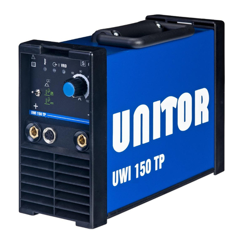
Unitor UWI 150 TP User manual

Unitor
Unitor UPC 1041 User manual

Unitor
Unitor UPC-310 TP User manual

Unitor
Unitor UWI 320 TP User manual

Unitor
Unitor UNITOR UWI 400 User manual
Popular Welding System manuals by other brands

ESAB
ESAB Retrofit Aristo Mig 4004i WeldCloud instruction manual

ESAB
ESAB Heliarc SR-9 Instruction manual and spare parts list

Abicor Binzel
Abicor Binzel ABIMIG 0 Series operating instructions

HÜRNER
HÜRNER HST-S-315 user manual

GYS
GYS GYSPOT Combi 230 Pro user manual

Forsthoff
Forsthoff FORSTHOFF-D operating instructions