Unitor UWI 500 TP User manual

Revision date: 10/07/2017 Page 1 of 40
Instruction manual
Unitor Welding Inverter
UWI 500 TP & UWF 102
MMA, ACA, TIG and Wire welding

Revision date: 10/07/2017 Page 2 of 40
CONTENTS
SECTION PAGE
1. GENERAL DESCRIPTION 3
2. TECHNICAL DATA 4
3. INSTALLATION 7
4. FRONT PANEL CONTROLS 8
5. STICK ELECTRODE WELDING 10
6. AIR CARBON ARC GOUGING 11
7. TIG WELDING 12
8. WIRE WELDING 13
9. ROUTINE MAINTENANCE 18
10. TROUBLESHOOTING 19
11. ORDERING INFORMATION MACHINES 21
12. ORDERING INFORMATION BASIC ACCESSORIES 22
13. TIG AND W1RE TORCHES WITH SPARES 23
14. WIRING DIAGRAM UWI-500TP 26
15. COMPONENTS AND SPARES UWI-500TP 28
16. COMPONENTS AND SPARES UWF-102 30
17. WIRING DIAGRAM FOR UWF-102 32
18. SAFETY INSTRUCTIONS 33
19. NOTES 37
20. UNITOR HANDBOOK FOR MARITIME WELDERS 39
DO NOT INSTALL, OPERATE OR REPAIR THIS EQUIPMENT WITHOUT READING THIS
MANUAL INCLUDING THE SAFETY INSTRUCTIONS

Revision date: 10/07/2017 Page 3 of 40
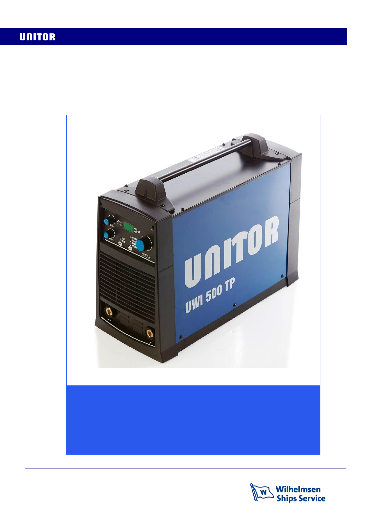
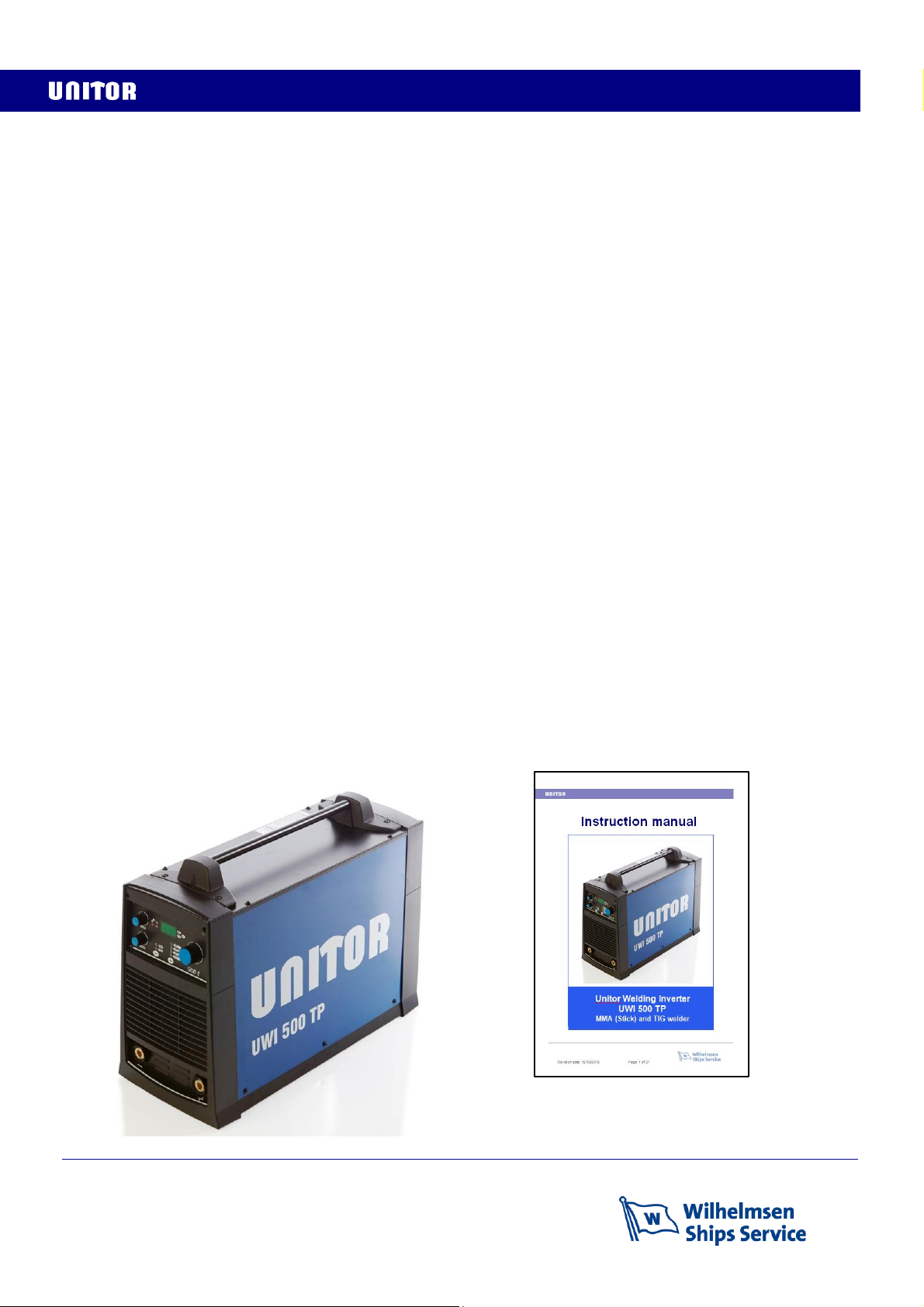
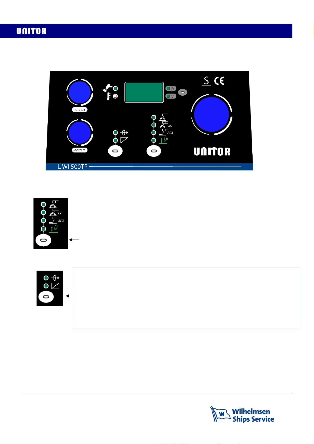
1 GENERAL DESCRIPTION UWI-500TP
Automatic adjustment to any primary voltage between 380 and 440V.
Line Voltage compensation keeps output of the power source constant regardless of fluctuation in
input power from 10% below lowest to above highest rated input voltage.
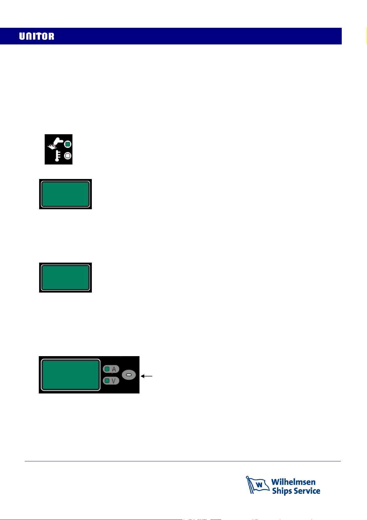
Safe in use. Touchable open circuit voltage only 9V, providing optimal safety for the operator
Adjustable Hot Start for MMA provides optimal arc striking for all electrode types and prevents
electrode sticking.
Adjustable Arc Force for stick electrode welding allows the arc characteristics to be changed for
specific applications and electrodes.
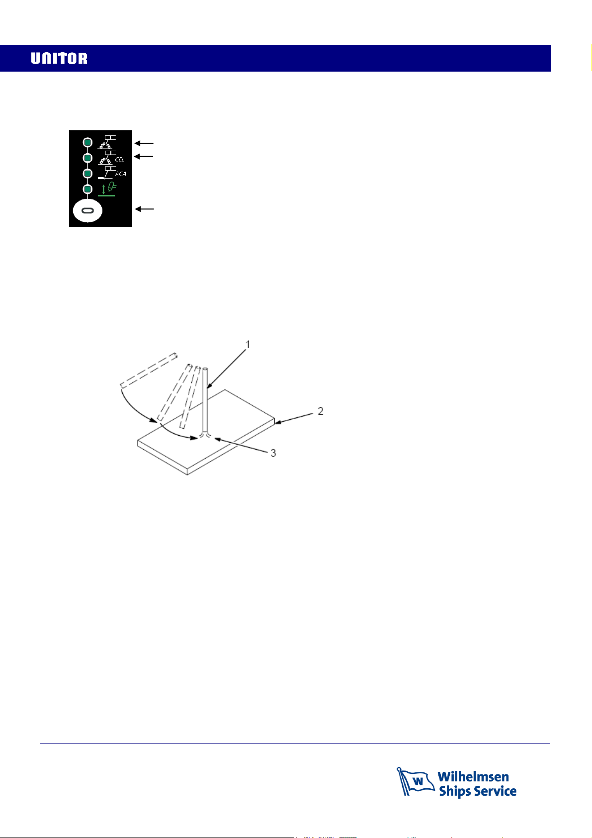
Lift-Start in TIG mode provides easy and soft TIG arc start and remote control from 5 amp to max.
ensures total arc control both during welding and for the down-slope finish of the weld.
Casing of high-grade aluminium and industrial plastic to eliminate corrosion damage also contributes
to low weight, which together with compact outer dimensions provides good portability.
Wind tunnel design for the internal cooling airflow protects electrical components and PC boards
from dirt, dust, debris, greatly improving reliability.
Thermal overload protection with indicator lights helps prevent machine damage if the duty cycle is
exceeded or airflow is blocked.
Total Protection function with indicator light prevents machine damage if one phase in the primary
power supply falls out or if over-voltage is supplied to the machine.
Separate characteristics for welding with standard electrodes, for cellulosic electrodes, for TIG, for
Air Carbon Arc gouging and for Wire welding with or without shielding gas ensures optimal properties
for all processes
The remote amperage control can be used for all processes, and also for two machines in parallel for
up to 1000 Amp. for Air Carbon Arc gouging.
Delivered as machine only, with
primary cable (correct plug must be
added) and instruction manual

Revision date: 10/07/2017 Page 4 of 40
2 TECHNICAL DATA
Type of welding machine
Three-phase static transformer rectifier with frequency converter and DC output.
Standards
EN 60974-10 European Norm for electromagnetic compatibility.
EN 60974-1 European Norm for arc welding appliance: Current sources for welding.
Processes
MMA (Manual Metal Arc welding (stick electrode welding)
TIG Tungsten Inert Gas welding
MIG/MAG Metal Inert/Active Gas shielded welding (wire welding)

Revision date: 10/07/2017 Page 5 of 40
Safety Marking
Suitable for use in areas with increased electric shock hazard
X: Duty cycle
Duty Cycle is the percentage of 10 minutes that the unit can weld at rated load without overheating.
It refers to a 40°C environmental temperature. If the unit overheats a thermal switch stops the output,
the warning light for over-temperature is lit and the cooling fan continues to run. Wait until the
warning light darkens, then reduce amperage or duty cycle before continuing to weld.
I2= Welding current.
Range 5 –500A cover a range from the most small scale thin plate TIG welding to groove
preparations with chamfering electrodes and all normal Air Carbon Arc Gouging.
Parallel connection ability doubles the range.
Ur= No-load voltage
Is the voltage between welding terminals (touchable voltage) when the machine is idle and equipped
with a voltage reduction function for operator safety. Low value means high operator safety, and with
this in mind this machine satisfies the world’s strictest regulation: AS 1674.2-2007 Safety in welding
and allied processes (Australian standard) which allows for maximum 35V.
Note: Mean value measured according to IEC 60974-1 is used in AS 1674.2 and is 9V for UWI-500TP. This will show up as
12,7V on display 6 when V is selected as this instrument displays peak value, not mean value.
U0= Arc striking voltage
When electrode touches work piece the Urvoltage will within a split second jump to this value. It is
important that this value is high enough to enable quick and easy arc start for all welding
consumables.
U2= Arc voltage
This is the voltage present between the output outlets when welding is being carried out, in relation
to a particular set welding current.
The relation between voltage and amperage for the various welding modes are the following:
MMA →U2=20+0,04* I2
TIG →U2=10+0,04* I2
MIG/MAG →U2=14+0,05* I2

Revision date: 10/07/2017 Page 6 of 40
Primary connection
U1= Effective input voltage which must be between 380 and 440V
I1max = Maximum value of input current at the corresponding duty cycle.
I1eff = Effective value of input current at the corresponding duty cycle.
Maximum input power is 26,5 kVA. Power factor 0,85. Duty Cycle 50%
32A slow fuses will be the right fuse size for this machine.
NOTE:
If two machines are to be used in parallel for up to 1000 amp output each machine needs a separate
32 Amp connection.
Cooling
COOLING AF= Forced air cooling (with a fan).
NOTE:
This cooling requires sufficient space to allow free air flow for cooling, a minimum of 50 cm on all
sides is recommended,
Protection class
IP23S= Ingress Protection class. Protection degree of the casing according to EN 60529
2: Protection against object 80mm in length and more than 12mm in diameter
3: Protection from sprayed water at an angle of 60º from vertical
S: Valid at standstill. (Can be used outdoors but not in heavy wind and rain)
NOTE:
Equipment with lower IP class should not be used outdoors.
Thermal insulation class
I.CL.H= Thermal class of the insulating materials and insulation systems.
Class H: resistant up to 180°C.
Conformity to the rules of the European Union
Mark stating conformity to all safety standards and other standards required for sale
and use within the European Union.
Recast Directive
This mark confirms that the product confirms to the RoHS directive which restricts the use of
specific hazardous or restricted substances in electrical and electronic equipment put on the
market in the European Union.
Restricted substances are:1.Lead (0.1%) 2. Mercury (0.1%) 3. Cadmium (0.01%) 4. Hexavalent chromium (0.1%)
5. Polybrominated biphenyls (0.1%) 6. Polybrominated diphenyl ethers (PBDE) (0.1%)

Revision date: 10/07/2017 Page 7 of 40
3 INSTALLATION
Only qualified personnel should perform this installation.
Only personnel that have read and understood this Manual should install and operate this
equipment.
Machine must only be plugged into a receptacle which is grounded in accordance with valid
regulations.
Note
The power switch should be in the OFF position when installing work cable and electrode cable and
when connecting power cord to input power.
Dimensions and weight
UWI-500 UWF-102
Height : 510mm 440mm
Length : 670mm 690mm
Width : 290mm 385mm
Weight : 47kg 17,4kg
Select suitable location
UWI 500TP and UWF-102 have IP23S rating.
Locate UWI-500TP in a dry location where there is free circulation of clean air into the louvers in the
back and out the front of the unit. Ensure minimum 50cm free space on all sides. If free flow of air is
hindered the machine will overheat.
A location that minimizes the amount of smoke and dirt drawn into the louvers reduces the chance of
dirt accumulation that can block air passages and cause overheating.
The UWF-102 has no air cooling.
Avoid tilting
The machine must be placed on a secure, level surface, maximum 15º out of horizontal.
Rear panel functions
1: Primary cable. Mount plug and connect to
socket with 32A slow fuses
2: On/Off switch
3: When lit the Total Protection function has
been activated due to one missing phase
in the power supply. Switch machine off,
and correct the power supply before continuing.
4: Remote control connection.
Note: If remote control is connected it must
be activated by selecting remote control on
the front panel
5: Power supply transformer fuse,
slow, 2A, 500V
6: Control cable to wire feeder (at the bottom)
1
2
3
4
5
6

Revision date: 10/07/2017 Page 8 of 40
4 FRONT PANEL CONTROLS
Select process (1)
Select remote control (2)
Arc force (3)
Arc force increases the short circuit amperage providing a crisper arc, allowing the welder to use
very short arc without sticking the electrode in the melt pool. It is useful when welding with stick
electrodes at low amperages but gives more spatter. Set control to 0 (soft arc) for normal electrode
welding and TIG welding.
Normal stick electrodes
Cellulosic stick electrodes
Air Carbon Arc Gouging
TIG welding
Press button until light for the process is on. No light for wire welding
Control from wire feeder: The wire feeder must be connected to the back panel bottom section
Remote control for electrode holder or TIG torch: Connect to the machine back panel top
section
Press button to turn light for remote control on.
Keep depressed for 3 seconds to activate control from wire feeder.
The display will then show the message: “---“
No light means front panel control
4
3
7
6
5
1
2

Revision date: 10/07/2017 Page 9 of 40
Hot start (4)
Hot start increases the start current for 0,4 seconds: It makes arc striking easier and reduces the
possibility for electrode sticking. With setting for normal stick electrodes the increase can be adjusted
from 0-100% of set current. For cellulosic stick electrodes the increase is up to 200%
Warning lights (5)
Display message: AL.H
The machine has overheated, the fan continues to run, all other functions are disabled.
Check first if the Total Protection LED is ON, if not check that the cooling air is unhindered and flows
freely through the machine.
When the machine has cooled down power will automatically be restored.
Reduce output power setting or operate at a lower duty cycle to avoid repetition
Display message: E.69
There is a fault in the wire feeder software, the fan continues to run, all other functions are disabled.
Disconnect the wire feeder and send it for service.
When another process is selected the machine will function normally.
Display setting (6)
Select button
Select A
The display will show the welding current which is set with adjustment knob (7)
Select V
The display will show no-load voltage when not welding, and arc voltage during welding
Power on warning. Green light when there is power to the +/- sockets.
Alarm light, see display for further information
AL.H
E.69

Revision date: 10/07/2017 Page 10 of 40
5 STICK ELECTRODE WELDING
Select top setting, MMA welding for normal stick electrodes
Select setting CEL for optimal welding characteristic for cellulosic electrodes.
Connect return (ground) cable with good contact directly to the work piece.
Select polarity and amperage as recommended for the electrode and start the arc as follows:
Drag electrode across work piece like striking a match and lift electrode slightly after touching work.
If arc goes out the electrode was lifted to high or the hot start setting is too low.
If electrode sticks to work piece, use a quick twist to free it before it becomes too warm.
If that is difficult switch off the machine or disconnect the electrode holder from the electrode before
restart
Hot start
Setting right level for hot start makes arc striking easier and reduces the possibility of electrode
sticking. If arc start is difficult the hot start setting should be increased until the arc starts satisfactory.
Arc Force
Use no or low Arc Force setting for smooth running electrodes like LH and SPECIAL.
Increased setting provides optimal characteristics for stiffer, more penetrating electrodes like E6010
types, chamfering electrodes like CH2 and electrodes for ACA gouging.
Increased arc force may also be an advantage in position welding
Normal coated electrodes
Electrodes with cellulosic coating
1 Electrode
2 Work piece
3 Arc
Select button

Revision date: 10/07/2017 Page 11 of 40
6 AIR CARBON ARC GOUGING
Select ACA gouging on the front panel.
Select maximum Hot start and Arc force.
Connect electrode holder to plus (+) polarity.
Connect return (ground)cable to negative (-) polarity with good contact directly to the work piece.
If possible bring machine to the work place with a primary cable extension instead of welding cable
extensions.
If welding cable extensions are required 95mm2 is recommended.
Set correct amperage for the selected electrode size
For larger electrodes than 8mm more than 500A may be required. Two machines may then be used
in parallel as follows:
- Set both machines to identical parameters with ACA as selected process and with maximum
Hot start and Arc force
- Set both machines to remote control and if extensions are necessary use same length
remote control cables from each machine to the work site where the remote control parallel
connection kit, product number 676973, is used to connect both machines to the same
remote control
- If remote control is not used both machines should be set to the same ampere value on the
displays, half of the required value for the electrode
- Return cables from both machines should be of equal length and clamps should be
connected close together directly on a clean part of the work-piece. 95mm2 cable is
recommended.
- Welding cables from both machines must be of equal length to the work site where the
parallel connecting three-way connector DIX70 male-female-female, product number
632901 is used to connect both machines to the same Air Carbon Arc torch (product
number 528703). A connector conversion is required here, product number 634121.
Select button

Revision date: 10/07/2017 Page 12 of 40
7 TIG (GTAW) WELDING
Select TIG process and connect the TIG torch to the
regulator with flow control. The torch should have gas valve
on the handle.
Connect TIG torch to the negative (-) terminal of the
machine.
Connect return (ground) cable with good contact directly to
the work piece.
Avoid long welding cable extensions if possible.
Use remote control attached to the torch
With the TIG process normal open-circuit voltage is not present before tungsten electrode touches
and lifts from work piece. Only a low sensing voltage is present between electrode and work piece.
The solid-state output contactor does not energize until after electrode is touching work piece.
This allows the electrode to touch the work piece without overheating, sticking, getting contaminated
or contaminate the work piece.
Start the arc as follows:
Turn gas on.
Touch tungsten electrode to workpiece at weld start point.
Hold electrode to workpiece for maximum 1-2 seconds, and slowly lift electrode.
This may be done by tilting the electrode holder sideways until the gas nozzle touches the
wirk piece and the electrode is lifted.
The arc is formed when the electrode is lifted.
.
During welding the operator has continuous control of amperage and arc with the remote control on
the torch.
Stop the arc as follows:
Slope down welding current at convenient speed until arc stops
Hold the torch over the finishing point for a short while to provide gas shield and avoid
oxidation.
Close off gas flow
1 Electrode
2 Workpiece
Lift carefully and the arc will
be established
Touch the electrode to the work
piece. Only sensing voltage will
be present
2 Workpiece
TIG welding

Revision date: 10/07/2017 Page 13 of 40
8 WIRE WELDING (MIG/MAG, GMAW, FCAW)
The wire feeder UWF-102 Air is a wire feeder specially
developed for the multi-process welding power source
UWI-500TP.
By connecting UWF-102 to UWI-500TP it is, in addition
to wire welding, also possible to do stick electrode welding
and Air Carbon Arc gouging from the wire feeder without
reconnecting
Connecting UWF-102 to UWI-500TP and shielding gas
The wire feeder is delivered with the required hoses and
cables for connection to shielding gas and UWI-500TP
4m gas hose for shielding gas is connected here:
The other end has nut with 3/8” RH threads for
connection to a shielding gas regulator on a gas
cylinder
4m remote control cable for connection to the back side
of UWI-500TP is connected here:
The 4m connection cable for welding current is
connected here:
NOTE:
Correct polarity for the welding process must be selected
when connecting the welding cables to correct polarity for
welding and return at the power source.
If cable extensions are used the return cable should also be
extended to the work place for polarity selection there.
The welding cable should always be connected to the + or
–terminals on the front panel of UWI-500TP to ensure that
correct polarity for the wire is used is used.
Positive + polarity is normally used for gas-shielded wires
Negative –polarity is normally used for self-shielded wires
The 4m remote control cable from UWF-102 is connected at the back of the UWI-500TP here:
Select control of UWI-500TP from UWF-102 with the selection knob 2 on the front panel of
UWI-500, see section 4

Revision date: 10/07/2017 Page 14 of 40
Front panel controls
Select process (1)
For Stick electrodes:
Select + or –according to electrode spesification and connect this polarity from the welding machine
to the back of the wire feeder. The other polatity is return cable from workpiece to welding machine
For ACA gouging:
Connect to + polarity from the welding machine to the back of the wire feeder. The - polatity is return
cable from workpiece to welding machine
Set welding current on potmeter 5. Dispay 7 will show the set welding current in Ampères when
electrode welding or Air Carbon Arc gouging is selected
1
2
3
4
5
6
7
8
9
10
11
12
Coated electrodes, (not cellulosic)
Air Carbon Arc gouging
Select button
Wire welding (MIG / MAG / FCAW)
Wire welding torch connection
Stick electrode holder and ACA torch connection

Revision date: 10/07/2017 Page 15 of 40
Select wire welding process
Connect proper polarity for the wire from the front of the welding machine to the back of the wire
feeder, and the return cable from the work-piece to the welding machine
Select trigger function (2)
2-stroke is used for shorter welds, 4-stroke is used for long continuous welds so that the welder does
not have to keep the trigger pressed through the whole welding sequence
Set shielding gas flow and post gas time (3)
Press again for 2 seconds and the letters P.G. will appear on Display 7 and gas post flow in seconds
will appear on Display 8. Adjust post flow time with potmeter 6 if required, then press again to store
the value.
Cold wire feed (4)
Set wire feed sped (5)
Set wire feed speed on potmeter 5. Dispay 7 will show the set wire speed in m/min when wire
welding is selected
Set welding voltage (6)
Set wire feed speed on potmeter 6. Dispay 8 will show the set voltage when wire welding is selected
Adjust inductance (12)
When welding with a short arc lower inductance will give crisper arc and easier arc start. The bead
will become taller and narrower.
More inductance will give a softer arc and flatter wider bead appearance. Too much inductance will
give difficult arc starts.
Low thermal conductivity materials like stainless steel need more inductance to get acceptable
wetting with short arc.
4-stroke function. Press and release trigger to start wire feed and welding, then
Press and release trigger to stop wire feed and welding.
2-stroke function. Press trigger to start wire feed and welding, and keep trigger pressed.
Release trigger to stop wire feed and welding.
Connect shielding gas from gas cylinder flow regulator to the back of the wire feeder
and open for gas.
Press and release this button and the gas valve in the wire feeder will open for 15
seconds to allow adjustment of correct flow on the cylinder regulator.
When wire spool is properly inserted and drive rolls closed this button is pressed to
feed the wire through to the torch without voltage / welding current present, and
without shielding gas flow.

Revision date: 10/07/2017 Page 16 of 40
Warning signals
9: The welding machine has overheated and needs cooling
See ch.4:5
10: “HOLD”: The displays 7 and 8 show last real measured
values. The light will go out when welding starts again
and real values will be shown
11: When lit this light informs that power is available at the wire feeder terminals
Display 8 warning messages
Remote control from wire feeder has not been selected on the welding machine, see
ch.4:2
When communication between welding machine and wire feeder does not function
properly message Err.C0, Err.C11 or Err.C12 will be displayed.
The welding machine has overheated and needs cooling. This message will be
displayed together with warning light 1. See ch.4:5
Spool box and wire feed compartment
UWF 102 wire feeder has a separate spool box outside
The wire feed compartment. The spool box is angled
slightly upwards for operator ease of use, and facilitates
all standard spool sizes.
Spool box lid
Note: Keep closed when welding, the wire will then be
Electrically live.
Spool box
Shaft for wire spool
Set Gen
Err.Cxx
AL.HEA
Locking stud.
Fits corresponding
hole in spool and
prevents spool from
sliding on the shaft
Friction brake adjustment.
Correctly set the brake will stop the spool at
the instant welding stops to prevent wire from
unwinding from the spool, but not hold back so
much that smooth wire feeding is prevented
Locking
cap for
shaft
Wire feed system
with drive rolls and
adjustment of the
drive roll pressure in
the wire, see next
page.

Revision date: 10/07/2017 Page 17 of 40
Wire loading
Pull the pressure arm (1) outwards to release
the spring loaded wire feed drive rolls (2).
Check that correct wire feed drive rolls
for the wire is installed with correct
groove size in position (see next section),
if not unscrew the fixing caps (3+4)and
turn rolls or replace with correct rolls.
Place the wire spool in place on the wire
spool spindle.Make sure that the locking
stud engages in the corresponding hole
in the wire spool.
Carefully detach the end of the wire from
the spool, cut the bent portion of wire off
and straighten the first 10cm.
Thread the wire through the ingoing guide
tube (5), over the drive roll (3), through the
intermediate guide (6), over the drive roll (4)
and into the outgoing guide tube (7).
This guide tube starts very close to drive roll
(4) and reaches through the torch connector to the torch
Close the wire feed drive rolls (2) and latch the spring loaded pressure arm (1) in place. The roll
pressure on the wire is adjusted with the screw on the pressure arm. It should be tightened
sufficiently to ensure smooth feeding of the wire and still slide on the wire if the wire is stopped by a
blocked torch nozzle
Drive rolls
V-groove smooth drive rolls are used for all solid vires except aluminum.
U-groove drive rolls prevents deformation and is specially designed for Aluminum which is soft and
will be deformed when sufficient pressure for smooth feeding is applied towards a V-groove drive
roll, resulting in poor welding results.
Knurled V-groove drive rolls are specially developed for flux-cored wires and provides excellent grip
on the hard surface of these wires without requiring a pressure that will deform these tubular wires.
1
2
3
4
2
5
7
6

Revision date: 10/07/2017 Page 18 of 40
9 ROUTINE MAINTENANCE
Checkpoint
Action
Interval
Primary plug
and socket
Check connections
and stretch relief
3 months or more
often if needed
Primary cable
Check for damage
and replace if
necessary
3 months or more
often if needed
Primary cable
stretch relief
and connection
Check for damage
and tightness
3 months or more
often if needed
Labels
Replace damaged or
unreadable labels
3 months or more
often if needed
Internal dust
and dirt
Blow out or vacuum
inside
6 months or more
often if needed
Welding current
sockets
Check and clean
3 months or more
often if needed
Cable
connectors
Check, clean if
needed and tighten
Prior to use /
every 3 months
Welding cables
Repair or replace if
damaged
Prior to use /
every 3 months
Electrode
holders and
torches
Check, clean and
replace if damaged
Prior to use /
every 3 months
Ground clamps
Check tightness and
clean contact points
Prior to use /
every 3 months
Remote
controls,
if relevant.
Check function and
condition of cables
3 months or more
often if needed

Revision date: 10/07/2017 Page 19 of 40
10 TROUBLESHOOTING
SYMPTOM
POSSIBLE REASON
SOLUTION
No output, no
warning light, fan
not running
Primary power does not
reach the machine
Mains fuses blown
Machine is not plugged in
Broken primary cable
Cable connection to machine is loose
Machine not switched on
On/off switch damaged
No output, yellow
warning light
One phase is missing in
primary power supply
Check the supply power from the vessel for blown
fuses, loose connections etc.
Thermal protection
activated
Used at too high duty cycle, wait until machine has
cooled down and power returns.
Weld with more breaks or lower current
Cooling air flow is hindered, remove obstructions
Heat development in loose electrode holder or
ground cable connections
Broken fan, repair or replace
Too much dirt in power source compartment, clean.
No arc, no
warning light
Incomplete circuit
Check ground cable and torch connections.
Unstable arc
Polarity
Check that polarity on the machine matches the wire
Poor contact
Check ground clamp and torch connections
Unclean work piece
Clean

Revision date: 10/07/2017 Page 20 of 40
RESETTING SOFTWARE
Unidentified software problems may prevent the
welding power source from functioning correctly.
If normal troubleshooting does not help the below
software reset procedure should be used.
The reset procedure involves complete
restoration of the default values, parameters and
memory settings to original values.
UWI-500TP
-Switch the welding machine off.
-While pressing buttons A and B switch the
machine on.
-Release buttons A and B.
The message REC will appear on the display.
When the message disappears the machine is
ready
UWF-102
-Switch the welding machine off and connect
the wire feeder.
-While pressing buttons C and D switch the
machine on.
-Release buttons C and D.
The message rEC FAC will appear on the
displays of the wire feeder.
When the message disappears the machine
is ready
A
B
D
C
This manual suits for next models
1
Table of contents
Other Unitor Welding System manuals

Unitor
Unitor UPC 838 User manual

Unitor
Unitor UPC 1041 User manual

Unitor
Unitor UWI 203 TP User manual

Unitor
Unitor UNITOR UWI 400 User manual

Unitor
Unitor UWI 150 TP User manual

Unitor
Unitor UWI 320 TP User manual

Unitor
Unitor UPC 1041 User manual

Unitor
Unitor UWI 202 User manual

Unitor
Unitor UPC-310 TP User manual

Unitor
Unitor UNITOR UWI 400 User manual