Universal Laser Systems ULS 1720C User manual

OPERATIO AD MAITEACE MAUAL
Model ULS 1720C
Universal Laser Systems, Inc.
7707 East Acoma Drive
Scottsdale, AZ 85260
602/ 83-121
Volume I, Rev. 5
April, 1992

TABLE OF COTETS
NOTICE ...........................................................................................................................1
INTRODUCTION............................................................................................................2
SECTION 1 - SAFETY ...................................................................................................3
1.1 SAFETY SUMMARY................................................................................3
1.2 SAFETY LABELS......................................................................................
1.2.1 EXAMPLES OF SAFETY LABELS ..........................................
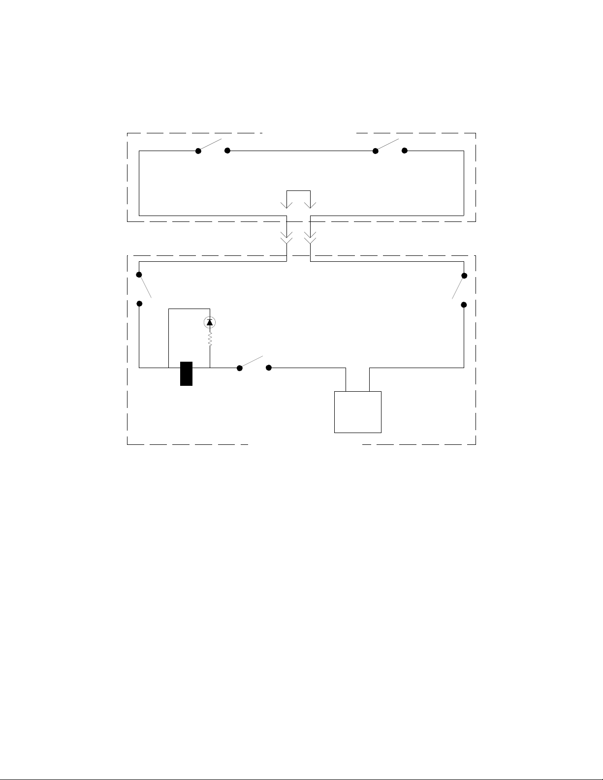
1.3 SAFETY INTERLOCK ..............................................................................5
1. ELECTRICAL SAFETY ............................................................................5
SECTION 2 - INSTALLATION......................................................................................7
2.1 CAUTIONS ................................................................................................7
2.2 SET UP PROCEDURE ..............................................................................7
2.2.1 VENTILATION PROCEDURES ................................................8
2.2.2 CONNECTION WITH COMPUTERS .......................................9
2.2.3 DIP SWITCH LOCATION..........................................................9
2.2. RS-232 SERIAL CABLE CONFIGURATION...........................10
SECTION 3 - OPERATION............................................................................................11
3.1 BASIC OPERATING PROCEDURE ........................................................11
3.2 TURNING THE LASER SYSTEM ON.....................................................11
3.2.1 EMERGENCY OFF SWITCH ....................................................11
3.3 CONTROL PANEL LAYOUT...................................................................12
3. OPERATION CONTROLS........................................................................13
3.5 SHUTTER CONTROLS ............................................................................15
3.6 PROCESSING SPEED CONTROLS.........................................................15
3.7 LASER CONTROLS..................................................................................17
3.8 SOFTWARE CONTROLLED POWER CHANGE (optional) ..................20
3.9 FOCUSING PROCEDURE........................................................................20
3.10 COMMAND SYSTEM ..............................................................................22
3.11 VIEW POSITION INDICATOR ................................................................22
3.12 LASER PROCESSING AREA...................................................................22
SECTION - MAINTENANCE .....................................................................................2
.1 SAFETY SUMMARY................................................................................2
.2 GENERAL CLEANING.............................................................................25
.3 OPTICS CLEANING..................................................................................26

.3.1 FINAL FOCUS LENS .................................................................27
.3.2 FOURTH MIRROR CLEANING................................................28
.3.3 THIRD MIRROR CLEANING ...................................................28
.3. SECOND MIRROR CLEANING................................................29
.3.5 BEAM WINDOW CLEANING ..................................................30
. TOP DOOR ADJUSTMENT .....................................................................30
.5 SET SCREW REPLACEMENT.................................................................31
.6 FIRST MIRROR CLEANING AND BEAM ALIGNMENT.....................32
.7 LASER REPLACEMENT..........................................................................37
.8 FIGURES FOR MAINTENANCE SECTION ...........................................39
SECTION 5 - WARRANTY ........................................................................................... 3
5.1 ONE YEAR LIMITED WARRANTY ....................................................... 3
5.2 IN-WARRANTY SERVICE ......................................................................
5.3 OUT-OF-WARRANTY SERVICE............................................................
5. REPACKAGING FOR SHIPMENT ..........................................................
5.5 FIELD SERVICE........................................................................................
APPENDIX A - DIP SWITCH SETTINGS TABLE ......................................................A1
APPENDIX B - LASER SYSTEM SPECIFICATIONS .................................................B1
APPENDIX C - LASER OPERATING PARAMETERS ...............................................C1

1
This publication and its contents are proprietary to Universal Laser Systems, Inc., and are
intended solely for the contractual use of Universal Laser Systems, Inc. customers.
This publication and its contents may not be reproduced or distributed for any other purpose
without the written permission of Universal Laser Systems, Inc.
OTICE
Universal Laser Systems, Inc. does not assume any liability arising out of the application or use
of any products, circuits or software described herein. Neither does it convey a license under its
patent rights nor the patent rights of others. Universal Laser Systems, Inc. further reserves the
right to make any changes in any products described herein without notice. This document is
subject to change without notice.

2
ITRODUCTIO
The ULS series of Laser Processing Systems are designed to provide the user with the flexibility
of computer control combined with a wide variety of functions.
The main features of the ULS 1720C system are:
•
Air cooled, RF driven 20 watt C02 laser based on the latest technology in sealed carbon
dioxide devices.
•
Digital laser controller providing a wide range of parameters for material processing.
•
Class I safety enclosure.
•
Fast X-Y laser beam positioning system for quality laser processing at high speed.
•
Large material processing area.
•
Extended vertical adjustment.
•
Two types of computer interface -- parallel (Centronics) and serial (RC-232C).
te: Serial interface is not available if the High Speed Raster Engraving Option is
installed.
•
A variety of controls for quick setting of parameters.
•
Complete emulation of HP 7 75 and Roland DXY 1300 B size plotters.
•
Compact design.

3
SECTIO 1 - SAFETY
Please read this section before operating the equipment.
1.1 SAFETY SUMMARY
1. Exposure to laser radiation may produce physical burns and can cause severe eye damage.
2. Exposure to the beam may cause ignition of combustible materials.
3.
When perat r r maintenance pers nnel are w rking with the laser beam
"O" and any f the safety interl cks defeated, r c vers rem ved, laser safety
glasses must be w rn.
Care must be exercised not to place one's self or reflective
objects in the path of the beam. Never view laser beam radiation directly or by specular
reflection. Failure to wear appropriate eye protection can result in severe eye damage.
Please contact ULS with any questions concerning laser safety before operating the system.
. Operation and maintenance must be accomplished in accordance with this manual.
5. The laser in this system emits radiation at a wavelength of 10.6 microns in the infrared
invisible spectrum.
6. A solenoid operated shutter is located between output of the laser and top compartment of
the system. In the OFF position the shutter completely blocks the laser beam before it
enters the work area. Shutter control is located on the lower right corner of the system
control panel. When the shutter switch is open, the LED is on. If any interlocked doors are
open, the shutter blocks the beam regardless of the position of shutter control switch.
OTE: The LED indicates only whether the shutter switch has been set to open or closed.
It does not indicate the physical position of the shutter itself.
7. Under regulations established by the Center for Devices and Radiological Health of the
Food and Drug Administration, the laser contained in this system is a Class IV instrument.
ULS systems are Class I instruments as long as no interlocks are defeated and cover panels
are not removed.
8. Improper use of controls and adjustments or performance of procedures other than those
specified in this manual may invalidate the Class I rating and result in hazardous laser
radiation exposure.
9. ULS systems are specifically designed to comply with CDRH performance requirements
under 21CFR 10 0.10 and 10 0.11. No guarantees of suitability or safety are provided for
any use other than those specified by Universal Laser Systems, Inc.

1.2 SAFETY LABELS
According to CDRH standards, all interlocked and non-interlocked covers that allow access to a
Class IV laser beam must have appropriate laser safety labels attached to them. These labels
must be visible to personnel prior to the removal of the covers. Additional labels must be
installed inside the machine and be visible if the covers are removed from the machine.
Labels that provide manufacturer's name, date of manufacture, description of product, model
number, serial number and compliance statement must also be visible on the outside of the
machine. All CDRH required labels are properly affixed to the machine in the appropriate
locations at the time of manufacture. These labels are not to be removed. If they become
damaged or removed for any reason, please request additional labels from the manufacturer.
1.2.1 EXAMPLES OF SAFETY LABELS
Label Positions
Lower left corner of rear panel, on the outside of
the machine
Lower left corner of rear panel below
manufacturing label (see above label
information).
Above beam entrance aperture in top
compartment.
Laser Processing System Manufactured By:
Scottsdale, Arizona
Model No:
Serial No:
Date of Manufacture:
Made in USA
This equipment conforms
to provisions of
US 21 C R 1040.10
and 1040.11
AVOID EXPOSURE
INVISIBLE LASER RADIATION
IS EMITTED ROM THIS APERTURE

5
Label P siti ns
Inside front door (visible when door is open).
Bottom panel (visible when door is open)
Inside top door (visible when door is open).
Rear panel of top compartment (visible when top
cover is removed).
One on each side of interlock defeat tool (visible
when interlock tool is installed).
Bottom panel on the right and left sides and in the
back (visible when front door is open and through
lexan panels).
1.3 SAFETY ITERLOCK
The laser system incorporates a safety interlock having an electrical potential of 2 V DC
between terminals. When the top enclosure of the chassis is removed, the terminals of the
interlock connector at the front of the enclosure are no longer in contact and the laser beam will
be blocked by the shutter. A shorting plug, called an interlock defeat tool, is provided to override
the safety interlock for testing and alignment procedures only. The diagram below is an electrical
schematic detailing the interlock system and the interlock defeat tool.
Cauti n: The interlock defeat tool is utilized only when the top enclosure must be removed
for testing purposes and beam alignments.
Laser safety glasses must always
be w rn when the defeat t l is in use.
Failure to wear appropriate eye
protection can result in severe eye damage.
1.4 ELECTRICAL SAFETY
A NEMA type 1 service box mounted to the right side of the machine contains all of the exposed
120 Volt AC in the system. The box encorporates a lockable electical disconnect and a screw
driver is required to open the lid. This box should only be accessed by qualified service personel
DANGER
INVISIBLE LASER RADIATION WHEN OPEN
AND INTERLOCK AILED OR DE EATED.
AVOID EYE OR SKIN EXPOSURE TO
DIRECT OR SCATTERED RADIATION.
Interlocked Panels
DANGER
INVISIBLE LASER RADIATION WHEN OPEN
AVOID EYE OR SKIN EXPOSURE TO
DIRECT OR SCATTERED RADIATION.
Non-interlocked Panels

6
and only for the purpose of servicing the equipment contained within. The service box should
remain closed at all other times.
24 volt
Power
Supply
Shutter
Solenoid
Shutter
Control
Switch
Sutter
Open
LED
ront Door
Interlock Left ront Door
Interlock Right
Top Door
Interlock Left Top Door
Interlock Right
TOP ENCLOSURE
BOTTOM ENCLOSURE
Interlock
Defeat Tool
Electrical Schematic of Interlock System

7
SECTIO 2 - ISTALLATIO
2.1 CAUTIOS
• Install the system on a flat stable base 18-2 " high, only in the upright position. Ideally,
the top of the system should be mid thigh to waist high.
• Avoid places where the system may be exposed to high temperatures, dust, or high
humidity (humidity exceeding 60% or where the temperature is near the dewpoint).
• Avoid places where the system may be exposed to high levels of vibration or electrical
noise. We recommend using a high quality surge protector (20 Amp capability) to protect
the laser system's electronics.
• The power supply cord and input/output cables for the computer should be connected
firmly to avoid disconnection or malfunctioning during operation. Use grounded (3 prong)
outlets only. Do not defeat the ground connection under any circumstances.
• When the power is turned on, the system performs an automatic origin setting procedure
and the arm and focusing optics carriage move. Keep hands or objects out of the path of
the arm\optics carriage.
• When not using the system, unplug the power cord.
• NEVER lubricate any of the mechanical parts!
• Do not apply any pressure or shock to the arm or optical carriage.
• When the X-Y rails become dirty, wipe them off with a soft dry cloth. If the dirt is severe,
wipe it off lightly with alcohol. Do not use water. D n t use silic ne-impregnated
cl th, neutral detergents r rganic s lvents. See the maintenance section for details on
cleaning of the system.
• Do not move arm or optical carriage manually if the power to the system is on!
2.2 SET UP PROCEDURE
The following is a description of the basic procedure for connecting the ULS 1720C laser system
to a computer for the first time:
1. Install the system on a flat, stable stand. A stand from 18 to 2 inches in height will
provide the most comfortable working height. Custom designed, ergonomic stands are
available from ULS.

8
2. Connect the fume exhaust tube on the machine to an external exhaust unit (see the exhaust
system section below for details). (For the optional ULS closed loop exhaust, connect the
two hoses between the laser system and the filtration unit and plug the filtration unit into an
AC power source.)
3. Connect the laser system to the computer. Both serial and parallel connections are
available. (The system is set for parallel connection at the factory.) Most software is set to
run in parallel mode, so switching interfacing to serial mode is not normally required.
te: Serial interface is not available if the High Speed Raster Engraving Option is
installed.
If your software requires serial interfacing, continue with Steps -7, otherwise skip to step 8.
. The cover must be removed to access the DIP switches. To Remove the top enclosure:
a. Loosen enclosure hold down screws inside front door at the left and right side that go
up through the frame. Remove knob for Z stage (table height adjustment).
b. Tilt the front of the enclosure up approximately two to three inches until the enclosure
can be pulled forward without obstruction.
c. Carefully pull the enclosure forward and up until off of the machine. Set the cover
out of the way being careful not to scratch it.
5. Set the type of interface to serial using the DIP Switches. Refer to the DIP switch location
section below and Appendix A DIP Switch Settings Table.
6. Set the communication parameters for the serial port using the DIP switches. Refer to the
DIP switch location section below and Appendix A DIP Switch Settings Table. The proper
communication parameters will depend on the computer and software being used, refer to
the computer and software manuals for details.
7. After the setup for serial communication is completed, replace the top cover.
8. Connect the AC power cord.
The system is now ready for initial power up. Turn to Section 3 - Operation for details.
2.2.1 VETILATIO PROCEDURES
To properly exhaust fumes and smoke from the material surface during processing, an exhaust
unit moving a minimum of 00 cfm of air is required. Rigid duct work should be used between
the blower unit and the laser system. Use duct work with a diameter that matches the blower unit
and reduce the duct work to four inches just before the point of attachment to the laser system.

9
Locate laser system where a straight connection to the duct work can be achieved. A short piece
of flexible hose should be used to connect the laser system to the rigid duct work.
The exhaust system should be equipped with an on/off switch and wired in accordance with local
electrical codes. We recommend plugging the laser system into a 110V switched outlet,
controlled by the on/off switch for the ventilator, to ensure the laser system cannot be operated
without the ventilator. It is also advisable to power the laser system through a surge protector to
prevent damage to the electronics and laser.
Installation of the ventilation system should comply with all applicable local and government
regulations. We recommend the use of licensed contractors for installation of the exhaust
system.
2.2.2 COECTIO WITH COMPUTERS
There are two methods for establishing a connection with the computer:
•
Parallel connection (Centronics)
•
Serial connection (RS-232C)
te: Serial connection is not available if the High Speed Raster Engraving Option is installed.
The system is set for a parallel connection at the factory. This will work well with the majority
of computers and software packages. To change to a serial interface connection refer to the "DIP
Switch Setting Table" in Appendix A and set the DIP switch settings to match the settings
required by the software being used.
2.2.3 DIP SWITCH LOCATIO
There are two DIP switch blocks on the main control board for the laser system and the cover
must be removed to access them. Each block contains ten switches and the two blocks are
referred to as DIP Switch one and two.
1. DIP Switch 1 - Located on the right side of the system (under top enclosure) on the printed
circuit board with the parallel and serial interface connections. DIP Switch 1, marked
"DSW1", has 10 small switches, and is located next to the parallel interface connection.
This switch is used to select the interface (parallel or serial), set field size, and character
font, etc. For details refer to "DIP Switch Setting Table" in Appendix A.
2. DIP Switch 2 - Located on the right side of the system (under top enclosure) on the printed
circuit board with the parallel and serial interface connections. DIP Switch 2, marked
"DSW2", has 10 small switches, and is located next to DIP Switch 1.

10
This switch is used to set the data format and baud rate when the serial interface is used.
For details refer to the "DIP Switch Setting Table" in Appendix A.
2.2.4 RS-232 SERIAL CABLE COFIGURATIO
To use the serial connection on the laser system, the proper serial cable must be used. The
diagram below describes the serial cable configuration required.
.G.
TxD
RxD
RTS
CTS
DSR
S.G.
DCD
DTR
(1)
(2)
(3)
(4)
(5)
(6)
(7)
(8)
(20)
.G.
TxD
RxD
RTS
CTS
DSR
S.G.
DCD
DTR
(1)
(2)
(3)
(4)
(5)
(6)
(7)
(8)
(20)
DCD
RxD
TxD
DTR
S.G.
DSR
RT5
CTS
Ring Indicator
(1)
(2)
(3)
(4)
(5)
(6)
(7)
(8)
(9)
.G.
TxD
RxD
RTS
CTS
DSR
S.G.
DCD
DTR
(1)
(2)
(3)
(4)
(5)
(6)
(7)
(8)
(20)
DSUB-9 pin DSUB-25 pin
Pin No. Pin No.
Pin No. Pin No.
Laser System
Laser System
IBM-PC/AT
IBM-PC or PC/XT
XY-RS-14, XY-RS-34 CABLE
XY-RS-14, XY-RS-33 CABLE

11
SECTIO 3 - OPERATIO
3.1 BASIC OPERATIG PROCEDURE
1. Turn power to the system ON.
2. Insert the material to be processed.
3. Adjust the focus (reference Section 3.8).
. Close all access doors.
5. Choose a laser power setting (reference Section 3.6).
6. Set the processing speed (reference Section 3.5) (can also be set from software).
7. Be sure the shutter switch is in the open position.
8. Be sure the external exhaust is on.
9. Transmit drawing data from the computer.
Laser processing of the material should now begin.
3.2 TURIG THE LASER SYSTEM O
Power to the system is controlled by two momentary pushbutton switches found on top of the
electrical service box mounted on the right side of the system. To turn the system on press and
release the green on switch. To turn the system off press and release the red off switch. Do not
block movement of the motion system when turning the power on.
NOTE: The service disconnect lever on the side of the service box is for use of qualified
service personel only. This lever should be left in the on position.
3.2.1 EMERGECY OFF SWITCH
An emergency off switch located on the top of the service box is provided for operator safety. In
the event of an emergency the mushroom shaped emergency off switch can be pressed and power
to the system will by shut off. Power can not be restored to the system until the emergency off
switch is manually reset by twisting the mushroom cap in the direction indicated on the switch.
Once the emergency off switch is reset the system can be turned on in the normal manner by
pressing the green on button.

12
3.3 COTROL PAEL LAYOUT
1
4
7
MODE
2
5
8
0
3
6
9
DELETE
STORE
PULSE
WIDTH
RATE
PULSE
SELECT
PROGRAM
1
2
3
4
5
6
7
8
X POSITION
Y POSITION
P
P
MODE
2
1
ENTER
REPEAT REPEAT
VIEW
PAUSE
P SPEED
FAST
AUX
TEST
SHUTTER
OPEN
CLOSED
POWER
Laser Control
Keypad
Processing Speed
Controls
Shutter Controls
Laser Control
Display
Operation Controls

13
3.4 OPERATIO COTROLS
POSITIONING KEYS
These keys are used to move the focusing optics manually in any of the arrow directions (four
directions) indicated on the keys. Pressing two adjacent keys together moves the optics carriage
in a diagonal direction.
FAST KEY
AST
Pressing this key together with an arrow POSITIONING key increases the positioning speed at
which the optics carriage moves.
REFERENCE POINT KEYS - P1 AND P2
P
1
P
2
Pressing the P1 or P2 keys will move the optics to the lower left or upper right corners,
respectively, of the engraving area. These keys are typically used to position the system for
checking power or performing a beam alignment. They can also be used in conjunction with the
Test key to manually mark lines on material to indicate the edges of the engraving field or as
alignment marks.
VIEW KEY
VIEW
Pressing this key causes the focusing optics carriage to move to the upper right corner (VIEW
position) of the system.
PAUSE KEY AND LED
PAUSE
When this key is pressed once during processing, the PAUSE LED light illuminates and motion
of the optics is temporarily halted. Pressing this key once more turns the PAUSE LED off and
allows operation of the system to resume. If the system is paused for more than one minute, the
optics carriage will move to the view position (extreme upper right). In either case, the system
will resume operation at the point the pause was initially activated.
CAUTIO: If the laser is in Continuous pulse mode (see section 3.6), the Laser beam might be
on during pause. To prevent damage to work piece, always close shutter switch
(located on control panel) prior to pressing PAUSE key.

1
REPEAT MODE KEY AND LED
REPEAT
MODE
Used to temporarily store drawings that are being sent by the computer. This function allows the
user to repeat the processing of a drawing while freeing up the computer for other tasks. To use,
press the Repeat Mode key and note that the Repeat Mode LED should illuminate (indicating that
all incoming drawings will be stored). Next, send the drawing to the laser system from the
computer. The laser will process the drawing and simultaneously store the drawing in the laser
system's memory. The computer can be used for other tasks once the drawing has been stored.
To repeat the drawing stored in the laser system memory, press the Repeat key (next to the
Repeat Mode key). To turn off the Repeat Mode and erase all stored drawings, press the Repeat
Mode key again and note the Repeat Mode LED has gone dark (indicating that all drawings have
been erased).
CAUTIO: Turning off the laser system power will erase all drawings in the repeat mode
memory.
OTE: The repeat mode will continue to store drawings until it is full (the capacity is 1
megabyte). If multiple drawings are stored in memory, pressing the repeat key
will cause all of the stored drawings to be processed in the order they were
received. If the 1 megabyte limit on memory is exceeded, the laser system
automatically turns off repeat mode (REPEAT MODE LED goes out) and erases
all the drawings.
OTE: Repeat mode is not functional if the High Speed Raster Engraving Option is used
to engrave bitmapped or filled images. The repeat mode and high speed raster
engraving option can only be used together to engrave vector or outline images.
REPEAT KEY
REPEAT
Pressing this key will repeat the drawings stored in the laser's repeat mode memory, starting with
the first drawing stored after the REPEAT MODE key was pressed.
RESET FUNCTION
ENTER VIEW
and
If the ENTER KEY is pressed and held down, then the VIEW KEY is pressed, the system will
perform a soft reset similar to turning the power on and off. This procedure is often sufficient for
resetting the machine after a communication error has occurred. If a more drastic reset of the
system is necessary, the power switch can be turned off and on.
POWER L.E.D.

15
Normally this indicator is illuminated and not flashing when power to the laser system is on. If a
communication error occurs, the indicator will begin flashing. A communication error is caused
by either an improper connection to the computer or the transfer of an unknown command from
the computer. If the L.E.D. begins flashing, identify and remedy the source of the error and then
reset the system.
X-Y COORDINATE DISPLAY
Y POSITION
X POSITION
This displays the position of the focusing optics carriage in millimeters from the extreme lower
left of the current engraving field.
AUX. KEY AND LED
AUX
Not used - Aux. Key may light when PAUSE or REPEAT MODE are used.
TEST KEY
TEST
Used to manually turn the laser power on and off. This key is used to perform beam alignments,
power tests and to manually mark origins (with arrow keys), etc. A dot will appear to the right of
the pulse mode character in the laser control display when the laser is on (see section 3.6 for
details).
3.5 SHUTTER COTROLS
The shutter controls are used to open and close the mechanical solenoid driven shutter which
blocks the beam and stops it from entering the engraving area. The switch will provide power to
open and close the shutter and the LED will glow when the shutter switch is in the open position.
If any interlocked doors are open, the shutter will close to block the beam regardless of the
position of the shutter control switch.
OTE: The LED indicates only whether the shutter switch has been set to open or closed.
It does not indicate the physical position of the shutter itself.
3.6 PROCESSIG SPEED COTROLS
ULS Laser Systems are capable of beam positioning at a maximum speed of 2 cm/sec and this
is the default speed selected when the laser system is powered on. However, for optimum
performance processing speed can be adjusted. The proper processing speed will be dependent

16
on the material being used, the type of engraving or cutting being performed, and the depth of
material removal required.
There are two methods for adjusting the processing speed:
1. Control Panel Processing Speed Adjustment:
SPEED SELECT KEYS
P-SPEED
AND
1 8
THROUGH
Press and hold the P-speed key on the control panel then press one of the processing Speed
keys (1 to 8) to change the processing speed. The processing speed set by each speed key
is as follows:
P-Speed
Key No.
Processing Speed
(cm/sec)
Processing Speed
(inch/sec)
1 3 1.2
2 1.6
3 6 2.
9 3.5
5 12 .7
6 16 6.3
7 22 8.7
8 2 16.5
Processing speed can also be adjusted during engraving, and this is helpful in identifying
the best speed for a particular engraving or cutting job. But, if processing speed is being
controlled by software, speeds should not be adjusted manually during engraving.
2. Computer Software Package Processing Speed Adjustment
Since the ULS 1750Y Laser System emulates an HP-GL plotter device, drawings sent to
the laser system from many software packages can include a processing speed which is
analogous to the plotter pen speed for a plotting device. See your software manuals for
information on how to select plotter pen speeds.
Example:
Using DesignCAD, from within the plot dialogue box the HP-GL command for pen
velocity "VS" can be entered with an appropriate speed 1- 2 cm/sec (this is an HP-GL
velocity command in cm/sec and should not be confused with the P-Speed numbers
on the control panel) before sending the drawing to the laser system.

17
If software resident in Windows is being used, the processing speed can be set through the
ULS Windows printer driver. The procedure for setting speed is explained in the
documentation included with the driver. (This driver is required if Windows is being used
and can be purchased from ULS.)
OTE: If software is being used to control speed then the speed at the control panel should be
set to P-SPEED 8.
OTE: The processing speeds referred to above represent only the maximum straight line
speed of the positioning system. The system will accelerate and decelerate as it
moves and may never reach the maximum processing speed in a complex vector
drawing with many curves and small line segments.
3.7 LASER COTROLS
For optimum engraving performance, the ULS Laser Systems have been designed so that the
laser's power output is directed by a digital control board. This control board produces a square
wave type signal which is essentially a sequence of on and off commands which cycle the laser at
high speed. The Laser Control keypad is used to enter the parameters for the TTL (square wave)
signal which drives the power output of the laser, and an LED display window is provided to
visually display the settings for the laser control signal.
This LED indicates that Laser Power is on.
This LED indicates that Power Change
option is on (see section 3.7)
Power
Setting
Pulse
Mode
Pulse
Width
Pulse
Rate
Figure Showing Typical Laser Control Display
There are three parameters which must be entered to define the characteristics of the signal sent
to the laser, these are pulse width, pulse rate, and pulse mode. Pulse width is entered in
microseconds and defines the length of time the laser remains on during a pulse cycle. The pulse
rate is a relative number and its meaning is dependent on the pulse mode being used.
There are two pulse modes to choose from:
• Proportional Pulse Mode (PPM)
Table of contents
Other Universal Laser Systems Printer manuals
Popular Printer manuals by other brands

Xerox
Xerox Phaser 6200N specification

Epson
Epson TM-L90 series Start here

Konica Minolta
Konica Minolta magicolor 7450 installation guide

FARGO electronics
FARGO electronics DTC510 user guide

Konica Minolta
Konica Minolta Magicolor 4650 brochure

Brother
Brother QL-570VM - B/W Direct Thermal Printer user guide