Universal ECO Series Service manual

3267 Grapevine St | Mira Loma, CA 91752 | T: (888) 866-4765 | F: (888)
806-5557
Low Voltage Power Module Installation & Instruction Manual
ECOSERIESTRANSFORMERS
IMPORTANT SAFETY INSTRUCTIONS
WARNINGS:
•THIS POWER UNIT MUST BE CONNECTED TO A COVERED GFCI RECEPTACLE MARKED “WET
LOCATION” WHILE IN USE
•CAUTION: FOR USE ONLY ON A BRANCH CIRCUIT PROTECTED BY A CLASS A TYPE GROUND
FAULT CIRCUIT INTERRUPTER
•FOR USE WITH LANDSCAPE LIGHTING SYSTEMS ONLY - LANDSCAPE LIGHTING SYSTEMS ARE FOR
OUTDOOR USE ONLY (NOT FOR USE IN DWELLING UNITS)
•THIS DEVICE IS ACCEPTED AS A COMPONENT OF A LANDSCAPE LIGHTING SYSTEM WHERE THE
SUITABILITY OF THE COMBINATION SHALL BE DETERMINED BY CSA OR LOCAL INSPECTION
AUTHORITIES HAVING JURISDICTION
•DO NOT CONNECT TWO OR MORE POWER SUPPLIES IN PARALLEL
•DO NOT MOUNT POWER SUPPLY OR FIXTURES WITHIN 3 METERS (10 FEET) OF A SWIMMING
POOL OR SPA
•DO NOT USE AN EXTENSION CORD WITH THIS POWER SUPPLY
Sizing Transformer
The total wattage (W) - or volt-amps (VA) for LED - of all of the fixtures operated by this transformer
must not exceed the wattage rating of the transformer.
If you are powering halogen lamps, calculate the load by adding the wattage of the lamps in the system.
Make sure the load does not exceed the wattage rating of the transformer.
If you are powering LED lamps or fixtures, calculate the load by adding the volt/amp (VA) values of all of
the lamps in the system. VA is calculated using the following formula:
VA = Wattage
Power Factor
RISK OF SHOCK. Install power unit at least 5 feet
from a pool or spa and at least 10 feet from a
fountain. Where the power unit is installed within
10 feet of a pool or spa, connect unit to a
GFCI protected branch circuit.
RISKOF ELECTRIC SHOCK. Install power
unit at least 5 feet from a pool, spa or
fountain.
Where the power unit is installed (a) indoor
within 10 feet of a pool, spa, or fountain, or
(b) outdoor, connect power unit to a
receptacle protected bya GFCI.

3267 Grapevine St | Mira Loma, CA 91752 | T: (888) 866-4765 | F: (888) 866-
4765
If the power factor of the LEDs is unknown, use 0.7 as the value for this calculation. Once you have
determined the total wattage or total VA value of the run, make sure that the transformer that you have
selected has excess capacity in the event that new fixtures are connected to the system at a later date.
Example: 15 fixtures are each operating a 3W LED lamp with an unknown PF value.
System VA =
15 x 3
= 64.3 VA
0.70
A transformer with a maximum wattage rating of 150W can be utilized.
MOUNT THE TRANSFORMER UNIT
1) Remove transformer door for easy access.
2) Find a solid, flat surface to mount the transformer in a location:
a) That is at least 12 inches between the terminals and ground level with wire terminals
facing down and
b) Six feet or fewer from a 120V supply circuit that is protected by a Class A type ground
fault circuit interrupter
3) Insert load bearing screws or wall anchors into pre-drilled holes that align with the
corresponding keyhole slots on the transformer’s mounting brackets.
4) Secure the transformer’s keyhole slots on the mounting brackets to the load bearing screws
or wall anchors

3267 Grapevine St | Mira Loma, CA 91752 | T: (888) 866-4765 | F: (888) 866-
4765
CONNECT SECONDARY WIRES TO TRANSFORMER
1. Remove the bottom plate from the transformer.
2. Using a flathead screwdriver, adjust the common tap and appropriate low voltage tap on
terminal lug to accept secondary wires.
3. Run the secondary wire cables through the knockouts in the bottom plate.
4. Separate the wires from each pair and strip both approximately one inch.
5. Connect one wire from each pair to the common tap and the other wire to the appropriate low
voltage tap.
6. Secure the wires to the taps by tightening the common tap and the low voltage taps with a
flathead screwdriver.
CHECK VOLTAGE AT EACH FIXTURE
It is very important that the secondary voltage provided to each fixture is within the input voltage range
of the lamp or fixture. Halogen lamps and some LEDs have an input voltage rating of 12V. If the specified
input voltage range is 12V, the input voltage provided to the fixture must be between 11V and 12V. If the
voltage at the socket exceeds 12V, light output of the lamp will be higher but average rated life will
be lower. If the voltage at the socket is lower than 11V, light output will be lower and average rated life
will be higher. Many LEDs have an input voltage range of 10V - 15V, or 10V - 18V. For LEDs with input
voltage ranges, input voltage supplied to the lamp within that range is acceptable.
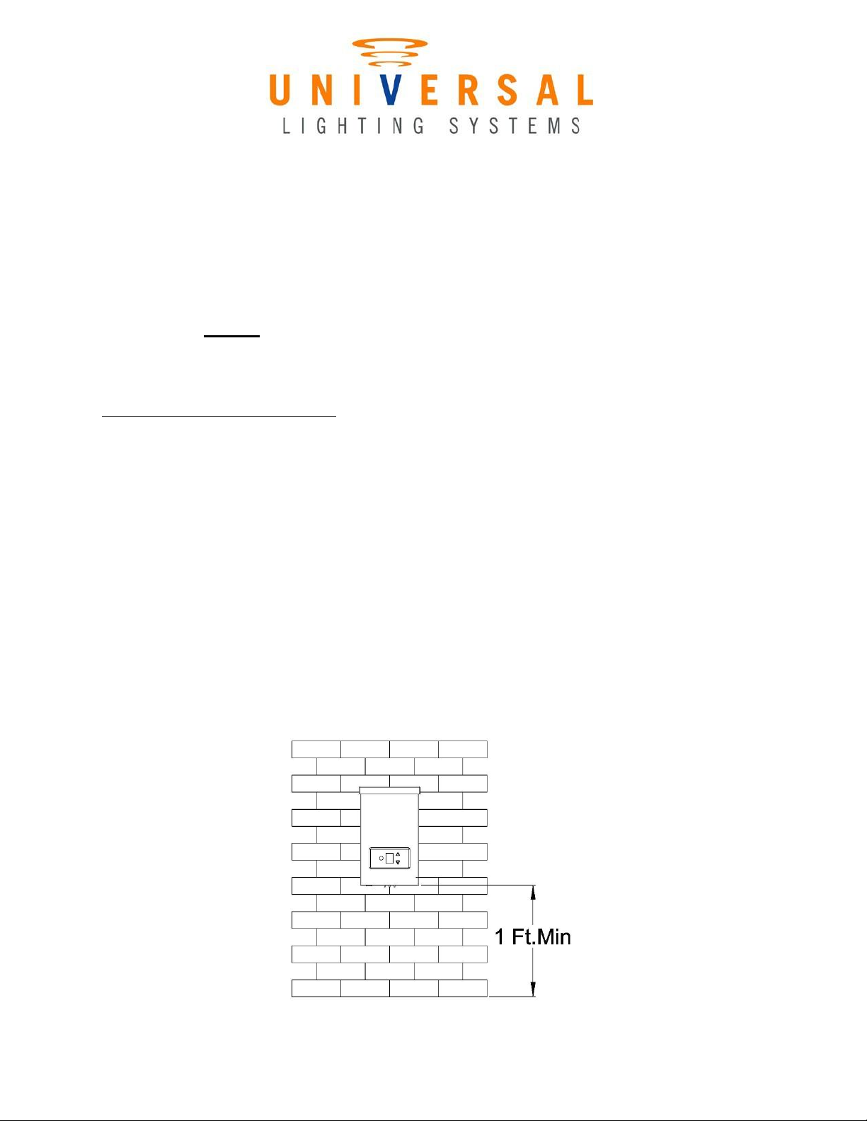
1. Plug the transformer into a covered 120V GFCI receptacle.
2. Switch on the transformer to provide secondary voltage to the fixtures.
3. Using a voltmeter, check the voltage at each fixture.
4. Make sure that the voltage at each fixture is within the specified input voltage range of the
lamps or integrated LED fixtures.
5. If the measured voltage falls outside of the specified input voltage range of the lamps or
integrated LED fixtures, adjust the voltage to the acceptable range by moving the wire to
higher/lower voltage tap.
CHECK OUTPUT AMPS
After checking the voltages on the run, use a clamp-on meter to measure the output current on the low
voltage cable at the transformer for each circuit. Make sure that the output current of the circuit is
below the maximum rated Amperage.
Circuit Size
50 Watts
100 Watts
150 Watts
Amp Rating
4.166A
8.33A
12.5A

3267 Grapevine St | Mira Loma, CA 91752 | T: (888) 866-4765 | F: (888) 866-
4765
Determine System Load and Voltage Drop
Low voltage landscape system voltage drop occurs along the secondary wire and is affected by the
distance of the run, the total wattage of the system, and the gauge of the wire. As a result, fixtures at
the end of the system’s run will receive lower voltage than fixtures near the beginning of the run.
Voltage loss can be minimized in different ways.
Low voltage wire is necessary to run from the secondary power on the transformer to the fixtures it will
operate in the system. Low voltage wire is measured by gauges. Thinner wire has a higher number and
has a lower maximum load. The lower the wire number, the thicker the wire and the more current it can
carry. Consequently, thicker wire reduces voltage drop so it is suggested that 8/2, 10/2, or 12/2 wire is
used for low voltage landscape lighting systems. Below is a table that lists the cable constant value of
different wire gauges:
Wire Gauge
#18/2
#16/2
#14/2
#12/2
#10/2
#8/2
Cable Constant
1,380
2,200
3,500
7,500
11,920
18,960
Example: A 75 ft. run with 100W load using 12/2 wire Voltage Drop = (75 x 100 x 2) ÷ 7500 = 2V. This
means that a 14V tap is needed to deliver 12V to the final fixture on the run.
One way to minimize voltage drop in this example is to spread the load to separate wire runs. Wiring the
system effectively is another way to minimize voltage drop
Determine Input Amps
This unit is provided with a looped wire that is attached to the optional photocell plug. Use a clamp-on
meter around the looped wire to measure the input current. Apply the clamp on the amp meter around
the looped wire to get an input current measurement. Make sure that the input current of the system is
below the maximum rated input current:
Transformer size
50W
100W
150W
Max Input Amps
.416A
.833A
1.25A
If the input current of the system exceeds the max rating of this transformer unit, remove fixtures or
reduce lamp wattages until the input current is reduced to an acceptable level.

OPERATION OF COUNTDOWN TIMER MODULE &
PHOTOCELL
1. The circuit breaker will trip if there is a short circuit, or if the total
lamp wattage exceeds the rated wattage for the transformer.
2. To reset the breaker, you must first resolve the issue that caused the
trip. Only after you resolve the problem, can you reset the circuit
breaker, by pushing “reset” button. If breaker trips again, check for
an overload or a short circuit.
3. Reset Button; Photocell; Digital Display Screen;Up and Down ArrowButton
4. To Operate “Timer”
a. Off=No display
b. On=”0”; always ON
c. Auto=”A”; On at Dusk-Off at Dawn
d. 1,2,3,4,5,6,7,8,9= On at Dusk- Off at 1,2,3,4,5,6,7,8,9 Hrs
1. Timer will stop and reset if unit is exposed to 30sec of light
during countdown.
2. After full countdown is completed, unit will reset only after 1
hours of exposure to lights.
Note: Timer Module is field replaceable and covered under warranty for 1 year.
Please visit us online at WWW.UNLVS.COM, or email us at Sales@unvls.com for a complete list of
products for your landscape lighting needs.
Table of contents