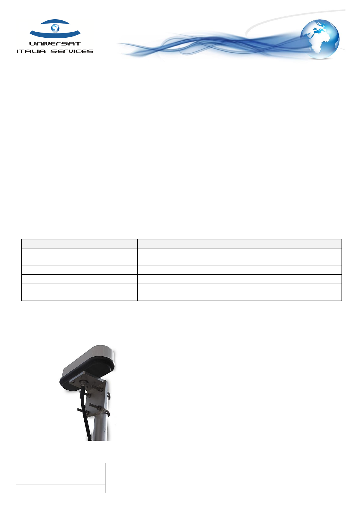
Universat Italia Services AD511-2 User manual

AD11-2 Iridium Active Antenna
Iridium Accessories Product Sheet
Universat Italia Services Srl
Viale Luca Gaurico, 9/11 (3rd floor) –00143 Roma –Italy - C.F./P.Iva 10191231009
Tel.: +39 06 5814292 - Fax: +39 06 54834000 –info@universatitalia.it –www.universatitalia.it
P a g i n a | 1
Enhancing Your
Connectivity
with Universat Italia Services
G L OB AL SA T EL L I TE C OM MU NI C AT I ON S
Iridium Antenna
Iridium Active Antenna AD511-2
The new AD-511-2 replaces the older series AD511, AD520-10 & AD510-10 models
Thisactive antenna allows Iridium users requiring an installation with long
cable runs to use a lower-grade, more-flexible cable. Ideal for most cable
runs between 27 meters and 160 meters. These extended cable lengths
offer the ability to provide Iridium installations on ships and land where
previously an Iridium solution could not operate.
AD-511-2 Iridium Active Antenna is designed to allow Iridium installations
with up to 160 meters of coaxial RF cable, without any degradation of
performance, compared to only 30 meters maximum for a standard
passive antenna device.
High Quality Active AD511-2 Antenna
Extremely rugged and reliable, the Iridium Active Antenna AD-511 is backed by an exclusive three
(3) year manufacturer’s warranty. It is manufactured from anodized hard aluminum and pressure
molded GRP radome providing a sealed, dust and water-resistant antenna.
AD-511-2 Iridium Active Antenna is supplied without coaxial cable as standard but allows pre-set
lengths between 27 and 160 meters subject to use of the correct, Universat identified coaxial cable
(Main antenna coax cable not included). Note: use of the incorrect cable at the specified length or
shortening of a cable can damage the antenna and invalidate the warranty.
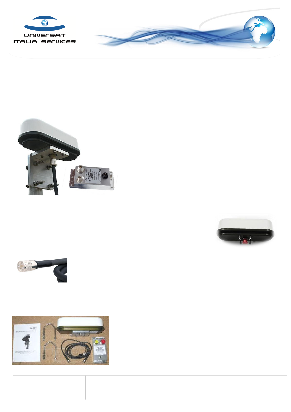
Box Contents for the Active Iridium Antenna AD511-2
►Iridium Active Antenna (AD511-2):
includes- heavy duty alloy mounting bracket, DC leads, Power Break-In Box and 0.5 m coaxial
cable w/TNC M TNC M end connectors.
►AD511-3 Power Break-In Box:
this is designed to sit close to the Iridium phone device and requires a DC power input
between +18V to +36V DC at 500mA (Power supply not included). A 0.5-meter coaxial lead is
supplied to connect the Iridium phone device to the Power Break-In Box.Iridium Active
Antenna (AD511-2): includes- heavy duty alloy mounting bracket, DC leads, Power Break-In
Box and 0.5 m coaxial cable w/TNC M TNC M end connectors.

AD11-2 Iridium Active Antenna
Iridium Accessories Product Sheet
Universat Italia Services Srl
Viale Luca Gaurico, 9/11 (3rd floor) –00143 Roma –Italy - C.F./P.Iva 10191231009
Tel.: +39 06 5814292 - Fax: +39 06 54834000 –info@universatitalia.it –www.universatitalia.it
P a g i n a | 2
Enhancing Your
Connectivity
with Universat Italia Services
G L OB AL S A T EL L I TE C OM MU NI C AT I ON S
AD511-2 Active Iridium Antenna User Manual
FEBRUARY 2018 | V2.0
TABLE OF CONTENTS
1. FCC APPROVAL
3
1.1. FCC 15.19 (A) (3)
3
1.2. FCC 15.105 (B)
3
1.3. ICES-003
3
1.4. USER MANUAL NOTICE FOR LICENSE-EXEMPT RADIO
APPARATUS
3
2. INTRODUCTION
(incl. AD511 Iridium Active Antenna Cable options)
4
3. MOUNTING AND OPERATION
5
4. FIGURES
6

AD11-2 Iridium Active Antenna
Iridium Accessories Product Sheet
Universat Italia Services Srl
Viale Luca Gaurico, 9/11 (3rd floor) –00143 Roma –Italy - C.F./P.Iva 10191231009
Tel.: +39 06 5814292 - Fax: +39 06 54834000 –info@universatitalia.it –www.universatitalia.it
P a g i n a | 3
Enhancing Your
Connectivity
with Universat Italia Services
G L OB AL S A T EL L I TE C OM MU NI C AT I ON S
1. FCC Approval
_____________
1.1. FCC 15.19 (a) (3)
This device complies with Part 15 of the FCC Rules. Operation is subject to the following two conditions: -
1. This device may not cause interference,and
2. This device must accept any interference, including interference that may cause undesired operation of the device.
1.2. FCC 15.105 (b)
The equipment has been tested and found to comply with the limits for a Class B device, pursuant to Part 15 of the FCC Rules. These limits are
designed to provide reasonable protection against harmful interference in a residential installation.
This equipment generates, uses, and can radiate radio frequency energy and, if not installed and used in accordance with the instructions, may cause
harmful interference to radio communications. However, there is no guarantee that interference will not occur in a particular installation. If this
equipment does cause harmful interference to radio or television reception, which can be determined by turning the equipment off and on, the user
is encouraged to try to correct the interference by one or more of the following measures: -
•Reorient or relocate the receiving antenna.
•Increase the separation between the equipment andreceiver.
•Connect the equipment into an outlet on a circuit different from that to which the receiver is connected.
•Consult the dealer or an experienced radio/TV technician forhelp.
1.3. ICES-003
This Class B digital apparatus complies with Canadian ICES-003.
1.4. User Manual Notice for License-Exempt Radio Apparatus
This device complies with Industry Canada license-exempt RSS Standard(s). Operation is subject to the following two conditions: -
1. This device may not cause interference,and
2. This device must accept any interference, including interference that may cause undesired operation of the device

AD11-2 Iridium Active Antenna
Iridium Accessories Product Sheet
Universat Italia Services Srl
Viale Luca Gaurico, 9/11 (3rd floor) –00143 Roma –Italy - C.F./P.Iva 10191231009
Tel.: +39 06 5814292 - Fax: +39 06 54834000 –info@universatitalia.it –www.universatitalia.it
P a g i n a | 4
Enhancing Your
Connectivity
with Universat Italia Services
G L OB AL S A T EL L I TE C OM M U NI C AT I ON S
2. Introduction
____________
Iridium telephones were originally designed to operate with a passive antenna, either an element attached directly to the handset, or a remote aerial
connected with a short length of coaxial cable. Unfortunately, a signal loss of more than 3dB in a remote antenna’s connecting cable degrades
performance due to attenuation of both the received and transmitted signals. A 3dB loss corresponds to approximately 10m of RG213U or 3m of
RG58U coaxial cable, lengths that clearly restrict the mounting options for the antenna using standard down-leads.
AD511-2 active Iridium antenna (figure 1 & figure 2) is designed for use with up to 160 meters of coaxial cable terminated with type ‘N’ connectors,
and with coax lengths starting from 27meters –subject to AST advice.
AD511 Iridium Active Antenna Cable
The AD511 Cable is customized specifically for the AD511 Iridium Active Antenna. The use of the incorrect cable can damage the antenna to the
point that cannot operate anymore and will also invalidate the manufacturer’s warranty. It is highly recommended to use the AD511 custom antenna
cable to avoid any possible damage to the antenna. We carry a variety of different sizes of cable for any type of installation.
TYPE
SIZE
AD511-27M
27m Antenna Cable for use with AD511 N-N
AD511-40M
40m Antenna Cable for use with AD511 N-N
AD511-64M
64m Antenna Cable for use with AD511 N-N
AD511-80M
80m Antenna Cable for use with AD511 N-N
AD511-120M
120m Antenna Cable for use with AD511 N-N
AD511-162M
162m Antenna Cable for use with AD511 N-N
Designed for harshenvironments, the AD511-2 consists oftwo RHCP dipole antenna housed within a 4mm thick GRP radome mounted on a common
base. One antenna is for signal transmission and one for reception.
AD511-2 has a linear power amplifier within the base and connected to
the transmitting antenna compensates for signal loss incurred mainly by
the connecting cable. Similarly, a low noise amplifier is attached to the
receiving antenna via a low loss interdigital filter to boost the signal sent
to the telephone. The interdigital filter has a bandwidth of 25 MHz
centered on the Iridium band designed to attenuate any out of band
interference that may arise, for example from nearby Inmarsat uplinks.
Using manufacturing techniques proven for a range of extremely rugged
GPS/DGP active antenna, the base is milled from aluminium and hard
anodised, giving an attractive grey finish, which is mechanically resilient
and resistant to corrosion. The antenna’s mass is 0.8kg.

AD11-2 Iridium Active Antenna
Iridium Accessories Product Sheet
Universat Italia Services Srl
Viale Luca Gaurico, 9/11 (3rd floor) –00143 Roma –Italy - C.F./P.Iva 10191231009
Tel.: +39 06 5814292 - Fax: +39 06 54834000 –info@universatitalia.it –www.universatitalia.it
P a g i n a | 5
Enhancing Your
Connectivity
with Universat Italia Services
G L OB AL S A T EL L I TE C OM M U NI C AT I ON S
3. Mounting and Operation
_______________________
AD511-2 should be mounted with an unobstructed view of the sky. An aluminium bracket with V-bolts is provided to attach the antenna to horizontal
or vertical masts or spars up to 50mm in diameter, figure 2. The bracket is shipped inverted at the centre of the AD511-2 antenna and should be
detached, inverted, then reattached to antenna case using the mounting holes in the base.
The coaxial down-lead is attached to the N-type connector on the underside of the antenna, figure 2. Wrapping the connectors with self-
amalgamating tape is recommended for permanent installations and the cable should be taped or strapped to the spar as appropriate.
►AD511-2 antenna supplied with coaxial down-leads must be used with the accompanying AD511-3 DC Power Break-In Box (figure 3), which
accepts +18V to +36V DC at 500mA. The down-lead must not be shortened by the user.
AD511-3 Power Break-In should be positioned close to the telephone base- station or handset. The coaxial down-lead is then attached to the N type
connector on the AD511-3 (figure 3 & figure 4). Earthing: - the AD-511-3 power breaking box is provided with an earth terminal. The box should be
earthed via this connection with a short earthing lead connection to the system earth.
Connection between the telephone and the AD511-3 is made with a coaxial cable terminated with TNC connectors. An adapter is provided with the
Iridium handset, which enables a TNC terminated cable to be attached to the telephone. AD511-3 case has drilled flanges to enable permanent
fixing.
A 1m flying lead for the AD511-3 Power Break-In Box is provided for connection to the DC supply (+18 to 36 v DC at 500mA), which can be trimmed
(or extended) if necessary. The red wire is connected to supply positive, whilst the blue wire is for either an isolated or grounded negative supply.
AD511-3 is protected against output short-circuiting by a fuse, which is resettable by disconnecting the unit from the +18 to +36 v DC supply.
With all connections made, the telephone can then be turned on and used as normal - it is transmitting into a load impedance equivalent to a
matched passive antenna. The gains of the antenna transmitter and receiver are factory set to compensate for the total attenuation between the
telephone and the antenna, mainly determined by the coaxial down-lead. Consequently, the signal output level and frequency from the antenna is
equivalent to that radiating from a passive antenna mounted directly on the handset, subject to the antenna transmitter being a linear device.
Transmitter linearity is verified with test protocols using an HP 8591 EMC analyser that also ensure there are no spurious out of band emissions
Not Included / Optional:
Iridium Active Antenna
Cable
Power supply +18V to +36V
DC at 500mA

AD11-2 Iridium Active Antenna
Iridium Accessories Product Sheet
Universat Italia Services Srl
Viale Luca Gaurico, 9/11 (3rd floor) –00143 Roma –Italy - C.F./P.Iva 10191231009
Tel.: +39 06 5814292 - Fax: +39 06 54834000 –info@universatitalia.it –www.universatitalia.it
P a g i n a | 6
Enhancing Your
Connectivity
with Universat Italia Services
G L OB AL S A T EL L I TE C OM M U NI C AT I ON S
4. Figures
____________
Figure 1. AD511-2 Active Iridium antenna
Ù
Figure 2. AD511-2 with mounting bracket and coaxial down-lead
Figure 3. AD511-3 Power Break-In Box for use with +18 to +36 v DC supply
Figure 3. AD511 Schematic diagram for system connection
The case is hard anodised aluminium and has fixing flanges. A 40m coil of
RG213U cable is shown connected to an AD511-2 active antenna (top). The
handset interconnect is shown trailing from the TNC to the bottom left,
whilst the flying lead for connection to 18 to 36 v DC supply is shown cutting
the frame to the left.
Mount AD511-2 with clear view of sky using bracket supplied.
Attach top end of coax down-lead to N type connector on underside of
antenna.
Attach bottom end of down-lead to N type connector to the Power
Break-In Box AD511-3. The down-lead must not be shortened.
Attach interconnect between TNC on AD510-40 and telephone (or base
station) using the antenna adapter provided with the phone.
Attach DC supply lead to +18 to +36 v DC supply (600mA max). Red lead
to +supply, Blue to –supply.
Turn on Iridium telephone and log-in.
The AD511-2 should only be used with the AD511-3 Break-In Box. It is
not to be used with AD511 or AD510-40 Break-In Boxes.
Table of contents
Other Universat Italia Services Antenna manuals
Popular Antenna manuals by other brands

THOMSON
THOMSON ANT1608 operating instructions

APM
APM APG-251215 Specification sheet

Panorama Antennas
Panorama Antennas SW3-091 - v2 instructions

Matchmaster
Matchmaster Digimatch Explorer 01MM-DE7 installation instructions

DBK
DBK LWM-326 WS Operation manual

Maxview
Maxview Precision I.D MXL019/55 User operating instructions

Novatel
Novatel GPS-302-40 user guide

TERK Technologies
TERK Technologies XM6 owner's manual

Kathrein
Kathrein HDS 166 Guide

Hirschmann Car Communication
Hirschmann Car Communication AUTA 4000 F 317 L installation instructions

Hollyland
Hollyland Panel Antenna user manual

Mobiltech
Mobiltech MOBILSAT 2016 DISMOUNT MANUAL