Fitting and using the 3 point double inertia occupant restraint
Fit and use
Rail floor
1. The rail will have been installed in the vehicle in accordance with their own and the vehicle
converter’s instruction. Position wheelchair within vehicle as required.
2. Wheelchair tie-downs (not supplied with these restraints) should be fitted first to secure
the wheelchair, before any occupant restraint is fitted.
3. Position the occupant restraint behind the wheelchair tie-down, with reel housing (Fig. 1A)
on the window side of the vehicle and reversible/fixed stalk (Fig.1B) on the aisle side.
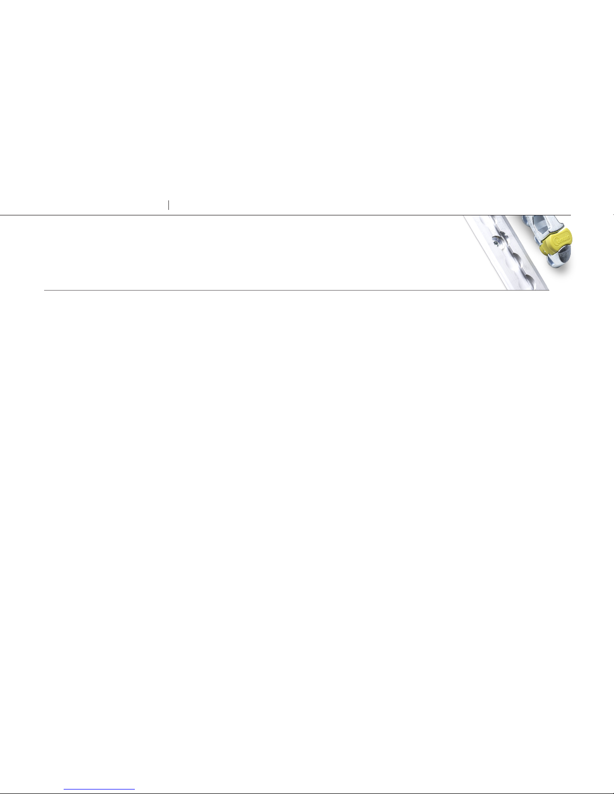
4. Fit the occupant restraint ATF (aluminium track fitting) into the rail by aligning the ATF feet
with the cut-out sections of the rail. Locate into the rail, (Fig 2).
5. Press on the ribbed part of the ATF, (Fig 2A), and push firmly towards the wheelchair until
the yellow plunger drops and locks into the rail.
6. Position the third point fixing into the cant rail (Fig 3) so that it is vertically above the inertia
reel casing fixed onto the floor fixing. Unfasten the tongue and buckle.
7. Pull the webbing upwards and unfasten the tongue from the grey webbing buckle.
8. Position the black webbing to form the lap belt and insert the tongue into the buckle stalk.
Ensure that the lap belt lays low on the pelvis of the occupant, running as close as possible
over the hips on both sides.
9. Remove the black plastic cover on the grey shoulder belt tongue and fit into the third
point fixing. Position the grey webbing to form the shoulder belt and insert the buckle
into the tongue. Adjust the height of the shoulder belt to clear the occupant’s shoulder by
approximately 25mm (1 inch) Fig 4.
10. The lap belt anchor points should be positioned to achieve belt angles of 30° or more to
the horizontal and preferably between 45° and 75° in order to fit low across the pelvis
reducing the possibility of the belt loading the abdomen (Fig 5). The pelvic restraint is
designed to bear upon the bony structure of the body and should be worn low across the
front of the pelvis with any junctions between the pelvic and shoulder restraints located
near the wearers hips.
Removing occupant restraints
1. Release the grey shoulder belt from
the lap belt section, then from the
third point fixing and carefully allow the
shoulder belt to return to the retractor.
2. Disconnect the black lap belt from
the buckle stalk on the aisle side and
carefully allow the lap belt webbing to
return onto it’s retractor.
3. Connect the shoulder belt buckle to the
lap belt tongue above the opening of
the retractor box.
4. The wheelchair tie-down must now be
removed.
10 Wheelchair & Occupant Restraints Occupant Restraints