Unwin DI-RQMK User manual

EN Instructions for fitting and use
Combined Retractable Tie-downs
with 2 & 3 Point Occupant Restraints
Unwin User Manual

2Combined retractable tie-downs with 2 & 3 point occupant restraints Wheelchair & occupant restraint
The following manual is an important part of the product, providing you with
information on how to achieve maximum performance and safe operation.
Keep the manual in a safe place so that you can refer to it when necessary.
If you have any questions about your equipment, please contact Unwin.
Once again, thank you for placing your confidence in our products!
Unwin
Thank you for choosing
Safe vehicle adaptation solutions
For your safety Unwin products are
designed and tested according to current
directives and standards.
Combined Retractable Tie-downs
with 2 & 3 Point Occupant Restraints!
S
A
F
E
V
E
H
I
C
L
E
A
D
A
P
T
A
T
I
O
N

Safety information
4
6
8
Fit and use
10-25
10
16
18
20
22
24
After care
26
26
Limitations of use
General guidance
Before installing and using the combined retractable tie-downs with 2 & 3 point occupant restraints
Fitting & using the combined retractable tie-downs with 2 & 3 point occupant restraints
Combined retractable tie-downs with 2 & 3 point double inertia - rail floor
Combined self-retracting tie-downs with 2 & 3 point double inertia - rail floor
Combined retractable tie-downs with 2 & 3 point double inertia - floor anchor
Combined self-retracting tie-downs with 2 & 3 point double inertia - floor anchor
Combined retractable & sef-retracting tie-downs with 3 point static occupant restraint - floor anchor
Combined retractable & self-retracting tie-downs & 3 point WAV retractable occupant restraint - floor anchor
Equipment storage and maintenance
Warranty
3
Wheelchair & occupant restraint Combined retractable tie-downs with 2 & 3 point occupant restraints
EN
Index
“Declaration of conformity” at the end of the manual.

Limitation of use
Safety information
The development of Unwin wheelchair combined wheelchair & occupant restraints
is a continuous process. Applications are added on a regular basis. For more detail
contact Unwin or look on the Unwin website.
4Combined retractable tie-downs with 2 & 3 point occupant restraints Wheelchair & occupant restraint

Combined webbing tie-down with 2 & 3 point occupant restraint
DI-RQMK DK-SQEPH
STK-SQMH WK-SQEPH
DI-RQEPT
5
Wheelchair & occupant restraint Combined retractable tie-downs with 2 & 3 point occupant restraints
EN
Safety information

General guidance
• Wheelchair Accessories that have not been approved by the Wheelchair Manufacturer must be
removed from the wheelchair and secured in the vehicle during transport to reduce the potential for
injury. Refer to ‘Instructions For Use in Transport’ provided with the wheelchair or contact wheelchair
manufacturer for further guidance.
• These combined wheelchair & occupant restraints comply with all applicable requirements of ISO 10542,
including a 48km/h, 20g frontal impact test using a forward facing 85kg surrogate wheelchair and an ATD
(test dummy) with a mass of 76.3kg. The test dummy was restrained by both a pelvic and upper-torso
restraint. Use of a pelvic only belt may compromise the performance of the WTORS system and should
be avoided.
• If the installation is to be used with an occupant head rest anchored to the vehicle, then a vehicle-
anchored back rest must be provided to minimise rearward deflection of the wheelchair seatback,
preventing neck injury.
• Regular inspection of all parts is recommended and the equipment should be used only if all
components are in good condition.
• Warning: protect webbing from contacting sharp edges and corners. Replace equipment if the
webbing does becomes cut, contaminated or frayed.
6Combined retractable tie-downs with 2 & 3 point occupant restraints Wheelchair & occupant restraint

• Any wheelchair & occupant restraints which have been subjected to a crash situation from which the
vehicle must be towed should, in the interest of safety, be replaced.
• Do not attempt to modify the equipment. For further advice on the installation and use of this
wheelchair & occupant restraint, please contact Unwin. Please read this manual fully before use.
• Avoid contact with corrosive liquids. Care should be taken to prevent contamination of the webbing
with polishes, oils and chemicals.
• The wheelchair & occupant restraint anchorages should be installed by an experienced technician/vehicle
converter. Anchorages should not be installed into unsound materials such as corroded metal, wood,
plastic and fibre glass panels, without additional and suitable reinforcement.
• The equipment has been tested in a configuration similar to that recommended by Unwin, and any
deviation from the recommendations here is the responsibility of the installer/user. These instructions
refer use with both Unwin rails and Solo anchors, however the equipment may be used with any Unwin
proprietary rail product.
7
Wheelchair & occupant restraint Combined retractable tie-downs with 2 & 3 point occupant restraints
EN
Safety information

Before installing and using the combined wheelchair & occupant restraint
• Ensure that the wheelchair is correctly maintained and that the settings of any adjustable parts are made
according to ‘Instructions for Use in Transport’.
• Whenever possible remove any items of luggage etc that may be attached to the wheelchair and secure
or store separately during transport in order to reduce the potential for injury to other passengers
travelling in the vehicle.
• Extra care must be exercised when using vehicle boarding aids such as passenger lifts or ramps during
the loading process. Refer to ‘Instructions For Use’ for information on safe slopes.
• Position the wheelchair facing forward - centrally in the designated region of the vehicle. Ensure the
wheelchair brakes are applied.
• To minimise the potential for head injuries in an impact, allow a clear space of at least 400 mm behind
and 650 mm, (FCZ, front clear zone), in front of the head of the wheelchair user, (Fig A). The shoulder
belt anchorage must be roof or side-wall anchored at a height level such that the belt webbing passes
over the midpoint of the occupant shoulder and at a height that is at or just above the level of the
occupants shoulders so as not to impose downward loads on the spine.
• A height provision (HHT) ranging from 1000mm to 1550mm should be made, depending on the size
of the passenger. There should also be 200 mm of clear space either side of the wheelchair centre line.
If these clear space dimensions cannot be provided then any should be adequately padded and comply
with impact performance requirements of ECE Regulation 21 ‘FMVSS 201’. All vehicle padding should
comply with the flammability require ments of ECE Regulation 118 ‘FMVSS 302’.
Note: seated head
height (HHT)
ranges from as low
as 1000mm for a
6-year-old child to
1550mm for a tall
adult.
8Combined retractable tie-downs with 2 & 3 point occupant restraints Wheelchair & occupant restraint

• Wheelchair users, their carers and family are advised to check vehicle
specifications to ensure that sucient floor space is available to accommodate
the wheelchair and tie-down system. These distances are based upon the desire
to maintain clear zones for potential head excursions of occupants provided with
both upper and lower torso restraints.
• Users of heavy powered wheelchairs are also advised to check vehicle carrying
capacity. If in doubt consult the vehicle supplier for further details.
• Any airbag, as fitted to the vehicle, shall be used only as a supplementary
occupant restraint if designed to be used in combination with the Solar Quattro
and an appropriate occupant restraint.
• Installers of this wheelchair & occupant restraint should take note of any vehicle
airbag position when planning the installation. Airbags can cause serious injury if
a wheelchair-seated occupant is seated too close to an airbag position. If in doubt
contact the vehicle manufacturer or your National Automotive Regulatory Body
for advice.
Figure A
9
Wheelchair & occupant restraint Combined retractable tie-downs with 2 & 3 point occupant restraints
EN
Safety information

Fitting and using the combined retractable tie-down with 2 & 3 point
double inertia
Fit and use
Rail floor Wheelchair Tie-down:
1. The rail will have been installed in the vehicle in accordance with
their own and the vehicle converter’s instruction. Position the
wheelchair within the vehicle as required.
2. Attach the front wheelchair tie-down (not supplied as part of
this product) in accordance with its own instruction.
3. Place the combined rear retractable restraint into the rail behind
the wheelchair. It is acceptable to use the restraint either for left
hand or right hand use. The double inertia reel should be fitted
to the rail adjacent to the 3rd point anchorage.
4. Moving to the wheelchair rear, select rear retractable tie-down
so that the karabiner or hook gates face outboard from the
wheelchair, (Fig 1). If using tongue & buckle, the buckle may be
positioned facing inboard or outboard,
(Fig 2).
5. Attach each tie-down into the floor rail by aligning the ATF
(aluminium track fitting) feet with the cut-out sections of the rail,
(Fig 3). Note: the yellow plungers must face toward the rear of
the vehicle. Press down on the ribbed part of the ATF, (Fig 3A),
and push firmly down towards the wheelchair until the yellow
plunger drops and locks into the rail.
6. Press the yellow Quattro release button(s), (Fig 4A) to extend
the webbing and attach the karabiner(s), hook(s) or tongue and
buckle arrangement(s) around the wheelchair main frame. Some
wheelchairs will indicate this rear frame tie-down position, (Fig 5).
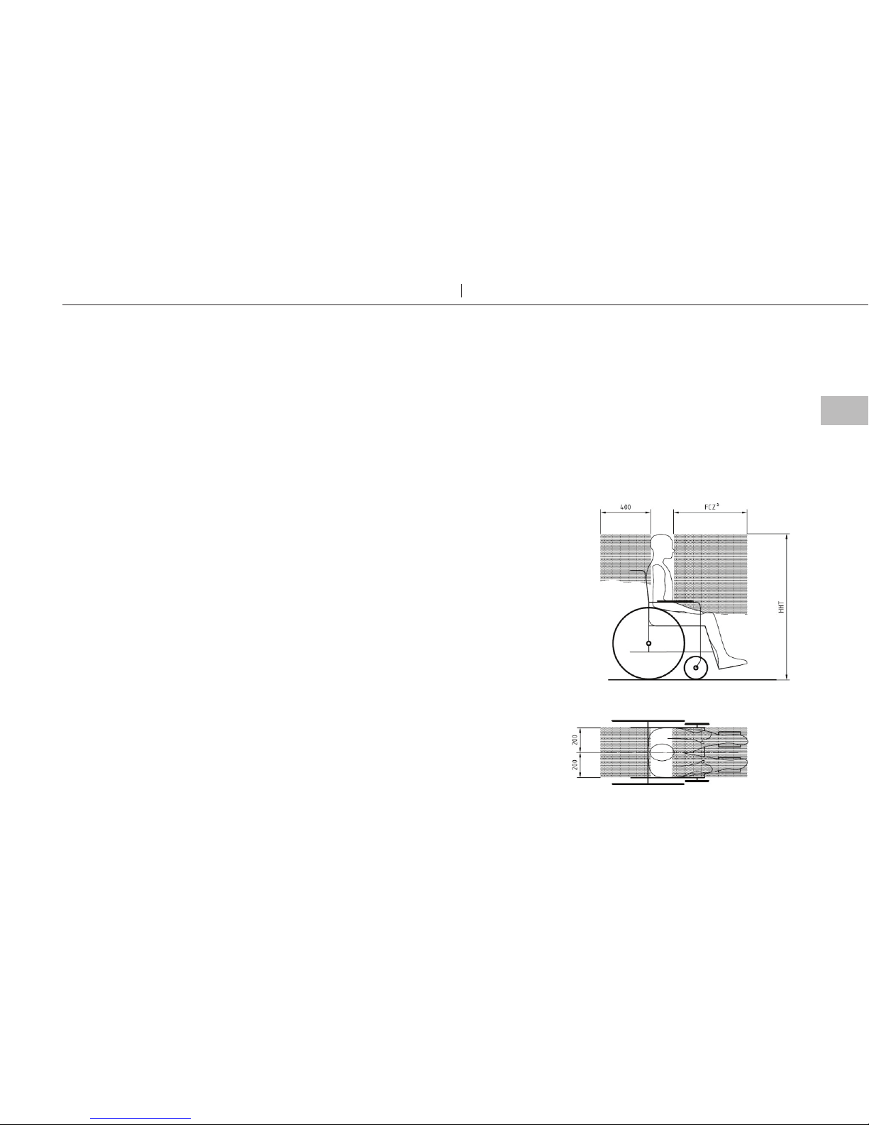
7. Press each Quattro release button once again to take up the slack in
the webbing and create an angle of around 30 to 45° and within the
rear view zone, (Fig 6).
8. Final tensioning is achieved by turning each tensioning handle,
(Fig 4B), until the webbing is equally taut on each side.
9. The occupant restraint must now be fitted.
Removing wheelchair tie-down
1. Release the tension in the rears by pressing the yellow button and
extend the webbing to allow the karabiner(s) / hook(s)/tongue &
buckles(s) to be removed from the wheelchair frame. If the webbing
is particularly tight, it may be necessary to slightly 'tension' with the
hand wheel whilst pressing the yellow button, in order to remove
the webbing lock on the Quattro.
2. Lift the yellow plunger fully, slide back away from the wheelchair to
align the ATF feet with the rail cut outs, lift away from the rail and
store securely.
10 Combined retractable tie-downs with 2 & 3 point occupant restraints Wheelchair & occupant restraint

Figure 5
Figure 1 Figure 2
Figure 6
Figure 3
A
Figure 4
A
B
11
Wheelchair & occupant restraint Combined retractable tie-downs with 2 & 3 point occupant restraints
EN
Fit and use

Fitting and using the combined retractable tie-down with 2 & 3 point double inertia
Fit and use
Rail Floor 3 point double inertia seatbelt
• Unwin recommends the use of a 3 point occupant restraint system to provide greater protection in case of an impact. However we
also recognise that some vehicle layout/designs or specific postural or medical conditions do not allow that style of seatbelts to be
used easily.
• This system is not ISO 10542 compliant if used in 2 point configuration.
• Before fitting the occupant restraint, ensure that the reversible or fixed stalk button is facing outside in relation to the wheelchair.
With the reversible stalk, if orange button faces inside, turn the stalk 180º to sit in the right position.
• In accordance with International regulations, standard Unwin occupant restraints are designed to be used for passengers weighing
22kg or above. If the passenger weighs less than 22kg, Unwin recommend that a suitable, and appropriately tested child restraint
seat is used. This may involve a secondary seat belt restraint as recommended by the original seat manufacturer.
1. Position the third point fixing into the cant rail, (Fig 7), so that it is vertically above the inertia reel
casing fixed onto the floor fixing. Unfasten the tongue and buckle.
2. Pull the black webbing upwards and unfasten the tongue from the grey webbing buckle.
3. Position the black webbing to form the lap belt and insert the tongue into the buckle stalk, (Fig 8).
4. Ensure that the lap belt lays low on the pelvis of the occupant, running as close as possible over
the hips on both sides.
5. Remove the black plastic cover on the grey shoulder belt tongue and fit into the third point fixing.
6. Position the grey webbing to form the shoulder belt and insert the buckle into the tongue.
7. Adjust the height of the shoulder belt to clear the occupant’s shoulder by approximately 25mm -
1 inch, (Fig 9).
8. The lap belt anchor points should be positioned to achieve belt angles of 30° or more to the
horizontal and preferably between 45° and 75° in order to fit low across the pelvis reducing the
possibility of the belt loading the abdomen, (Fig 10). The pelvic restraint is designed to bear upon
the bony structure of the body and should be worn low across the front of the pelvis with any
junctions between the pelvic and shoulder restraints located near the wearers hips.
Removing occupant restraint
1. Release the grey shoulder belt from
the lap belt section, then from the
third point fixing and carefully allow
the shoulder belt to return to the
retractor.
2. Disconnect the black lap belt from
the buckle stalk on the aisle side and
carefully allow the lap belt webbing
to return onto it’s retractor.
3. Connect the shoulder belt buckle
to the lap belt tongue above the
opening of the retractor box.
4. The wheelchair tie-down should
now be removed.
12 Combined retractable tie-downs with 2 & 3 point occupant restraints Wheelchair & occupant restraint

Figure 8 Figure 10
Figure 9 Figure 7
13
Wheelchair & occupant restraint Combined retractable tie-downs with 2 & 3 point occupant restraints
EN
Fit and use

Fitting and using the combined retractable tie-down with 2 & 3 point double inertia
Fit and use
1. Ensure the Comfort Clip is released (Fig 12) and press the buckle to release the lap belt.
2. Pull the metal tongue on the black webbing upwards to release the webbing from both
inertia reels. Position the webbing across the occupant with the black webbing forming
the lap belt and the grey webbing forming the shoulder belt (Fig 13).
3. Insert the tongue fixed to the black webbing into the stalk buckle (11A).
4. Adjust for comfort by raising the webbing on the shoulder by two finger widths, unlock
the Comfort Clip to take up the slack, then re-lock the clip so that it rests on the reel
cover.
5. The lap belt anchor points should be positioned to achieve belt angles of 30° or more to
the horizontal and preferably between 45° and 75° in order to fit low across the pelvis
reducing the possibility of the belt loading the abdomen (Fig 10). The pelvic restraint is
designed to bear upon the bony structure of the body and should be worn low across
the front of the pelvis with any junctions between the pelvic and shoulder restraints
located near the wearers hips.
Removing occupant restraint
1. Release the Comfort Clip.
2. Release the grey shoulder belt from the
lap belt section, and carefully allow the
shoulder belt to return to the retractor.
Disconnect the black lap belt from
the buckle stalk on the aisle side and
carefully allow the lap belt webbing to
return onto it’s retractor.
3. Connect the shoulder belt buckle to the
lap belt tongue above the opening of
the retractor box.
4. The wheelchair tie-down should now
be removed.
Rail Floor 2 point double inertia seatbelt
14 Combined retractable tie-downs with 2 & 3 point occupant restraints Wheelchair & occupant restraint

Figure 3
A
Figure 10
Figure 12
Figure 13
Fi g ur e 11
A
A
15
Wheelchair & occupant restraint Combined retractable tie-downs with 2 & 3 point occupant restraints
EN
Fit and use

Fitting and using the combined self-retracting tie-down with 2 & 3 point
double inertia
Fit and use
1. The rail will have been installed in the vehicle in accordance with their own and the
vehicle converter’s instruction. Position wheelchair within vehicle as required.
2. Place the combined rear webbing restraint into the rail behind the wheelchair. It is
acceptable to use the restraint either for left hand or right hand use. The double inertia
reel should be fitted to the rail adjacent to the 3rd point anchorage.
3. Moving to the wheelchair rear, select the combined wheelchair and occupant restraint
so that the karabiner or hook gates face outboard from the wheelchair, (Fig 1). If using
tongue & buckle, the buckle may be positioned facing inboard or outboard, (Fig 2).
Attach each restraint into the floor rail by aligning the ATF (aluminium track fitting) feet
with the cut-out sections of the rail, (Fig 3). Note: the yellow plungers must face toward
the rear of the vehicle. Press down on the ribbed part of the ATF, (Fig 3A), and push
firmly down towards the wheelchair until the yellow plunger drops and locks into the rail.
4. Note: It is not necessary to press yellow button. Webbing can be extended from the
reel without pressing the yellow button if the lock label, (Fig 15), is NOT visible. The
yellow button must be pressed if extending webbing with the label in view.
5. Slack in the webbing with be taken in automatically by the reel to create an angle of
around 30 to 45° and within the rear view zone, (Fig 6).
6. Final tensioning is achieved by turning each tensioning handle (Fig. 14B) until the webbing
is equally taut on each side. The webbing with retract automatically into the reel.
IMPORTANT: The yellow locking label must be fully visible, to ensure that the reel is
locked o, (Fig 15).
7. Ensure that each rear Quattro Express webbing is approximately of the same length.
8. The occupant restraint must now be fitted - refer to pages 12-15.
Removing wheelchair tie-down
1. Release the tension in the rears by
pressing the yellow button,
(Fig 14A), and extend the webbing
to allow the karabiner(s)/hook(s) or
tongue & buckles to be removed from
the wheelchair frame. If the webbing is
particularly tight, it may be necessary to
slightly 'tension' with the hand wheel,
(Fig 14B), whilst pressing the yellow
button, in order to remove the webbing
lock on the Quattro Express.
2. Remove each Quattro Express ATF
from the rail by simultaneously lifting
the yellow plunger and sliding the fitting
back until the ATF feet align with cut
outs in the rail.
3. Lift the Quattro Express away from the
rail and store securely.
Rail floor Wheelchair Tie-down:
16 Combined retractable tie-downs with 2 & 3 point occupant restraints Wheelchair & occupant restraint

Figure 15
Figure 14
A
B
Figure 1 Figure 2
Figure 3
A
Figure 5
Figure 6
17
Wheelchair & occupant restraint Combined retractable tie-downs with 2 & 3 point occupant restraints
EN
Fit and use

1. The Solo anchors will have been installed in the vehicle in accordance with our own and
the vehicle converters instruction. A front wheelchair should be secured first, before any
rear combined restraints are fitted.
2. Place the combined rear retractable restraint into the floor anchor behind the
wheelchair. It is acceptable to use the restraint either for left hand or right hand use. The
double inertia reel should be fitted to the rail adjacent to the 3rd point anchorage.
Ensure that the combined wheelchair and occupant restraint is fitted with the karabiner /
hook gates facing outwards, the same way as the fronts.
3. Install the restraint(s) onto the floor anchors by aligning the protrusion within each cleat
to the slot on the floor anchors.
4. Slide the cleat fully home, (Fig 17), rotate the assemblies through 90°. to allow the
karabiners or hooks to be attached to the wheelchair frame.
5. Press the yellow Quattro release button(s), (Fig 18A), to extend the webbing and attach
the karabiner(s) or hook(s) around the wheelchair main frame. Some wheelchairs will
indicate this rear frame tie-down position, (Fig 5).
6. Press each Quattro release button once again to take up the slack in the webbing and
create an angle of around 30 to 45° and within the rear view zone, (Fig 6).
7. Final tensioning is achieved by turning each tensioning handle, (Fig 18B), until the webbing
is equally taut on each side.
8. The occupant restraint must now be fitted - refer to pages 12-15.
Removing wheelchair tie-down
1. Release the tension in the rears by
pressing the yellow button and extend
the webbing to allow the karabiner(s)/
hooks to be removed from the
wheelchair frame. If the webbing is
particularly tight, it may be necessary
to slightly 'tension' with the hand wheel
whilst pressing the yellow button, in
order to remove the webbing lock on
the Quattro.
2. Remove each Quattro Solo from
the anchor by rotating the tie-down
through 90° so that the raised protusion
on the cleat is aligned with the indent
on the floor anchors, (Fig 16). Slide o.
Note: protrusion and indent are only
applicable with spring loaded anchors,
not with static anchors S10.
3. Pull the tie-down away from the floor
anchor and store safely.
Fitting and using the combined retractable tie-down with 2 & 3 point
double inertia
Fit and use
Floor anchors Wheelchair Tie-down:
18 Combined retractable tie-downs with 2 & 3 point occupant restraints Wheelchair & occupant restraint

A
B
Figure 16
Indent
Protrusion
Figure 17
Figure 5
Figure 6
Figure 18
19
Wheelchair & occupant restraint Combined retractable tie-downs with 2 & 3 point occupant restraints
EN
Fit and use

Fitting and using the combined self-retracting tie-down with 2 & 3 point
double inertia
Fit and use
1. The Solo anchors will have been installed in the vehicle in accordance with our own and
the vehicle converters instruction. A front wheelchair should be secured first, before any
rear combined restraints are fitted.
2. Place the combined rear retractable restraint into the floor anchor behind the wheelchair.
It is acceptable to use the restraint either for left hand or right hand use. The double
inertia reel should be fitted to the rail adjacent to the 3rd point anchorage.
Ensure that the combined wheelchair and occupant restraint is fitted with the karabiner
/hook gates facing outwards, the same way as the fronts.
3. Install the restraint(s) onto the floor anchors by aligning the protrusion within each cleat
to the slot on the floor anchors. Slide the cleat fully home, (Fig 17), rotate the assemblies
through 90°. to allow the hooks or karabiners to be attached to the wheelchair frame.
4. Note: It is not necessary to press yellow button. Webbing can be extended from the
reel without pressing the yellow button if the lock label, (Fig 15), is NOT visible. The
yellow button must be pressed if extending webbing with the label in view.
5. Slack in the webbing with be taken in automatically by the reel to create an angle of
around 30 to 45° and within the rear view zone, (Fig 6).
6. Final tensioning is achieved by turning each tensioning handle (Fig. 19B) until the webbing
is equally taut on each side. The webbing with retract automatically into the reel.
IMPORTANT: The yellow locking label must be fully visible, to ensure that the reel is
locked o, (Fig 15).
7. Ensure that each rear Quattro Express Solo webbing is approximately of the same length.
8. The occupant restraint must now be fitted - refer to pages 12-15.
Removing wheelchair tie-down
1. Release the tension in the rears by
pressing the yellow button,
(Fig 14A), and extend the webbing to
allow the karabiner(s)/hook(s) to be
removed from the wheelchair frame.
If the webbing is particularly tight, it
may be necessary to slightly 'tension'
with the hand wheel, (Fig 14B), whilst
pressing the yellow button, in order
to remove the webbing lock on the
Quattro Express Solo.
2. Remove each Quattro Express Solo
from the anchor by rotating the tie-
down through 90° so that the raised
protusion on the cleat is aligned with
the indent on the floor anchors,
(Fig 16). Slide o. Note: protrusion and
indent are only applicable with spring
loaded anchors, not with static anchors
S10. Pull the tie-down away from the
floor anchor and store securely.
Floor anchors Wheelchair Tie-down:
20 Combined retractable tie-downs with 2 & 3 point occupant restraints Wheelchair & occupant restraint
This manual suits for next models
4
Table of contents
Other Unwin Wheelchair manuals
Popular Wheelchair manuals by other brands

Pride
Pride JAZZY Sport owner's manual

Otto Bock
Otto Bock Ventus Instructions for use

Invacare
Invacare Top End Terminator SS Owner's operator and maintenance manual

Kid-Man
Kid-Man 07-2580 user manual

Meyra
Meyra 2.322 operating manual

Ki Mobility
Ki Mobility Little Wawe Arc XP User instruction manual & warranty