manuals.online logo
Brands
  1. Home
  2. •
  3. Brands
  4. •
  5. Uotek
  6. •
  7. Switch
  8. •
  9. Uotek UT-1208H User manual

Uotek UT-1208H User manual

Popular Switch manuals by other brands

SMC Networks SMC6224M Technical specifications

SMC Networks

SMC Networks SMC6224M Technical specifications

Aeotec ZWA003-S operating manual

Aeotec

Aeotec ZWA003-S operating manual

TRENDnet TK-209i Quick installation guide

TRENDnet

TRENDnet TK-209i Quick installation guide

Planet FGSW-2022VHP user manual

Planet

Planet FGSW-2022VHP user manual

Avocent AutoView 2000  AV2000BC AV2000BC Installer/user guide

Avocent

Avocent AutoView 2000 AV2000BC AV2000BC Installer/user guide

Moxa Technologies PT-7728 Series user manual

Moxa Technologies

Moxa Technologies PT-7728 Series user manual

Intos Electronic inLine 35392I operating instructions

Intos Electronic

Intos Electronic inLine 35392I operating instructions

Cisco Catalyst 3560-X-24T Technical specifications

Cisco

Cisco Catalyst 3560-X-24T Technical specifications

Asante IntraCore IC3648 Specifications

Asante

Asante IntraCore IC3648 Specifications

Siemens SIRIUS 3SE7310-1AE Series Original operating instructions

Siemens

Siemens SIRIUS 3SE7310-1AE Series Original operating instructions

Edge-Core DCS520 quick start guide

Edge-Core

Edge-Core DCS520 quick start guide

RGBLE S00203 user manual

RGBLE

RGBLE S00203 user manual

Thrustmaster FLIGHT SIMULATOR X quick guide

Thrustmaster

Thrustmaster FLIGHT SIMULATOR X quick guide

Southwire SURGE GUARD 41390 RVC troubleshooting guide

Southwire

Southwire SURGE GUARD 41390 RVC troubleshooting guide

Buhler Nivotemp NT 61 Brief instructions

Buhler

Buhler Nivotemp NT 61 Brief instructions

Kramer VS-41HDCP user manual

Kramer

Kramer VS-41HDCP user manual

Techly IDATA AU-270 user manual

Techly

Techly IDATA AU-270 user manual

Belkin F1U109 user manual

Belkin

Belkin F1U109 user manual

manuals.online logo
manuals.online logoBrands
  • About & Mission
  • Contact us
  • Privacy Policy
  • Terms and Conditions

Copyright 2025 Manuals.Online. All Rights Reserved.

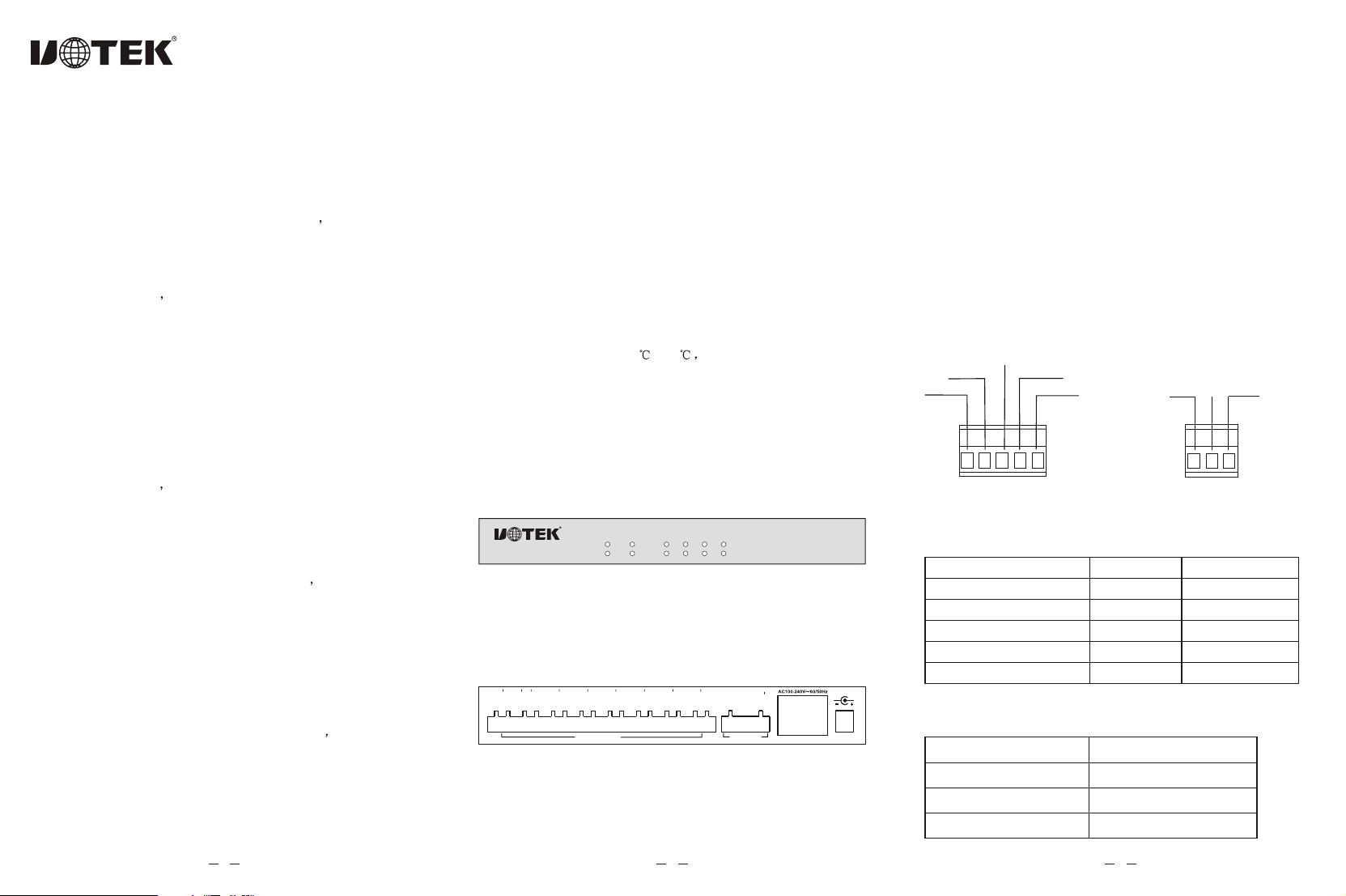
II. Panel andsignal indicators
There are 11 indicator lightson the frontpanel of UT-1208H,
and on theback panel there are 1 5-pinterminal for RS-485 or
RS-232 input and8 ports 3-pin terminals for photoelectrical
isolation input ports.
II. Parameters
1. Interface features:compatible with RS-232C and RS-485
standards of EIA/TIA.
2. Electric interface:RS-232C interface for the 1st -3rdpins
of the 5-PINterminals, and RS-485 interface
for the 4th 5th pins ofthe 5-PIN terminals.
3. Transmissionmedia: twisted-pair cable or shielded cable.
4. Working mode: asynchronoushalf-duplex.
5. Signal indication:12 signal indicator including power (PWR),
send(TXD), receive(RXD) andfailure(E1-E8).
6. Isolation degree:a isolation voltage of 2,500V RMS500VDC
non-stop and DC/DCisolation module.
7. Transmissionrate: 300BPS-115.2K.
8. Protection grade:RS-232 interface 15KVESD protection,
RS-485 interface 1,500Wlighting strike surge
protection for eachline.
9. Transmissiondistance: 0-5km (115,200-300BPS)
10.Measurements: 210mmX130mmX33mm
11.Workingenvironment: -40 to 80 relative humidity 5%to 95%.
Figure 1. Front Panel of UT-1208H
Figure 1. Back Panel of UT-1208H
1 2 3
With a double-core and non-stopinside design UT-1208H is
a RS-485 bus splitting hubspecially designed tomeet the requirements
of RS-485 undersophisticated electromagnetic fieldenvironment.
A transmissionrate as highas 115.2 KBPS is supported by this
product.What'smore photoelectrical isolation technology is
adopted for RS-485interface to avoidinduction of lightingor surge
into the converterand equipments tomake sure the safety and
reliability of signaltransmission. The built-inphotoelectrical
isolator and the1,500W surge protection circuit canprovide a
high isolation voltageof 2,500V for an efficient restriction of
lighting and ESD, and at the same time, lighting strike and
grounding interference can be reduced tothe least extent.This
product is suitable for outdoors engineering with adoptionof
outside switch powersupply.
Under RS-485 mode the determination circuit adopted can
determine the direct ion of the data streamand switch the control
circuit on a automatic basis for an very easy solution ofthe long-
existed transmission delayof RS-485. Thetransmission distance
is as far as 1,200 meters with a very stable performance. This
product is widelyused in expressway toll system road monitoring
system and electricitymonitoring system with nice performance
and competitive price.
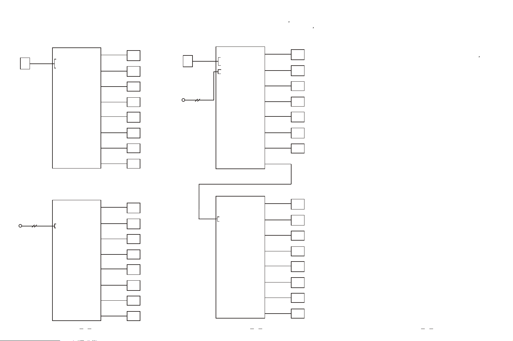
RS-485 star topology bus connection is provided by UT-1208H
RS-485 HUB. Short circuit and opencircuit is providedfor all
the terminals. Photo electrical isolationof 2,500V isprovided.
Re-constru ction of RS-485 bus structure and network range
splitting can beeasily realized toimprove communication reliability.
In the caseof lighting strike or equipment failure the affected
range shall beisolated to make sure the normalfunction of other
ranges. This feature can increasegreatly the reliabilityof existing
RS-485 with achievementof shorter timefor network maintenance.
Proper application ofUT-1208H RS-485 HUB can help you with
a nice designof RS-48 system of high stability.
UT-1208H 8-PORT RS-485 HUB
USER MANUAL
I. Summary
IV. Electric interfaces and definitions:
RS-232C/RS-485 definition
TXD
RXD
SGND
5
485+
485-
23
14
485+ 485-
SGND
23
1
Interpretation of frontpanel indicators:
PWR--Power, greenfor power on.
TXD--Data sending indication,green for normal
transmission from INPUTport to OUTPUTports 1-8.
RXD--Data receiving indication,yellow for normal
transmission from OUTPUTports 1-8 toINPUT port.
E1-E8--Failure alarm indicatorsfor ports 1-8, the lights
stay ON toindicate short circuit or wrong signal
connection of ports1-8. E1 is for port 1,E2 for port
2, and soon. Problems can be determined bythe user
according to different light indicators.
Fig 3. RS-232C/RS-485 input interface Fig 4. RS-485 output interface
1.RS-232C/RS-485 input interface definition
2.RS-485 output interface definition
5-PIN Terminal Interface
1
2
3
RS-485
485+
485-
GND
5-PIN Terminal Interface
1
2
3
4
5
Signal Direction
OUT
IN
Definition
TXD
RXD
SGND
485+
485-
MODEL:UT-1208H
8-PORT RS-485 ISOLATED HUB
PWR1
TXD
RXD
E7
E5
E3
E2
E8
E6
E4
E1
DC9-48V
T/R8+
T/R8
GND
T/R7+
T/R7
GND
T/R6+
T/R6
GND
T/R5+
T/R5
GND
T/R4+
T/R4
GND
T/R3+
T/R3
GND
T/R2+
T/R2
GND
T/R1+
T/R1
GND
RS-485 PORT RS-232/485
TXD
RXD
SGND
485+
485
PWR2
RS-232
( UT-1208H )
1
2
3
4
5
( UT-1208H )
1
2
3
4
5
1
2
3
4
5
Main control
machine
RS-485 deviceA
RS-485 device B
RS-485 device C
RS-485 device D
RS-485 device E
RS-485 device F
RS-485 device G
RS-485 device H
Port 1
Port 2
Port 3
Port 4
Port 5
Port 6
Port 7
Port 8
RS-485 deviceA
RS-485 device B
RS-485 device C
RS-485 device D
RS-485 device E
RS-485 device F
RS-485 device G
RS-485 device H
Port 1
Port 2
Port 3
Port 4
Port 5
Port 6
Port 7
Port 8
IP RS-232Port
IP RS-232Port
OR
RS-485 Bus
IP RS-232PortIP RS-232Port
V. Applicatios of UT-1208H 8-Port RS-485 HUB
1. Applicationin connection from RS-232C serial portof
main control machineto 8 RS-485 interfaces.
RS-485 deviceA
RS-485 device B
RS-485 device C
RS-485 device D
RS-485 device E
RS-485 device F
RS-485 device G
RS-485 device H
RS-232
Main control
machine
IP RS-232PortIP RS-232Port
( UT-1208H )
1
2
3
4
5
Port 1
Port 2
Port 3
Port 4
Port 5
Port 6
Port 7
Port 8
( UT-1208H )
1
2
3
4
5
1
2
3
4
5
RS-485 deviceA
RS-485 device B
RS-485 device C
RS-485 device D
RS-485 device E
RS-485 device F
RS-485 device G
RS-485 device H
Port 1
Port 2
Port 3
Port 4
Port 5
Port 6
Port 7
Port 8
RS-485 Bus IP RS-232PortIP RS-232Port
2. Applicationin expansion from existing RS-485 BUSto 8
RS-485 interface.A maximum of 128 RS-485hubs can be
connected simutaneously toRS-485 BUS.
3. Applicationsin connection from RS-232C serial portof main
control machine tomultiple RS-485 interfaces or in expansion
from existing RS-485BUS to multiple RS-485 interfaces and a
maximum of 128RS-485 hubs can be connected simutaneouslyto
RS-485 BUS.
Efficient solutions of RS-485 ports failures hall greatlyincrease
the liability of RS-485device connections. Theshort circuit protection
fuction of all the4 ports for subordinatemachine shall work under
turn-off mode.Any failure of anyspecific RS-485 port shallonly
influence the RS-485 BUSsystem connected to thatport all
systems connected to otherports will not beeffected. Failed ports
and other devices connectedcan be determined easilyfor solution
by users based onthe alarm indicators.
VI. Alarm and Protection of RS-485 Port Failures
Outside power suplyof DC9-48V/AC100-240V~60/50Hz is
adopted. Never userany other un-regulated power supply to
avoid damage causedto your products.
1,500W lighting strike protectionis available forall the RS-485
interfaces of UT-1208H for efficient restriction of lighting strike
and ESD. Groundinghas to be ensured for asafe and stable
communicationss.
VII. Prtection of Power and Lighting Strike
456