Upsen Queen Star Series User manual

User Manual
High Frequency Online UPS Queen Star Series
3 Phase 10K-40KVA

THANKS
Thank you for purchasing our UPS, it is safe and reliable, needs few
maintenance.
This manual includes instructions of safety installation and operations,
they help your UPS to have the longest service life. This manual also accounts
the UPS work principle and relative functions.
Please obey the instructions and notes stated in this manual. Keep this
manual in a safe place, consult it before operation.
Note: The company reserves the right to make changes to product described
in this manual at any time and without notice for reason of improvement.

Contents
1. Safety.....................................................................................................1-2
1.1 Safety notes......................................................................................................1
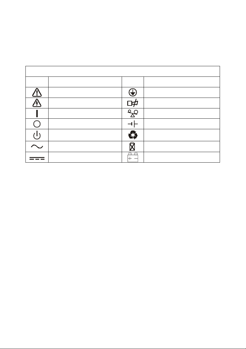
1.2 Description of commonly used symbols..........................................................2
2. Introduction..........................................................................................3-5
2.1 System and model description.........................................................................3
2.2 Functions.....................................................................................................3-4
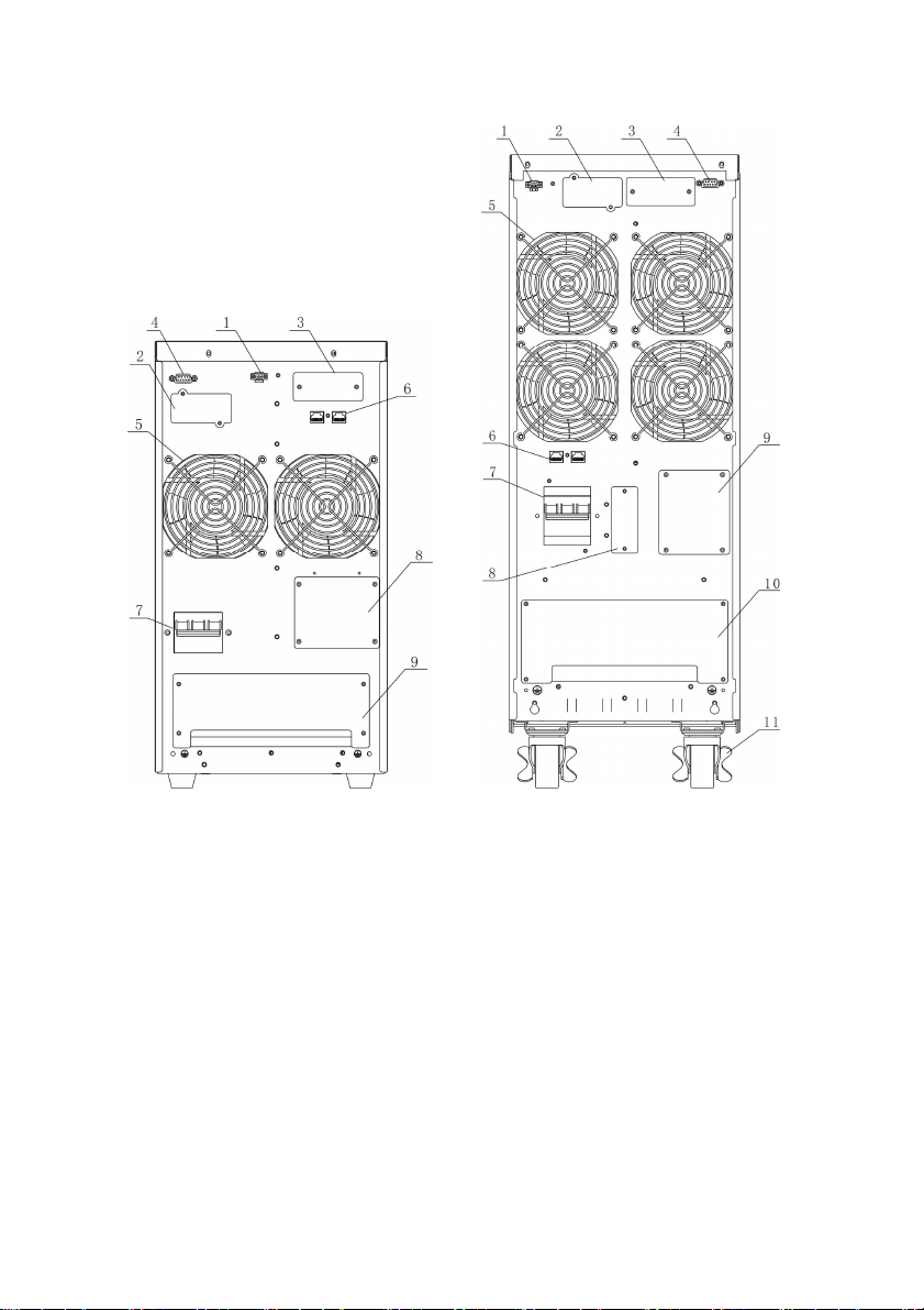
2.3 Appearance......................................................................................................5
3. Installation............................................................................................6-9
3.1 Unpacking and inspection................................................................................6
3.2 Installation notes...........................................................................................6-7
3.3 Installation....................................................................................................7-9
3.4 Operating procedure for connecting the long backup time model UPS with
the external battery..........................................................................................9
4. Parallel operation.............................................................................10-13
4.1 Brief introduction of the redundancy.............................................................10
4.2 Parallel installation........................................................................................10
4.3 Operation and maintenance......................................................................11-13
5. Operation introduce.........................................................................14-19
5.1 Operation Display Panel................................................................................14
5.2 Operation Mode........................................................................................15-19
5.3 Setting the output voltage and frequency......................................................19
6. Communication................................................................................20-21
6.1 RS232 communication..................................................................................20
6.2 AS400 card communication.....................................................................20-21
7. Battery...............................................................................................22-23
7.1 Battery maintenance......................................................................................22
7.2 Notes for battery disposal and replacement.............................................22-23
8. Appendix...........................................................................................24-27
8.1 Fault code.................................................................................................24-25
8.2 Warring code.................................................................................................26
8.3 Specifications and performance.....................................................................27

1
1. Safety
There presents high temperature and voltage in UPS, please obey local safety
rule while installing, operating or maintaining UPS. Abnormal operations may
result in electric shock or equipment damage.
1.1 Safety notes:
1. Even if not connected to main power, high voltage may still presents at UPS
outlets.
2. Don’t dispose of battery or batteries group in fire, otherwise, it can cause
explosion and harm to people. Don’t open or do damage to the battery, for
the liquid spilled from battery is strongly poisonous and do harm to body.
3. Please avoid short-circuit between battery anode and cathode, otherwise, this
will cause electric shock or fire.
4. Don’t dismantle the UPS cover, there is danger of electric shock.
5. Don’t touch batteries. Batteries are not isolated with the input circuit, there
is high voltage between the battery terminals and ground.
Warning:
This product belongs to the C3 type of UPS, used in the second class
environment in commercial and industrial applications. May need to install
restrictions or additional measures to restrain disturb.

2
1.2 Description of commonly used symbols
The following symbols will be used in this manual and may appear during the
course of your practical applications. Therefore, all users should be familiar
with them and understand their meanings.
Notation and Explanation
Notation
Explanation Notation
Explanation
Alert you to pay special attention
Protective ground
Caution of high voltage
Alarm silence
Turn on the UPS
Overload indication
Turn off the UPS
Battery check
Idle or shut down the UPS
Recyclable
Alternating current source (AC)
Do not dispose with ordinary trash
Direct current source (DC)
Battery

3
2. Introduction
2.1 System and model description
The On-Line-Series is an uninterruptible power supply incorporating
double-converter technology. It provides perfect protection specifically for
strict load. The double-converter principle eliminates all mains power
disturbances. A rectifier converts the alternating current from the socket outlet
to direct current. This direct current charges the batteries and powers the
inverter. In the event of power failure, the maintenance-free batteries power the
inverter. Thus the inverter generates a sine wave AC power, which permanently
supplies the loads.
Designed with the proven on-line, double conversion architecture, this series of
UPS offers the greatest degree of availability in power protection and provides
continuous high-quality AC power to connect strict load, especially for the
basic equipments in some areas as: finance, communication, government,
traffic, manufacture, education and so on.
This manual is applicable to the following models:
Type Model Input Battery
Standard
10KVA 33 10K Three-phase + N + PE
Inbuilt
20KVA 33 20K Three-phase + N + PE
Inbuilt
Long
back up
time
10KVAL 33 10KL
Three-phase + N + PE
External battery bank
20KVAL 33 20KL
Three-phase + N + PE
External battery bank
30KVAL 33 30KL
Three-phase + N + PE
External battery bank
40KVAL 33 40KL
Three-phase + N + PE
External battery bank
2.2 Functions
★ Three-in-three-out UPS
33Q 10KL-40KL UPS is big power three-in-three-out UPS, whose load can
be completely imbalance between three phases. When the output connects
imbalance loads, the input currents of three phases are mutually balanced,
so the burden of three phases electric net are balanced.
★ Digital control
Each part of this UPS is implemented under digital control. The advantage
is avoid the risk of analog component invalidation, make the performance
and the control system more excellent, steady and credible.

4
★ N+X parallel redundancy
33Q 10KL-40KL UPS adopts N+X parallel redundancy design, user can
set different redundancy degree according to the important degree of the
load. While the redundancy module attain above two, the dependability of
UPS system achieve 99.999%, satisfying the reliability require of aviation
and finance industry, etc.
★ PFC soft switch
33Q 10KL-40KL Using the cutting edge of PFC soft switch technology,
improve the system of the power grid environment adaptability, system
stability is higher, and to reduce the failure rate of the system and the
machine efficiency is higher than 93%, more energy conservation and
environmental protection.
★ Intelligent monitor function
A local monitor software CD is configured for 33Q 10KL-40KL UPS, UPS
is monitored through RS232 wire conveniently. Remote monitor is feasible
when SNMP card or RS485 convert card is chosen.
★ Maintain bypass
This UPS provide maintain bypass function. Technician can fix the cabinet
interior online by switching to bypass when emergency situation happens.
★ All-purpose UPS
33Q 10KL-40KL UPS support frequency conversion, it can be used as a
transducer.

5
2.3 Appearance
33Q 10KL BACK VIEW 33Q 10K/33 20K(L)/33 30KL/33
40KL BACK VIEW
1. EPO Emergency shutdown switch 1. EPO Emergency shutdown switch
2. SNMP card 2. SNMP card
3. Parallel board install position 3. Parallel board install position
4. RS232 communication interface 4. RS232 communication interface
5. FAN 5. FAN
6. RJ45 6. RJ45
7. Input breaker 7. Input breaker
8. Wiring installation 8. Battery connect position
9. Terminal block 9. Wiring installation
10. Terminal block
11. Wheel
3. Installation

6
3.1 Unpacking and inspection
1. Check if the equipment is just what you wanted to purchase, you can affirm
through inspecting the model NO on back panel of the equipment.
2. Unpack the packaging and check the package contents. The shipping
package contains:
★ A UPS
★ A user manual and a CD
★ A communication cable
★ Long back up time UPS have one battery cable.
3. Inspect the appearance of the UPS to see if there is any damage during
transportation. Do not turn on the unit and notify the carrier and dealer
immediately if there is any damage or lacking of some parts.
4. To unpacking the top of the plate structures in the whole machine packaging
wood base, the machine can be launched along the slope, the diagram below:
3.2 Installation notes
1. Consider the convenience of operation and maintain, the space in front and
back of the cabinet should be 100cm and 80cm respectively.
2. Keep good air circulation around UPS and far away from water, flammable
gas and corrosive.
3. The environment temperature around UPS should keep in a range of 0℃~
40℃. If the environment temperature exceed 40℃, the rated load capacity

7
should reduced by 12 percent per 5℃. The max temperature can’t be higher
than 50℃.
4. There will be phenomena of condensing if the equipment is dismantled or
installed under low temperature. The equipment can't be installed unless it is
full dry at internal and external of the equipment. Otherwise, there will be
danger of electric shock.
5. Battery group is advised used between 15℃~25℃. Don’t place UPS on
the slope and there should keep good air circulation between in-went on
front panel bottom and fan out-vent on rear panel.
6. Use a standard RS232 communication wire to connect the RS232 port and
the same port in computer, then install the software in the computer to
implement monitor of this UPS.
3.3 Installation
Installation and wiring must be performed in accordance with the local electric
code and the following instructions by professional personnel. For safety,
please cut off the mains power breaker before installation. The battery breaker
also needs to be cut off if it is a long backup time model.
1. Open the terminal block cover located on the rear panel of the UPS (please
refer to the appearance diagram).
2. The input and output wires connect to the UPS must accord with follow
sheet:
Model 33Q 10K(L) 33Q 20K(L) 33Q 30KL 33Q 40KL
Firing line
14AWG (2.5 mm2)
10AWG ( 4mm2)
8AWG (6mm2)
6AWG (16mm2)
Zero line
10AWG (4 mm2)
8AWG (6 mm2)
6AWG (16mm2)
4AWG (25mm2)
Ground line
10AWG (4 mm2)
8AWG (6 mm2)
6AWG (16mm2)
4AWG (25mm2)
Note:
Do not use the wall receptacle as the input power source for the UPS, as its
rated current is less than the UPS’s maximum input current. Otherwise the
receptacle may be burned and destroyed.
3. Connect the input and output wires to the corresponding input and output
terminals according to the following diagram.

8
Input and Output Terminal Block wiring diagram of 33Q 10KL
Input and Output Terminal Block wiring diagram of 33Q 10K/33 20K(L)/
33Q 30KL/33 40KL
Note:
You must make sure that the input and output wires and the input and output
terminals are connected tightly.
4. After having completed the installation, make sure the wiring is correct.
5. Please install the leak current protective breaker at the output power
distribution panel of the UPS if necessary.
6. To connect the load with the UPS, please turn off all the loads first, then
perform the connection and finally turn on the loads one by one.
7. No matter the UPS is connected to the utility power or not, the output of the
UPS may have electricity. The parts inside the unit may still have hazardous
voltage after turning off the UPS. To make the UPS have no output, power
off the UPS, and then disconnect the utility power supply.
8. Suggest charging the batteries for 8 hours before use. After connection, turn
the input breaker in the “ON” position, the UPS will charge the batteries
automatically. You can also use the UPS immediately without charging the
batteries first, but the backup time may be less than the standard value.

9
9. If it is necessary to connect the inductance load such as a monitor or a laser
printer to the UPS, the start-up power should be used for calculating the
capacity of the UPS, as its start-up power consumption is too big when it is
started.
3.4 Operating procedure for connecting the long backup
time model UPS with the external battery
1. The nominal DC voltage of external battery pack is 192VDC for 33Q 10K,
and 240VDC for 33Q 20K, 384VDC for 33Q 30K/40K. Each battery pack
consists of 16 /20/32 pieces of 12V “maintenance-free” batteries in series.
To achieve longer backup time, it is possible to connect multi-battery packs,
but the principle of “same voltage, same type” should be strictly followed.
2. For 33Q 10-40K UPS, the procedure of installing battery bank should be
complied with strictly. Otherwise you may encounter the hazardous of
electric shock.
★ A DC breaker must be connected between the battery pack and the UPS.
The capacity of breaker must be not less than the data specified in the general
specification as follow.
Model 33Q 10KL 33Q 20KL
33Q 30KL
33Q 40KL
Battery voltage
192
VDC
240
VDC
384
VDC
384
VDC
Battery current 55.5A 89A 83A 111A
★ Set the battery pack breaker in “OFF” position and connect the 16、20 or 32
pieces of batteries in series. And the battery wires must be follow the sheet
need:
Model 33Q 10K(L)
33Q 20K(L)
33Q 30KL
33Q 40KL
Battery wire
8AWG
(6 mm2)
6AWG
( 16mm2)
6AWG
(16mm2)
4AWG
(25mm2)
3. To complete the connection by plugging the connector of the external
battery cable into the external battery socket of the UPS. Do not attempt to
connect any loads to the UPS now. You should connect the input power wire
to the right position first. And then set the breaker of the battery pack in the
“ON” position. After that set the input breaker in the “ON” position. The
UPS begins to charge the battery packs at the time.

10
4. Parallel operation
4.1 Brief introduction of the redundancy
N+X is currently the most reliable power supply structure. N represents the
minimum UPS number that the total load needs; X represents the redundant
UPS number, i.e. the fault UPS number that the system can handle
simultaneously. The bigger the X is, the higher reliability of the power system
is. For occasions where reliability is highly required, N+X is the optimal mode.
As long as the UPS is equipped with parallel cables, up to 8 of them can be
connected in parallel to realize output power sharing and power redundancy.
4.2 Parallel installation
1. Users need to opt a standard 25-pin communication cable, which should
have 25 cores, corresponding stitches and shield, as the UPS parallel cable.
The length of the parallel cable is appropriate to be less than 3 m.
2. Strictly follow the stand-alone wiring requirement to perform the input
wiring of each UPS.
3. Connect the output wires of each UPS to an output breaker panel first, and
then connect the wiring to the load via the breaker panel.
4. The parallel UPS must be equipped with battery individually.
5. Please refer the figure followed to see the wiring of parallel operation. The
capacity of the breaker must be not less than the specification as follow.
Model No.
Capacity of breaker
33
Q
10K
L
≥32A/250VAC
33
Q
20K
L
≥50A/250VAC
33
Q
30K
L
≥60A/250VAC
33
Q
40K
L
≥80A/250VAC
*The requirement of the output wiring is as follows:
★ When the distance between the UPSs in parallel and the breaker panel is
less than 20 meters, the difference between the wires of input & output of the
UPSs is required to be less than 20%;
★ When the distance between the UPSs in parallel and the breaker panel is
greater than 20 meters, the difference between the wires of input & output of
the UPSs is required to be less than 10%.

11
4.3 Operation and maintenance
1. To perform the general operation, follow the stand-alone operating
requirement.
2. Start up: The units transfer to INV mode simultaneously as they start up
sequentially in utility power mode.
3. Shutdown: the units shut down sequentially in INV mode. When the last one
completes the shutdown action, each unit will shut down the inverter
simultaneously and transfer to bypass mode.
4. To perform the maintenance, follow the stand-alone requirement.

12
33Q 10KL Parallel Installation Wiring Diagram

13
33Q 10K/33 20K(L)/ 33 30KL/33 40KL Parallel Installation Wiring Diagram

14
5. Operation introduce
5.1 Operation Display Panel
1. ON button:
Pressing the ON button more than 1 second (buzzer beeps once), the UPS
system is turned on.
2. OFF button:
By pressing this button more than 1 second (buzzer beeps once) turns off the
UPS system whenever the UPS run under the normal mode/battery mode.
3. Function button
The Function button provides the following functions:
★ Battery self- diagnosis: When the UPS ran in normal mode, pressing this
button more than 5 seconds (buzzer beeps twice) can start the battery
self-diagnosis.
★ Silence function in battery/bypass mode
In battery/bypass mode, when the buzzer beeps, pressing and holding the
function button for more than 5 seconds (buzzer beeps two times) can silence
the buzzer. Press the button for more than 5 seconds (buzzer beeps twice) again
to resume the alarm function.
★ LCD display screen switch
Pressing the function button for more than 1 seconds (buzzer beeps once) to
switch LCD display screen.
4. LED indicators
The LED indicators contains Fault indicator, Bypass indicator, utility power
indicator, Inverter indicator, Battery indicator. The definition of each indicator
is the same as LED panel (refer to table Appendix 1).

15
5.2 Operation Mode
1. UPS operation mode contains normal mode, battery mode and bypass mode,
self test mode and fault mode.
2. Under the four modes, the page showing output voltage and output
frequency is the main display page. Under the fault mode, the page showing
fault code is the main display page.
3. If users need more information about UPS, Pressing the function button can
initiate display screen switch. If the current page is not the main page, UPS
will auto switch back the main page after 30 seconds.
4. In order to extend the LCD usage life, the backlight will turn off after 1
minute without any switch operation. At this point, Users just need to touch
any button briefly, the backlight will be turn on.
5.2.1 Normal mode
When operating in the normal mode, the display of main page on the front
panel is shown as the figure 5-2. The utility power indicator and the Inverter
indicator are turn on. Load information area shows load value, and the battery
level area indicates dynamically when the battery is not full charged (the
battery level icons lit one after another circularly). When the battery is full
charged, all the level icons are turn on.
1. If the utility power indicator blinks, it indicates that there are problems with
reversed polarity (L, N) of site wiring or disconnect with ground. UPS is still
working in normal mode. If the battery indicator is turn on at the same time,
it shows that the voltage or frequency of the utility power is out of the
normal input range of the UPS. The UPS works in battery mode.
Figure 5-2 Normal Mode
2. If load is more than 105 percent, the buzzer beeps twice every second,
meanwhile, the warning icon blinks every second too, reminding that you

16
have been overloaded. You should get rid of some unnecessary loads one by
one to decrease the loads until the alarm clear.
3. If the battery indicator blinks, it indicates that no battery is connected to the
UPS or battery voltage is too low. You should check if battery is properly
connected to the UPS, and press function button more than 5 seconds to start
the battery self-diagnosis. If the connection between battery and UPS is
confirmed without any problem, it may be due to the defect or aging of the
battery, please refer to the “troubleshooting” in chapter 8 to solve the
problem accordingly.
4. The other four display pages are load percent page, actual load page, input
information page and the maximum temperature page.
Note:
Connection to the power generator should be made according to the following
steps:
★ Activate the power generator and wait until the operation is stable before
connecting the output of the power generator to the UPS (be sure that the
UPS is in idle mode). Then, turn on the UPS according to the startup
procedure. After the UPS is turned on, the loads are connected one by one.
★ It recommended that the capacity of the AC generator chosen should double
that of the UPS.
5.2.2 Battery Mode
When operating in the normal mode, the display of main page on the front
panel is shown as the figure 5-3. The battery indicator and the Inverter
indicator are turn on. If the utility power indicator blinks at the same time, it
shows that the utility power is abnormal. Load information area shows load
value, and bat level area shows current battery capacity.
1. When the UPS is running in battery mode, the alarm will beep every 4
seconds. If the “Function” key is pressed for more than 5 seconds, the alarm
will not beep (silence function). Press the “Function” key more than 5 seconds
again to resume the alarm function.

17
Figure 5-3 Battery Mode
2. When the battery capacity decreases, the number of load/battery capacity
indicators turned on will decrease. If the battery voltage drops to the
pre-alarm level (capable of maintaining the backup time for more than 2
minutes), the alarm will beep every second to remind the user of insufficient
battery capacity.
3. The other four display pages are load percent page, actual load page, battery
information page and the maximum temperature page.
5.2.3 Bypass Mode
When operating in bypass mode set up through UPSilon software, the display
on the front panel is shown as the figure 5-4, the utility power indicator and the
bypass indicator are turn on. The load/battery capacity indicator will be turned
on in accordance with the load capacity connected. Load information area
shows load value, and the battery level area indicates dynamically when the
battery is not full charged (the battery level icons lit one after another
circularly). When the battery is full charged, all the level icons are turn on.
1. When operating in bypass mode, the UPS beeps every 2 minutes. If the
“Function” key is pressed for more than 5 seconds, the alarm will not beep
(silence function). Press the “Function” key more than 5 seconds again to
resume the alarm function.
2. If the utility power indicator blinks, it shows that the voltage or frequency of
the utility power is out of the input range of the UPS or there are problems
with reversed polarity (L/N) of site wiring or disconnect to the ground for
protection.
3. The other four display pages are load percent page, actual load page, input
information page and the maximum temperature page.
Other manuals for Queen Star Series
1
This manual suits for next models
6
Table of contents
Other Upsen UPS manuals
Popular UPS manuals by other brands

Tripp Lite
Tripp Lite SmartOnline 220/230/240V Input/Output owner's manual

Xtreme
Xtreme P91-1000 User & installation manual

Delta
Delta Amplon RX series user manual

Delta
Delta VX Series Installation & Operation Quick Guide

Tripp Lite
Tripp Lite SmartPro VS SMART3000VS Specification sheet

Delta
Delta Ultron HPH series user manual