manuals.online logo
Brands
  1. Home
  2. •
  3. Brands
  4. •
  5. Upsite
  6. •
  7. Switch
  8. •
  9. Upsite SF001-PR5 User manual

Upsite SF001-PR5 User manual

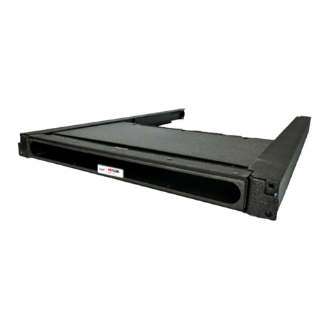
HotLok®Switchx
Part Numbers
SF001-PR5
Installation Guide
Each carton contains:
Switchx adjustable chassis (1), Channel Arms (2), Installation Guide (1)
Tools and Preparation Required for Installation
Tools Required:
Phillips Screwdriver
Hardware Required:
10x32 Cage Nuts (4-8), 10x32 Screws (4-8)
Specications
Part Number Description Dimensions
Quantity per
Carton
Shipping
Weight
SF001-PR5 Passive, Switch Rear Intake,
1U, Adjustable, Black 12.75”-21” (324mm - 533mm) 1 21 lbs.
REAR/HOT AISLE
FRONT/COLD AISLE
Installation Precaution
• Ensure the SwitchFix is installed
so that it does not limit the airow
required for the safe operation of
the equipment.
• Do not interfere with the switch
power cords when installing on a
live unit.
• Take necessary precautions when
handling electrical components.
Installation Guide
The SwitchFix channels mount to the rack rails with mounting screws and cage nuts (not included).
1
Installing the SwitchFix
The front face of the channels are attached to the rack rails using the top mounting holes and the bottom
mounting holes will be used later in the installation process.
2
The rear of the channel is attached to the rack rails using the middle mounting hole for new switch
installations only. If a switch is already installed, the rear face of the channels sit ush against the backside of
the equipment mounting rails and will be supported by the switch housing. Install the channels to the rack
by sliding them over the sides of the switch housing. The channels will attach to the rear rails using cage nuts
and screws (not supplied).
3
Attach channels to rails using 10x32
screws in middle and top RU slots.
SwitchFix inserted into channels
The SwitchFix does not ship in the fully extended position from the factory. Extend the SwitchFix by pulling
evenly on the mounting rail tabs to the deepest depth.
4
Prior to installing the SwitchFix attach the switch power cords to the power supply handle located towards
the center of the switch. The switch power cords can be passed through the SwitchFix brush strip allowing
for a proper seal between the SwitchFix and switch.
5
Once the switch cables are in place push the SwitchFix until it’s tight up against the switch.
6
Make sure the cables are routed correctly and there is no gap between the switch and the SwitchFix.
7
Attach the SwitchFix to the front rack rails using two cage nuts and screws (not supplied).
8
Installation is complete.
9
Pull mounting anges to extend. Slide the SwitchFix into the channels and
mount to the equipment mounting rails using
10x32 screws (not provided).
Rear/Hot Aisle Rear/Hot Aisle
Front/Cold Aisle Front/Cold Aisle
Rear/Hot Aisle Rear/Hot Aisle
Front/Cold Aisle Front/Cold Aisle
Installation Guide
General Information
Effectively Cool Network Switches
In order to provide the best containment of hot and cold
air in the data center it is important to channel cool air
through Top-of-Rack (TORS) network switches. The HotLok
SwitchFix channels cooling air to switch inlets, and also
prevents exhaust air from recirculating to the switch inlets,
thus improving switch reliability and airow management.
Data center energy efciency and switch lifetime can also be
improved.
Maintaining Proper Cooling of Equipment
Failure to follow computer manufacturer’s guidelines for
maintaining proper cooling may result in the overheating
of equipment. Before installing the SwitchFix, ensure that
there is adequate airow to the intake side of the computer
equipment or cabinets through devices such as perforated
oor tiles or grates. Delivering proper airow to the
intake side of computer equipment and/or cabinets is the
responsibility of the customer.
Safety Requirements
Installers must be familiar with standard safety and risk
management practices when working on server rack
equipment or in data center environments.
Customer Support
If you have any questions, please contact us direct at
(505) 798-0200, or Toll Free at (888) 982-7800. Email us
at [email protected]
888.982.7800
www.upsite.com
60407A ©2017
Installation Guide
Limited Warranty
Upsite Technologies, Inc. (the Company) warrants to the original purchaser that products delivered hereunder will be free of defects
in materials and workmanship for a period of twelve (12) months from the date of purchase (the “Warranty Period”).
The Company shall, at its option, within the Warranty Period, either repair or replace free of charge, any product or part thereof
found, upon the Company’s inspection, to be defective in materials and workmanship, and will return the repaired or replaced
product to the purchaser at Company’s expense.
For warranty service and shipping instructions, contact the Company at the telephone number shown below. If the product is
under warranty and the defect appears to be covered by this Limited Warranty, the Company will issue to the purchaser a Notice of
Authorization For Warranty Return. Products returned to the Company for warranty service must be accompanied by a statement of
defect, the Notice of Authorization for Warranty Return provided by the Company, and proof of purchase.
This Limited Warranty is conditioned on the following:
1. The Company must be notied within 12 months of purchase and have been given the opportunity of inspection by return of any
alleged defective product free and clear of all liens and encumbrances to the Company or its manufacturer; and
2. The product must not have been abused, misused, or improperly maintained, and/or non-Upsite authorized repair performed
during such period; and
3. Such defect has not been caused by corrosion or exposure to other than ordinary wear and tear; and
4. The installation and use of the product has been in accordance with the manufacturer’s instructions and not been modied or
customized to include but not limited to cut, resized, burned, glued, bent, re-shaped, disassembled, attachments added to,
improperly installed or used in a manner other than intended.
The company makes no other express or implied warranty or representation of any kind whatsoever including any warranty of
merchantability or tness for a particular purpose and all such other warranties are hereby included.
The Company’s maximum liability hereunder is limited to the purchase price of the product. In no event shall the Company be liable
for any consequential, indirect, incidental, or special damages of any nature arising from the sale or use of the product, whether
based in contract, tort, strict liability, or otherwise.
Note: Some jurisdictions do not allow limitations on incidental or consequential damages or how long an implied warranty lasts, so
that the above limitations may not fully apply. This warranty gives specic legal rights and you may also have other rights which may
vary from jurisdiction to jurisdiction.
For complete warranty and repair information Call (888) 982-7800 or visit upsite.com
U.S. and International Patents Pending
For sales and installation contact:
(800) 328-2256 | www.dataclean.com

Other Upsite Switch manuals

Upsite SF001-PR1 User manual

Upsite

Upsite SF001-PR1 User manual

Upsite HOTLOK Switchfix SF001-PR3 User manual

Upsite

Upsite HOTLOK Switchfix SF001-PR3 User manual

Popular Switch manuals by other brands

Accton Technology ES3616 Management guide

Accton Technology

Accton Technology ES3616 Management guide

pozyx Anchor V2.2 user manual

pozyx

pozyx Anchor V2.2 user manual

ZyXEL Communications PLA-470 Specifications

ZyXEL Communications

ZyXEL Communications PLA-470 Specifications

Steren USB-527 instruction manual

Steren

Steren USB-527 instruction manual

Saitek UFO user manual

Saitek

Saitek UFO user manual

FSR MAS-6100 Installation and operating guide

FSR

FSR MAS-6100 Installation and operating guide

QNAP QSW-M408-4C Quick installation guide

QNAP

QNAP QSW-M408-4C Quick installation guide

Belkin F1DN102KVM-UN-3 user manual

Belkin

Belkin F1DN102KVM-UN-3 user manual

Comprehensive CSW-HDBT300M Operation manual

Comprehensive

Comprehensive CSW-HDBT300M Operation manual

Panasonic AV4 manual

Panasonic

Panasonic AV4 manual

Endress+Hauser nivector FTC 968 Installation and operating manual

Endress+Hauser

Endress+Hauser nivector FTC 968 Installation and operating manual

Western Telematic Remote Power Boot Switch user guide

Western Telematic

Western Telematic Remote Power Boot Switch user guide

Gefen Pro DVI FM 2000 user manual

Gefen

Gefen Pro DVI FM 2000 user manual

Grandbeing GB07SW0501 operating instructions

Grandbeing

Grandbeing GB07SW0501 operating instructions

Transmitter Solutions EIS ENTRY-RX user manual

Transmitter Solutions

Transmitter Solutions EIS ENTRY-RX user manual

EUCHNER NM VZ Series operating instructions

EUCHNER

EUCHNER NM VZ Series operating instructions

TESmart HKS1601A10 quick start guide

TESmart

TESmart HKS1601A10 quick start guide

Larson Electronics EPS-FS-B-2PSW instruction manual

Larson Electronics

Larson Electronics EPS-FS-B-2PSW instruction manual

manuals.online logo
manuals.online logoBrands
  • About & Mission
  • Contact us
  • Privacy Policy
  • Terms and Conditions

Copyright 2025 Manuals.Online. All Rights Reserved.