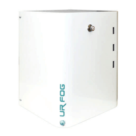
UR FOG BAT 300 Tempest Technology Guide

INSTALLATION AND USE MANUAL
Installation manual vers.1.0 (FW 1.1.1)
ENGLISH MANUAL

1 Introduction page 3
2 Conditions of use and safety requirements page 3
3 Mobile applications page 4
4 Package contents page 4
5 Technical data page 4
5.1 Physical features (Table A) page 4
5.2 Electrical characteristics, consumption and heating time (Table B) page 4
5.3 Performance (Table C) page 5
6 Positioning and installation page 5
7 Cable passages page 7
8 Electronic board page 7
8.1 General view page 7
8.2 Description of the parts (Table D) page 8
9 Usage scenarios for BAT 300 Tempest Technology page 9
9.1 Mode 1: low power, no supply voltage applied page 9
9.2 Mode 2: low power, supply voltage applied, slow charging mode page 9
9.3 Mode 3: low power, supply voltage applied, fast charging mode page 9
9.4 Mode 4: always-on, no supply voltage applied page 9
9.5 Mode 5: always-on, supply voltage applied, slow charging mode page 9
9.6 Mode 6: always-on, supply voltage applied, fast charging mode page 9
9.7 Summary tables page 10
9.8 Low power & Always on modes tables page 10
10 Connection of BAT 300 Tempest Technology page 11
10.1 Principle of activation page 11
10.2 Connection to the alarm panel page 12
10.3 Inputs connection page 13
10.4 Outputs connection page 13
11 Shooting time programming page 14
12 Fluid page 14
13
Batteries page 15
14 External LEDs page 16
15 Final test page 16
16 Application of the window sticker page 17
17 Periodic checks page 17
18 Meaning of the LED’S, Faults & Solutions page 18
19 Accessories and spare parts page 19
20 Certifications page 19
21 Warranty page 19
SUMMARY
2

1INTRODUCTION
Thank you for purchasing a UR Fog product. The great patented technological innovations make UR Fog devices the fog
generators with the best performance in the security market.
The fog generated by UR Fog does not create particular problems or injuries for a human being for a short stay in a fogged
room if the system is used according to the manufacturer’s recommendations.
The fluid and the generated fog are certified as safe for people, animals and foods from an authorized international
certification company and is proved that it does not leave any residual.
UR Fog systems are certified respecting European laws and regulations. Any certifications required in specific countries are
a responsibility of the distributor of that specific country. The documents related to certifications can be requested by mail
UR FOG BAT 300 Tempest Technology operates with very different principles compared to all existing product. It is a
battery operated device able to remain in working condition for many months without mains power while still being able to
shoot for the maximum settable time. With healthy and fully charged batteries it can remain operational without recharging
for more than 6 months. At 6 months it is able to perform a full shot of 60 seconds.
UR FOG BAT 300 Tempest Technology can shoot a maximum of 100 m3 of fog with zero visibility (UR FOG standard).
2CONDITIONS OF USE AND SAFETY REQUIREMENTS
▪This appliance is not intended for use by person (including children) with lack of experience and knowledge, unless they
have been given supervision or instruction concerning use of the appliance by a person responsible for their safety
▪Never use UR Fog products for any purpose that is not related to protection from thief or robbery. The choice of the
conditions of use in case of robbery will be suggested by your security consultant
▪The manufacturer declines all responsibility in case of use of the UR Fog device in the presence of objects and things
that may be damaged in contact with substances containing glycol, water and alcohol
▪Personnel who may be exposed to the fog emitted by the device must be notified in advance and must be checked that
they do not have specific allergies to the aforementioned substances
▪At the date of printing of this manual it has never been pointed out any problem related to any allergy. UR Fog is in no
way responsible for any damage or condition of use that has not been required and specifically approved by any
specific written request prior to the installation of its products
▪With regard to the fluid used, carefully consult the document on the safety of the UR Fog fog fluid published on the
website www.urfog.com
▪Contact a doctor if for any reason you swallow fog fluid or if after contact with eyes or skin you have any kind of
reaction, and in any case wash it immediately with water and soap
▪Do never stay for a long time in a room filled with fog
▪Do not use refills that are not the ones suggested by UR Fog and never try to recharge them, they are made for a single
use. Never use different fog fluids or add any other substance into the refills. Keep UR Fog refills out of reach of people
and animals
▪Follow your national rules for the dispose of empty refills
▪When UR Fog BAT 300 Tempest Technology produces fog avoid staying closer than 1 meter from the device
▪The device must not be exposed to splashing or dripping water. No objects containing liquids must be placed on the
device
▪Do not use or charge the UR Fog device in any kind of vehicle except for the devices intended for this type of use
▪The main body of BAT 300 Tempest Technology should not be opened unless by specific and authorized service centers
▪Do not move the device when it is still hot
3

3MOBILE APPLICATIONS
For any application on moving vehicles, and in general on vehicles circulating on roads and public areas:
▪It is necessary to refer to the regulations in force in the respective Country where the device will be used
▪In the situation that the goods compartment may be in contact with the driver's cab, take all precautions so that the fog
cannot invade the latter
▪It is also necessary to take all precautions so that the device cannot start when the vehicle is in motion, so that the fog
cannot for any reason be generated
4PACKAGE CONTENTS
▪N° 01 security fog generator BAT 300 Tempest Technology
▪N° 02 special batteries 12V / 9Ah
▪N° 01 disposable cartridge of 125 ml fog fluid
▪N° 01 window sticker
▪N° 01 installation manual
▪N° 01 installation template
5TECHNICAL DATA
5.1 Physical features
(Table A)
Dimensions (height x width x depth) mm 300 x 200 x 150
Weight included batteries (Kg) 7,6
Weight without batteries (Kg) 1,9
Colors Pure white RAL 9010 - Matte black RAL 9005
5.2 Electrical characteristics, consumption and heating time
(Table B)
Power supply Battery
Battery model n° 2 custom built lead acid VRLA 12 V - 9 Ah batteries
Autonomy without external power supply About 6 months (at 6 months a full time shoot is guaranteed).
See Chapter 9
Autonomy with external power supply No limit. Batteries replacement recommended every 2 years
Inbuilt battery charger Yes with two external charging current options: 10-16 V / 350 mA and 1 A
External battery charger Connector for external battery charger present
Average power consumption Low power mode: 2-3 mW
Always on mode: 1,2 W
Heating time from cold Immediate at the time of shot
Temperature management Self-balancing of shot with patented system
Opearating temperature range -10°C ..... +50°C
4

5.3 Performance
(Table C)
Performance (m3) visibility 1 meter 100 m3with zero visibility (UR Fog standard) in 60 seconds
(Standard EN 50131-8: 2019)
Number of shots with one cartridge 25 m3(8 shots) – 50 m3(4 shots) – 100 m3(2 shots) + 1 extra test shot
Shot times (sec) 2s (test shot) - 15s (25 m3) - 30s (50 m3) - 60s (100 m3)
6POSITIONING AND INSTALLATION
Please observe the following instructions and read the entire manual carefully for installing BAT 300 Tempest Technology:
Request to UR Fog or its distributors to take part in courses for installers to ensure the optimal installation of the equipment.
▪The device must be installed avoiding to obstruct escape routes. (according to EN50131-8:2019)
▪Verify the fog does not limit the visibility near: stairs, landings, moving objects that may cause falls, injuries or any
damage to persons
▪When using the product in multi-storey buildings, if the escape route runs through an area which is protected by a
fogging system, it is recommended to install a vocal warning that provides instructions on the behavior to observe.
▪Never direct the fog jet towards an object or a wall less than 2 meters away
▪Avoid installing the UR Fog device in front of obstacles that could cause the deflection or blocking of the fog jet, thus
preventing its correct diffusion
▪Be careful to shoot directly against the windows and doors, as in the event of their breakthrough, the fog tends to
escape easily. If these remain open or are uprooted upon intrusion, there is a risk of directing the fog outside the
premises
▪The dead zone is the wall on which the fog generator is installed. This area will be the last to be saturated as the fog
must encounter obstacles to be able to go back. The ceiling dead zone is normally negligible
▪Remember that, depending on the models, the fog jet of the UR Fog devices after the first 3 seconds of delivery can
exceed 10 meters from the point where the device is installed
▪Setting the shooting time interval between the minimum and maximum shown in the shooting table, avoid
“overshooting” even if the produced fog is dry and generally doesn’t leave residue. A shot that goes far beyond the
recommended seconds can create a residue problems in the protected room
▪Install the device at the heights provided for each model by the manufacturer
▪Install the systems so that, when the alarm is not activated, they cannot be tampered, for example by occluding the fog
emission nozzle
▪Don’t activate the UR Fog device before the installation is completed. Insert the bag / cylinder as the last operation
following the procedure described in the manual. It is advisable to perform the first activation test keeping the bag /
cylinder disconnected
▪When the installation is finished, always test the system
▪When carrying out functional tests of the UR Fog device, remember to notify the local Fire Brigade in advance, in order
to prevent false alarms
▪Remember to put warning labels about the presence of UR Fog on the windows or to the access points to the protected
area
▪Report its installation to the firefighters in your area and eventually to other institutions if needed. Use the notification to
the authorities document included in the package
5

Choose the surface
For a correct installation, identify a surface (shelf, wall, ceiling or
other) that guarantees a safe seal. Use screws, anchors and
other restraint systems suitable for the purpose and for the
surface.
Use the installation template as help for a correct positioning the
last page of this manual.
For wall installation use the orientable VESA bracket to direct the
fog downwards (see chapter 20). The fixing holes of the wall
bracket are the same of the BAT 300 Tempest Technology.
200 mm
300 mm
100 mm
100 mm
100 mm
100 mm
Positioning and installation heights
FLUID
Positioning of BAT 300 Tempest Technology fog generators
VERTICAL WALL / SHELF
BAT 300 Tempest Technology maximun installation heights
The distances intended between the point of the fog and the point of impact on floor
MODEL WALL / SHELF WALL / SHELF
BAT 300 Tempest Technology without orientable bracket
Max 1,5 m
with orientable bracket
Max 2,5 m
6

8ELECTRONIC BOARD
8.1 General view
S1 Dual dip-switch to program the shooting time
P1 Jumpers for factory
programming
W7 Jumper reserved
for factory usage
W1 Reserved for factory
usage
W2 Partial service mode
enable
W3 Always-on
/ Low power mode
W4 Active security mode
enable
W5 Defines pin 9 of J11
as PIR or PANIC input
W6 Defines the function
of the PIR input
(TRIG validation
/ stand-alone shooting
command)
FLUID (S2)
Fluid reset button
W8 Jumper to choose
the external charger current
Empty fluid or Fault
System armed
System ready
External signalling LEDs
J11-1 Positive terminal external
10-16 Volt power supply input
J11-2 GND terminal external
10-16 Volt power supply input
J11-3 Empty fluid tank output
J11-4 Fault output
J11-5 Low battery output
J11-6 Internal battery power
output connector
J11-7 ARM input
J11-8 TRIG input
J11-9 PIR/PANIC input
J11-10 GND
J4 Standard 6 pin serial
port connector
J6 Extended 10 pin serial
port connector
J10 Internal 24 V batteries power output connector
to power the Active CLoud board or other devices
J8 Fast charger input connector
Main screwed
connector
7CABLE PASSAGES
Use the provided holes for the passage of the signals, power and LAN Cat. 5 cables
Hole for signal, LAN and battery charging cables
Passage for LAN cable
7

8.2 Description of the parts
(Table D)
J4
J6
J8
J10
J10-1
J10-2
J11
J11 - 1
J11 - 2
J11 - 3
J11 - 4
J11 - 5
J11 - 6
J11 - 7
J11 - 8
J11 - 9
J11 - 10
W1
W2
W3
W4
W5
W6
W7
W8
S1
1 low - 2 low
1 low - 2 high
1 high - 2 low
1 high - 2 high
S2
P1
DL1 RED
DL3 BLU
DL2 GREEN
Standard 6 pin serial port connector
Extended 10 pin serial port connector
Fast charger input connector
DC 24 V 500 mA power output connector to power the Active Cloud board or other devices
+24 V
GND
Main screwed connector (Pin 1 is located in the upper side, close to J4)
Positive terminal external 10-16 Volt
power supply input
GND terminal external 10-16 Volt power
supply input
Empty fluid tank output
Fault output
Low battery output
Internal 24 V batteries power output connector
ARM input
TRIG input
PIR/PANIC input
GND
Reserved for factory usage
Partial service mode enable
Always-on mode / Low power mode
Active security mode enable
(Slightly increases consumption)
Defines pin 9 of J11 as PIR or PANIC input
Defines the function of the PIR input
Jumper reserved for factory usage
Jumper to choose the external power current
Dual dip-switch to program the shooting time 1: left dip-switch 2: right dip-switch
2 sec
15 sec
30 sec
60 sec
Fluid reset button
Block of three jumpers for factory programming
External signalling LEDs (from left to right)
Low-power mode: one blink/min
Always-on mode: LEDs are always on
To connect the Active Cloud board or the other UR Fog
expansion boards (only in Always-on mode)
Besides all the signals on J4 it makes available the power supply
(only in Always-on mode)
Designed for the usage of a fast (1A max) battery charger
+24 V nominal, 500 mA max
Negative terminal
Jumper W8 closed: min current 1500 mA
Jumper W8 open: min current 350 mA
This output (NPN Open Collector max 16 V - 50 mA) closes
towards GND when the fluid canister is empty or in reserve
This output (NPN Open Collector max 16 V - 50 mA) closes
towards GND when there is a malfunction
This output (NPN Open Collector max 16 V - 50 mA) closes
towards GND when batteries are low
24 V nominal, 500 mA max. To be used as an alternative to J10
Normally Open dry contact towards GND
Normally Closed dry contact towards GND (see W5 and W6)
GND
Must be left open
If closed at power-on with S2 pressed: Partial service mode enable
W3 closed: Always-on mode (Recommended only with external supply)
- W3 open: Low power mode
Inversion of the rest state of the ARM - TRIG inputs and of the FLUID
- FAULT - BATTERY outputs from NO to NC
W4 closed: NC - W4 open: NO
W5 closed: PIR input - W5 open: PANIC input
W6 closed: TRIG validation - W6 open: stand-alone shooting command
Don't touch
Defines the maximum input current value.
See pin J11-1 and J11-2
W8 closed: min current 1500 mA - W8 open: min current 350 mA
For testing purpose. The next shot will be allowed after 1 minute
25 m
3
. The next shot will be allowed after 5 minutes
50 m
3
. The next shot will be allowed after 10 minutes
100 m
3
. The next shot will be allowed after 20 minutes
Also used to set the partial service mode together with W2
Don't touch
Empty fluid or Fault
System armed
System ready
Name Function Note
Tempest board TEMPEST line
8

9USAGE SCENARIOS FOR BAT 300 TEMPEST TECHNOLOGY
By properly setting some jumpers on the pcb, the TEMPEST BAT 300 device can be set to work in one of six possible modes
as described below.
ATTENTION: all jumpers must be inserted / removed ONLY with the device turned off for both low-power
and always-on modes.
9.1 Mode 1: Low power mode / No supply voltage applied
Configuration: W3 open, J11 pin 1-2 not connected
In this mode the device operates fully disconnected by the mains supply. With new and fully charged batteries TEMPEST is
able to work for at least 6 months while still being able to make a full time shot with the remaining charge.
The serial interface is disabled so no network connection is possible.
9.2 Mode 2: Low power mode / Supply voltage applied / Slow charging mode
Configuration: W3 open, W8 open, J11 pin 1-2 with supply voltage 10-16V, min 350 mA
In slow charging mode the internal battery charger is enabled and it takes roughly 20 h to completely recover the energy lost
in a full time shot (60 s).
The serial interface is disabled so no network connection is possible.
9.3 Mode 3: Low power mode / Supply voltage applied / Fast charging mode
Configuration: W3 open, W8 closed, J11 pin 1-2 with supply voltage 10-16V, min 1.0 A
In fast charging mode the internal battery charger is enabled and it takes roughly 6 h to completely recover the energy lost in
a full time shot (60 s).
The serial interface is disabled so no network connection is possible.
9.4 Mode 4: Always-on / No supply voltage applied
Configuration: W3 closed, J11 pin 1-2 not connected
In always-on mode the electronic board has all its subsystems always powered on. With new and fully charged batteries
TEMPEST is be able to work for at least 4-5 days, and around 2 days with an Active Cloud board.
The serial port is enabled and fully working so an Active Cloud board can be connected and the device can be accessed from
remote locations. A 24V12V DC/DC converter is necessary to supply the Active Cloud board (or any other piece of
equipment that requires +12 V DC, as is usual in the security field).
9.5 Mode 5: Always-on / Supply voltage applied / Slow charging mode
Configuration: W3 closed, W8 open, J11 pin 1-2 with supply voltage 10-16V, min. 350 mA
In always-on mode the electronic board has all of its subsystems always powered on. In Slow charging mode the internal
battery charger is enabled and it takes up to 3 days to completely recover the energy lost in a full time shot (60 s).
The serial port is enabled and fully working so an Active Cloud board can be connected and the device can be accessed from
remote locations but no current can be drawn from the device so any add-onboard must be powered from an external
source.
9.6 Mode 6: Always-on / Supply voltage applied / Fast charging mode
Configuration: W3 closed, W8 closed, J11 pin 1-2 with supply voltage 10-16V, min. 1.0 A
In always-on mode the electronic board has all of its subsystems always powered on. In Fast charging mode the internal
battery charger is enabled and it takes up to 8 hours to completely recover the energy lost in a full time shot (60 s).
With the Active Cloud board connected the time raises to around 10 hours.
The serial port is enabled and fully working so an Active Cloud board can be connected and the device can be accessed from
remote locations. A 24V->12V DC/DC converter is necessary to supply the cloud board (or any other piece of equipment that
requires +12 V DC, as is usual in the security field).
9

9.7 Summary tables
The following tables constitute a useful reference to correctly identify and choose the best connection method. The estimated
on-time is calculated taken into account a couple of brand new and fully charged original batteries. The impact of a low
power PIR sensor connected and powered by the device is also evaluated (not significant).
Operating mode
BAT 300
Tempest Technology
self-powered with
internal batteries only
(no external supply
voltage applied)
Active Cloud Low power PIR sensor Estimated on-time
Low power mode
Always-on mode
No
No
Yes
No
Yes
No
Yes
No
Yes
6 months
4 months
4 - 5 days
4 - 5 days
2 days
2 days
Table 1 - Estimated on-time in low power mode / always on mode, internal batteries only
Charging mode
BAT 300
Tempest Technology
powered with external
supply voltage
Operating mode Active Cloud Estimated single shot
(60 s) recharge time
Slow charge
Fast charge Always-on mode
No
No
No
No
Yes
20 h
3 days
6 hours
8 hours
10 hours
Low power mode
Always-on mode
Low power mode
Table 2 - Estimated single shot (60 s) recharge time
9.8 Low power mode & Always on mode tables
LOW POWER MODE W3 CLOSED LED's 1 blink/min
1: NO SUPPLY VOLTAGE 2: NO SUPPLY VOLTAGE 3: NO SUPPLY VOLTAGE
SLOW CHARGING MODE FAST CHARGING MODE
J11 PIN 1-2
NO supply voltage
J11 PIN 1-2
WITH supply voltage 10÷16V
350 mA minimum
Max recharging current 60 mA
W3 OPEN W3 CLOSED
J11 PIN 1-2
WITH supply voltage 10÷16V
1,5 A minimum
Max recharging current 200 mA
TEMPEST should be able to work for at least
6 months while still being able to make a
full time shot with the remaining charge
20 hours to completely recover the
energy lost in a full time shot of 60 sec
6 hours to completely recover the
energy lost in a full time shot of 60 sec
Serial interface disabled / no network connection / Active Cloud board CANNOT be connected
Every other device draining current from
onboard batteries will decrease the working
time from 6 months to some days / some
hours. With a low power PIR sensor: 4
months
The external voltage can be delivered
by the alarm panel itself. Minimum
current available from the alarm panel
supply output must be greater than or
equal to 350 mA
The external current CANNOT be
delivered by the alarm panel (minimun
available current must be greater than
or equal to 1 A). An external power
supply is necessary
10

ALWAYS ON MODE W3 CLOSED LED's 1 blink/min
4: NO SUPPLY VOLTAGE 5: SUPPLY VOLTAGE 6: SUPPLY VOLTAGE
SLOW CHARGING MODE FAST CHARGING MODE
J11 PIN 1-2
NO supply voltage
J11 PIN 1-2
WITH supply voltage 10÷16V
350 mA minimum
Max recharging current 60 mA
W3 OPEN W3 CLOSED
J11 PIN 1-2
WITH supply voltage 10÷16V
1,5 A minimum
Max recharging current 200 mA
The electronic board has all its subsystems
always powered on.
Estimated on-time with new and fully
charged batteries: 4-5 days. With Cloud
board connected: 2 days
Up to 3 days to completely recover the
energy lost in a full time shot of 60 sec
Up to 8 hours to completely recover
the energy lost in a full time shot
of 60 sec
With Cloud board connected:
around 10 hours
Serial interface enabled / network connection / Active Cloud board CAN be connected
Every other device draining current from
onboard batteries will decrease the working
time from 4-5 days to some days / hours
The external voltage could be
delivered by the alarm panel itself.
Care must be taken to ensure the
minimum current available from the
alarm panel supply output must be
greater than or equal to 350 mA,
increasing to 500 mA with Cloud
board connected
Because of the higher current
requirements, it could not be possible
to supply the TEMPEST machine from
an alarm panel thus making an
external power supply a necessary
part
A 24V12V DC/DC converter is necessary to
supply the cloud board or any other piece of
equipment that requires +12 V DC
No current can be drawn from the
machine so any add-onboard must be
powered from an external source
A 24V12V DC/DC converter is
necessary to supply the cloud board or
any other piece of equipment that
requires +12 V DC
10 CONNECTION OF BAT 300 TEMPEST TECHNOLOGY
10.1 Principle of activation
To shot fog the following requirements must be fulfilled SIMULTANEOUSLY:
- Fog Generator Ready (green LED steady on) and no critical error present
- Alarm system armed (ARM input active - blue LED steady on)
- Intrusion alarm signal on the TRIG input
- Alarm validation on the PIR input (if present)
11

DAYTIME
Alarm system DISARMED ARM Open
Fog device DISARMED
NIGHTTIME
Alarm system ARMED ARM Closed
Fog device ARMED
NIGHTTIME - ALARM
Alarm system ARMED ARM Closed
Intrusion detected TRIG closed
Intrusion not verificated PIR closed
Fog device READY TO SHOOT
NIGHTTIME + ALARM + VERIFICATION
Alarm system ARMED ARM Closed
Intrusion detected TRIG closed
Intrusion verificated PIR open
Fog device SHOOTING
TRIG (NO)
ARM (NO)
PIR (NC)
GND
TRIG (NO)
ARM (NO)
PIR (NC)
GND
TRIG (NO)
ARM (NO)
PIR (NC)
GND
TRIG (NO)
ARM (NO)
PIR (NC)
GND
10.2 Connection to the alarm panel
BAT 300 Tempest Technology can be connected to an alarm panel in the same way as other models of the UR Fog range.
It can be also driven by the serial interface (i.e., with an Active Cloud Board as example).
1) +12 V power supply input
2) GND power supply input
3) Empty fluid tank ouput
4) Fault ouput
5) Low battery ouput
6) Internal battery power ouput
7) ARM Input
8) TRIG Input
9) PIR/PANIC Imput
10) GND
12

Alarm system panel
NPN open collector ouputs
closed to ground
EMPTY FLUID
FAULT
GROUND
LOW BATTERY
10.3 Inputs connection
The ON/OFF output of this alarm panel is an NPN Open collector open when the system is OFF, which closes permanently to
ground (GND) for as long as the same remains in ON.
This output is connected to the pin 7 “ARM”.
Alarm system panel
NPN open collector ouputs
closed to ground
OC1 NA BISTABLE
OC2 MONOSTABLE
GND
PIR SENSOR
ARM
TRIG
GROUND
PIR/Panic input
Input 9 can be defined as PIR verification or Panic by adding a jumper across W5. W5 closed: PIR input W5 open: PANIC
button. This is an open collector input. (Dry contact to Gnd).
PIR input mode
Whit W5 closed, the jumper W6 defines the function of the PIR input. W6 closed: TRIG validation W6 open: stand alone
shooting command
10.4 Outputs connection
The EMPTY FLUID
(NPN Open collector 50mA max) output closes
to ground (GND) when the fluid cartridge is
empty or in reserve (one shoot still available).
The FAULT
(NPN Open collector 50mA max) output closes
to ground (GND) when is a malfunction.
The LOW BATTERY
(NPN Open collector 50mA max) output closes
to ground (GND) when batteries are low.
The ALARM output of this alarm panel is an NPN Open collector open when the system is
OFF, which closes to ground (GND) for XX seconds in case of intrusion.
This output is connected to the pin 8 “TRIG”.
The PIR sensor is a normally closed to
ground (GND) contact wich open in case of
detection.
It’s connected to the pin 9 “PIR”.
The ground (GND) of the alarm panel is
permanently connected to the pin 10
“GND” of TEMPEST.
13

The device will not accept a shooting command before this time interval expires. Although by power cycling the device could
be forced to shoot immediately, without waiting for the inter-shot interval time expiration. This will probably destroy the
device. THEREFORE DO NOT BYPASS WAITING TIME!
11 SHOOTING TIME PROGRAMMING
There are four possible configurations to program the shooting time via the S1 dipswitch. The dipswitch can be set before
any shot and there is no need to power cycle the device to set the shooting time.
2 seconds 15 seconds 30 seconds 60 seconds
Note: After a shot the processor introduces a cooling time during
which any subsequent shot is not allowed until after a specific
time has elapsed:
2 s shot – 1 minute min delay
15 s shot – 5 minute min delay
30 s shot - 10 minute min delay
60 s shot - 20 minute min delay
12 FLUID
The fluid solution is provided in non-pressurized cartridge making it easy to substitute. A self-aligning
mechanism ensures that the cartridge is always fitted correctly. The contents of the cartridges are
mechanically determined and may vary + or - 5%, and each cartridge contains enough fluid to allow
for 2 full time shots (60 s) and at least one test shot (2 s). Fluid cartridges are disposable and CANNOT
be recharged.
Fluid cartridge capacity (ml)
Disposable non-pressurized cartridge
Certified White Out Food Grade fluid
Performance (m
3
) visibility 1 meter
(Standard EN 50131-8: 2019)
Number of shots with one cartridge
Shot times (sec)
125
Yes
Yes
100 m
3
with zero visibility (UR Fog standard) in 60 seconds*
25m
3
(8 shots) – 50m
3
(4 shots) – 100m
3
(2 shots) + 1 extra test shot
2s (test) - 15s (25m
3
) - 30s (50m
3
) - 60s (100m
3
)
* The cubic meters of generated fog are based on the rules defined by the EN 50131-8: 2019 standard which prescribes a visibility of
less than 1 meter. The cubic meters of generated fog mentioned in the table are based on the UR Fog standard which prescribes a
visibility of 50 cm.
Technical data (Table E)
Insert or change the fluid cartridge
NOTE 1: The device will autonomously detect a low fluid condition and it will stop shooting. In this case no try to shoot again!
NOTE 2: Before removing the cabinet, check that the alarm control unit is in the “Service” condition, so as to be sure not to
cause accidental shot.
NOTE 3: To insert or change the fluid cartridge is not necessary to turn off the fog generator.
WARNING!! All UR FOG fogging systems should only be used with UR FOG-branded fluids.
It is strictly forbidden to use any fluid not previously authorized in writing by UR FOG srl.
14

CARTRIDGE REPLACEMENT WITHOUT FLUID ALARM CONDITION OR WITH ALARM CONDITION BUT CARTRIDGE NOT EMPTY
- Unscrew the empty bottle
- Insert the new cartridge and screw it all the way in without overtightening
- Press the fluid reset button FLUID (S2) 1 second until the buzzer sounds
NOTE4: At each cartridge change, check that the silicone nozzle protection is integral with the
nozzle itself and does not come off easily. In this second case, replace the protection with a new
on one.
13 BATTERIES
BAT 300 Tempest Technology is powered by two,
bespoke, lead acid VRLA 12 V - 9 Ah batteries.
With healthy and fully charged batteries it can remain
operational without recharging for more than 6 months.
At 6 months it is still able to perform a full shot of 60
seconds.
For use in the absence of power supply (stand
alone mode) it is necessary to fully charge the
batteries before the first activation.
NOTE 1: The use of standard batteries available on the
market doesn’t guarantee the performances declared in
this manual
IInsert or change the batteries
To insert and replace the batteries, follow the rules as below:
- Open the compartment cover
- Disconnecting and removing the old batteries (if present)
- Insert the new batteries into the compartment
- Close the compartment cover ensuring that the battery supply cables are out and accessible
- Connect the batteries connectors firmly AS FAR AS THEY WILL GO
- The buzzer plays three notes and the three LEDs blink for 5 seconds (Low power mode) or steady on (Always on mode)
CARTRIDGE REPLACEMENT IN FLUID ALARM CONDITION AND EMPTY CARTRIDGE (cartridge ended during shot, firing test
with cartridge empty or without cartridge)
- Unscrew the empty bottle
- Insert the new cartridge and screw it all the way in without overtightenin
- Press the fluid reset button FLUID (S2) 5 seconds until the buzzer sounds**
- Perform a 2 second shooting test
** At this time a small puff of fog might come out from the nozzle.
Don’t stand in front of the nozzle in this period!
15

NOTE 2: after 2 minutes from the connection the electronic board test the batteries powering the heating system. At this
time a small puff of fog might come out from the nozzle. Don’t stand in front of the nozzle in this period.
NOTE 3: in any case, don’t position yourself below one meter away from the nozzle when the device is switched on.
14 EXTERNAL LEDs
DL1 DL2 DL3
BAT 300 Tempest Technology provide three external LEDs.
The LEDs will emit a short blink once per minute (Low-power mode) or are always active (Always on mode) as follows:
Red LED to indicate the empty fluid or a fault
Blue LED to indicate the arm status
Green LED to indicate the ready condition
See Chapter 19 about errors and their solutions.
15 FINAL TEST
At the end of each installation it is essential to test the entire safety system (alarm panel, fog generator, other devices). Here's
a CHECKLIST example for finalizing the installation:
- Check all signals to and from the alarm system
- Check that the fog device is READY before carrying out the test (System READY = GREEN LED on)
- Make a FULL TEST SHOOTING at the installation site, to ensure that the dimensioning is OK
- After the test insert a new refill and RESET the fluid counter
- Register the device on the free ACTIVE CLOUD platform (if an ACTIVE CLOUD LAN WiFi card is present)
- Make sure to give a full INSTRUCTION to the end-user of this installation
16

17 PERIODIC CHECKS
UR Fog security fog systems do not require special controls. The system monitors its functions 24 hours a day, reporting any
anomalies. It is therefore sufficient to manage the reports correctly.
It’s however recommended to periodically check the entire safety system.
Regarding the fog generator, here is an example of checklist:
- Make sure the batteries are not hot and / or swollen. In any case, always refer to chapter 13 Batteries
- Check that the closing screws and wall fixing screws are well tightened and if necessary tighten them fully
- Check that the nozzle is not deformed and that there are not foreign bodies inside it
- Annually check the pneumatic seal of the circuit and the pump by firing fog. If you don’t want to emit the set amount of
fog, simply use the test shot function (2 seconds)
- Intervention report redaction and release of conformity declaration according to local rules
16 APPLICATION OF THE WINDOW STICKER
The window sticker provided with each UR Fog fog Generator is required to warn
and deter intruders from committing theft in the protected facility.
The signage must be displayed prominently on the building protected by the UR
Fog fog generator according to EN50131-8:2019. It is double-sided to allow
visibility from the outside as well as from the inside.
17

18 MEANING OF THE LED’S, FAULTS & SOLUTIONS
GREEN/BLUE/RED Led's are steady ON together for 5 sec
The GREEN LED is OFF
The GREEN LED is steady ON
The BLUE LED is OFF
The BLUE LED is steady ON
The RED LED is OFF
The RED LED is steady ON
The RED LED blinks
LED STATUS CAUSE BUZZER
ALWAYS-ON MODE: LED's always ON
MEANING
Connection of the batteries - system switched ON
System not ready
System ready
System not armed
System armed
No fault
Fluid cartridge is in reserve or empty, batteries low
Hardware failure or inefficient batteries
3 tones
No tone
Status
Status
Status
Status
Status
Status
Fault
Fault
GREEN/BLUE/RED Led's are steady ON together for 5 sec
The GREEN LED is OFF
The GREEN LED blinks 1 time / min
The BLUE LED is OFF
The BLUE LED blinks 1 time / min
The RED LED is OFF
The RED LED is steady ON
The RED LED blinks 1 time / min
LED STATUS CAUSE BUZZER
LOW POWER MODE: LED's blinks 1 time / minute
MEANING
Connection of the batteries - system switched ON
System not ready
System ready
System not armed
System armed
No fault
Hardware failure or inefficient batteries
Fluid cartridge is in reserve or empty, batteries low
3 tones
No tone
Status
Status
Status
Status
Status
Status
Fault
Fault
Low batteries
Inefficient batteries
Fluid reserve
Empty fluid
The voltage on +12 V input is too low or too high
Impossible to arm the device. BLUE LED doesn’t switch ON
The device is armed, BLUE LED is ON but doesn’t shoot
The silicone nozzle protection is loose and no longer fixed
PROBLEM RESULT / CAUSE BUZZER
Troubleshooting
SOLUTION
Replace or recharge batteries - See chapter 13
Change the fluid cartridge and press the fluid button
3 tones
2 tones
No tone
Shot is still available
Shot is not available
A shot is still
available
Shot is not available
Batteries are not
charging
Wiring error
Jumper W4
configuration error
Wiring error
Jumper W4
configuration error
The front RED LED
is ON
Check the external power supply or the alarm panel
output
Check the wiring, the ARM input should be
connected to the GROUND when the anti-theft
system is activated
Check the right configuration of the ARM input:
W4 open: NO W4 closed: NC
Check the wiring, the TRIG input should be connected
to the GROUND when the anti-theft system is
activated
Check the right configuration of the TRIG input:
W4 open: NO W4 closed: NC
A fault is present. Search in this guide
Change the nozzle protection. See chapter 12 Fluid
TEMPEST line: Meaning of the LED's, Diagnostic and troubleshooting
18

19 ACCESSORIES AND SPARE PARTS
Use the accessories provided by UR Fog to optimize the installation.
20 CERTIFICATIONS
All UR Fog devices and fluids comply with the provisions of the European and international authorities.
Any certifications required in a specific country are the responsibility of that country's distributor.
21 WARRANTY
The warranty of UR Fog BAT 300 TEMPEST TECHNOLOGY is 1 year.
The warranty of the cartridges and of the contained fluid is 2 years.
The warranty of the batteries is 1 year, and only the production faults are covered.
The warranty is handled directly from the dealer or authorized installer, so please contact your supplier to take advantage of
warranty with the copy of the purchase document that contains the serial number of the machine. Not included in the
warranty: moving parts and/or damages depending on the incorrect use unless it is found a manufacturing defect in origin.
BY BREAKING THE SECURITY LABELS AND THE OPENING OF THE MACHINE YOU WILL ACCEPT
WHAT IS WRITTEN ON THIS MANUAL AND ON THE WEB SITE: www.urfog.com
BAT 300 (Fluid refill and 2 battery included)
12V 9Ah battery
Fluid refill
Active Cloud LAN/WIFI board with cables (WIFI opt.)
WIFI antenna module
24V - 12V adapter cable (Active Cloud, etc.)
External fast charger
220V power supply
Silicone nozzle protection
Orientable wall bracket
Product code
FPUB300
FPUBBY
FPUBFT
URCLWFC
URCLWFA
FPUBAC
FPUBEFC
FPUB220PS
FPUBNP
FPUWB
Accessories and spare parts
We recommend to throw away the batteries in the appropriate waste containers for recycling.
19

TO USE UR FOG FOGGING SYSTEMS WITH PURIFOG/PURIFOG
HYPO FLUIDS FOLLOW THE DATASHEETS INSTRUCTIONS
AVAILABLE FOR DOWNLOAD ON WWW.PURIFOG.COM
UR FOG S.r.l. Via Toscana 38 - 10099 San Mauro Torinese - Italy
UR FOG Srl reserves the rights to modify the characteristics of the product
for the sole purpose of improving its characteristics and performance.
Report the successful installation to the authority
using the form that can be downloaded from the
FORM FOR THE AUTHORITIES
This manual suits for next models
1
Table of contents
Other UR FOG Security System manuals