8 08-315 (4/28/16)
Initial Setup
CS540 – On the bottom of the base unit set the Configuration Switch to the letter “A”. Set both the
Listening Volume and Speaking Volume dials to the number “3”.
CS50 / CS55 – Set the Configuration Dial on the left side of the base unit so the number “1” is
facing to the front of the base. Set the switch on the right side of the base unit to the single tic mark.
CS50 / CS55 – Set the Master Speak Volume located on the bottom of the base unit to the “B”
position and the Master Listen Volume located on the back of the base to the number “2” position.
Fine Tuning the Volumes
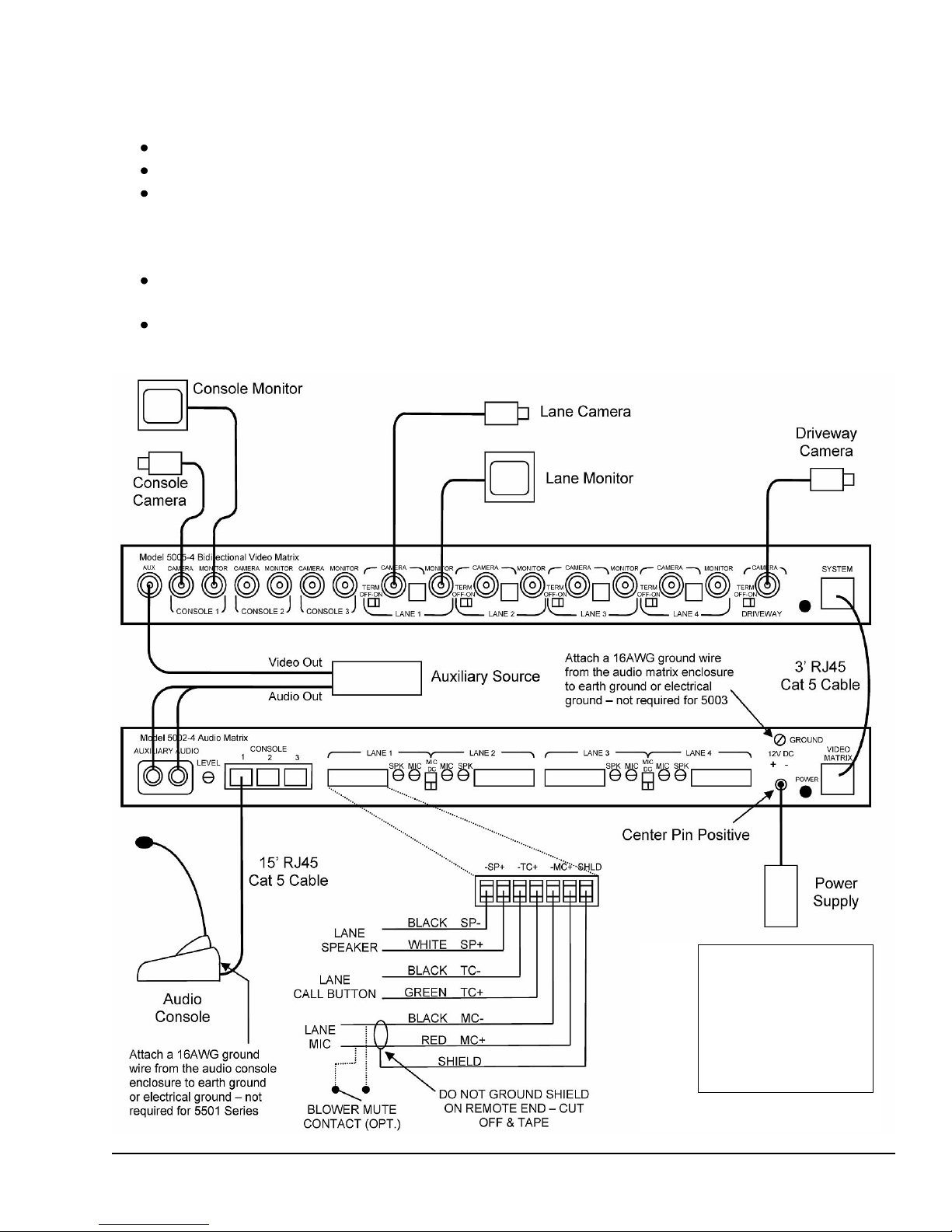
Make sure the speaker and microphone gain pots on the audio matrix have already been set for each
lane while in Console Mode. Never adjust these pots while using the headset. (See the section
“Adjusting the Audio System” later in this document.) You then switch to Wireless Mode and fine
tune the wireless volumes to match the console volumes.
CS540 – The rocker dial on the top end of the headset fine tunes the incoming volume. Be careful
not to press in on this dial accidentally as this dial is also the mute switch. Changes to the volume
dials on the bottom of the base can also be made if necessary.
CS50 / CS55 – The up (+) and down (-) buttons on the back of the wireless base fine tune the
outgoing volume. Each press of a button changes the volume one step. The rocker dial on the top
end of the headset fine tunes the incoming volume. Be careful not to press in on this dial accidentally
as this dial is also the mute switch.
Changing Between Console & Wireless Headset Use
With 5501 series consoles – Press the Wireless button (picture of antenna) while no lane is selected.
The yellow LED next to the button indicates wireless mode when lit.
With newer 5001 series consoles with built-in adapter – Press the Wireless/Camera button while no
lane is selected. The yellow LED under the microphone boom indicates wireless mode when lit.
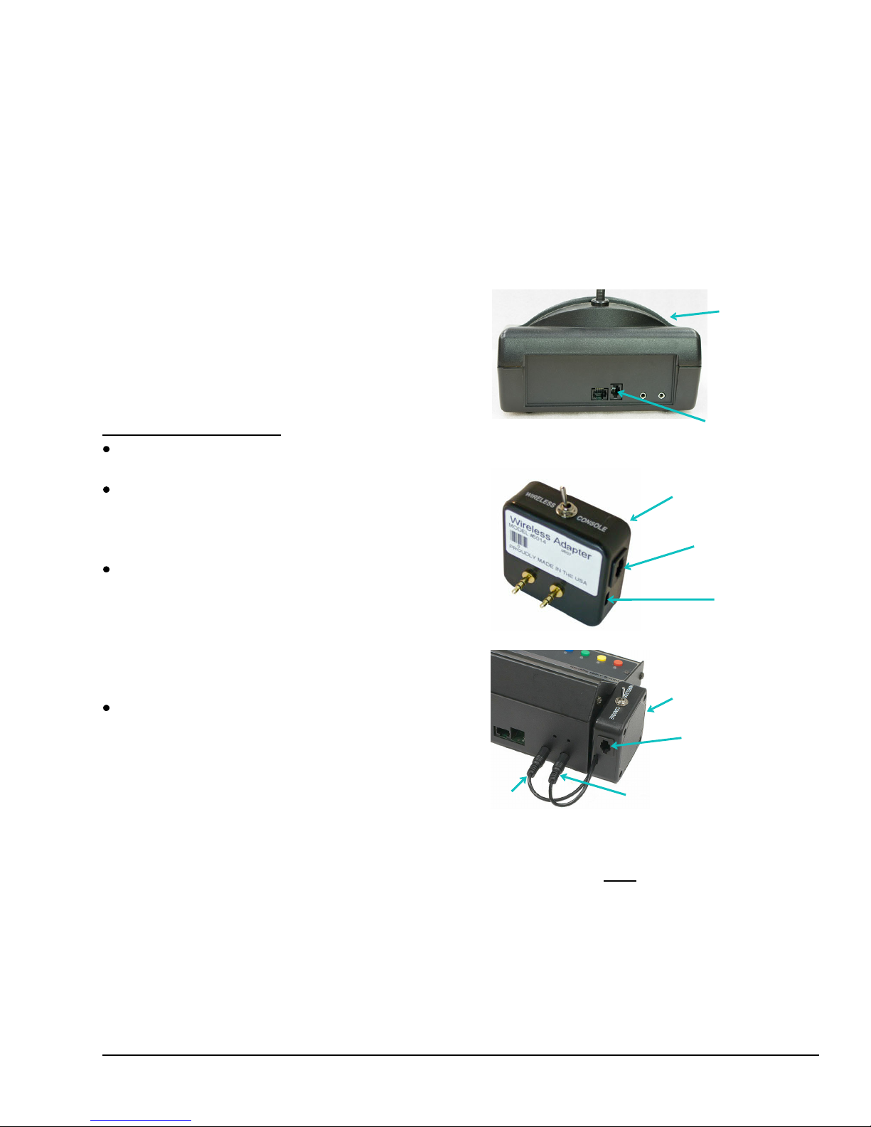
With older consoles which require the 5014 Wireless Adapter – Use the toggle switch on the adapter
to switch between console and wireless mode.
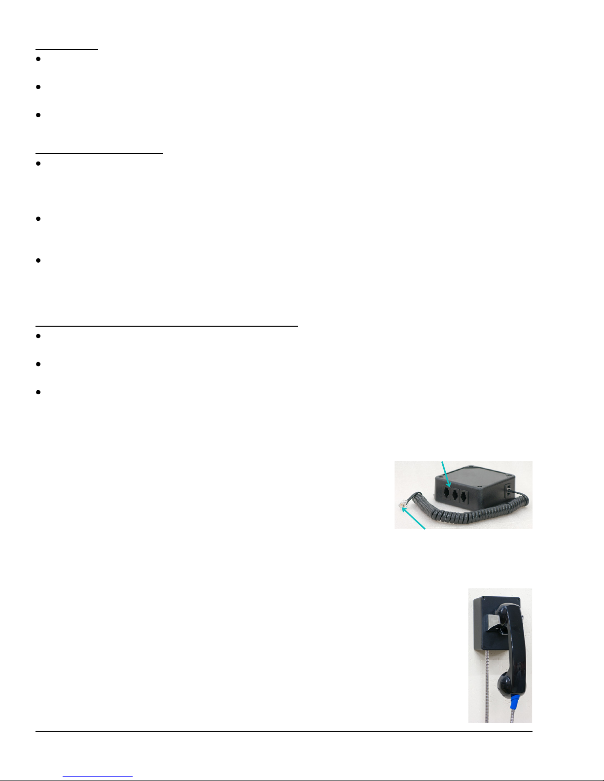
E10052 Wireless Expansion Adapter
The E10052 Wireless Expansion Adapter is used to attach multiple
wireless headset base units to a single audio console. The adapter
includes a short cable to connect it to the audio console. Additional jacks
on the adapter are used to connect up to three headset base units.
When using the expansion adapter, if multiple headsets are active at
the same time the volumes may be slightly reduced.
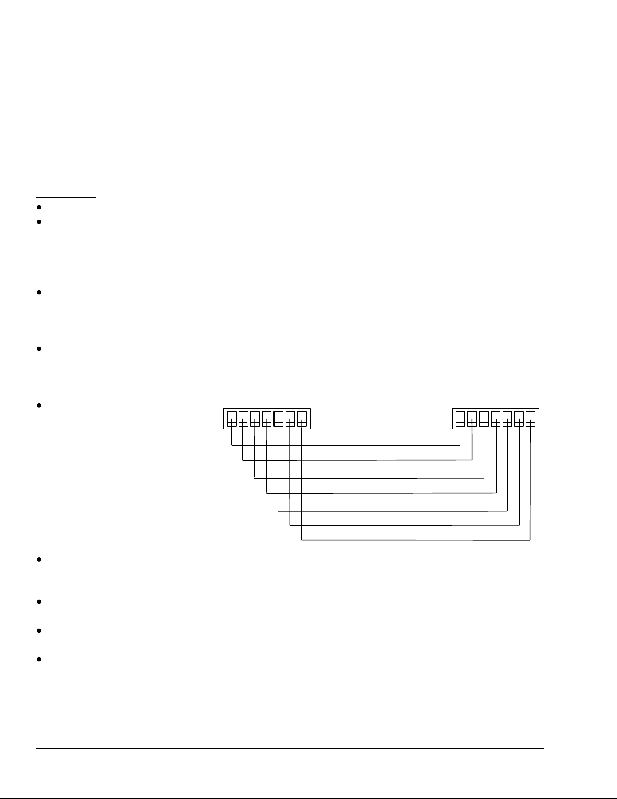
5512 Remote Handset Installation
The Model 5512 Handset is a replacement for the older Model 5012W (wall mount) and
5012H (side mount) handsets. It provides customer privacy and can be used with 4000
and 5000 Series audio systems. The only operational difference is removing the handset
of the 5512 from its cradle does not initiate a Teller Call like the 5012 did; a local call
button must be used for this purpose. However, the remote station speaker and
microphone are disconnected while the 5512 handset is off hook, just like the 5012.
Important Note: The handset used with the 5512 is different from the 5012 handset
and they are not directly interchangeable. Plus the current 5512 handset has a volume
roller which allows a customer to increase the volume if necessary. Also note that local
power was required for the older 5012 but is not needed with the 5512.
Connect up to 3 wireless
headset base units
Connect directly to console or
5014 adapter as appropriate