URC Total Control MRX-4SEN2 User manual

MRX-4SEN2
Owner’s Manual
Total Control MRX-4SEN2
Owner’s Manual

Total Control MRX-4SEN2
Owner’s Manual
Rev 1.0
Technical Suppor t
Toll Free: 800-904-0800
Main: 914-835-4484
techsupport@urc-automation.com
H o u r s : 9 : 0 0 a m - 5 : 0 0 p m E S T M - F
Table of Contents
Introduction ........................................................................................................................................................................................................................................................................1
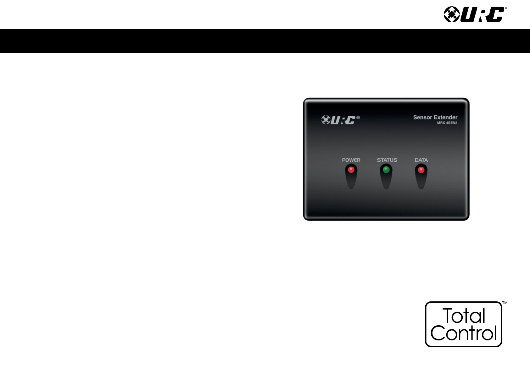
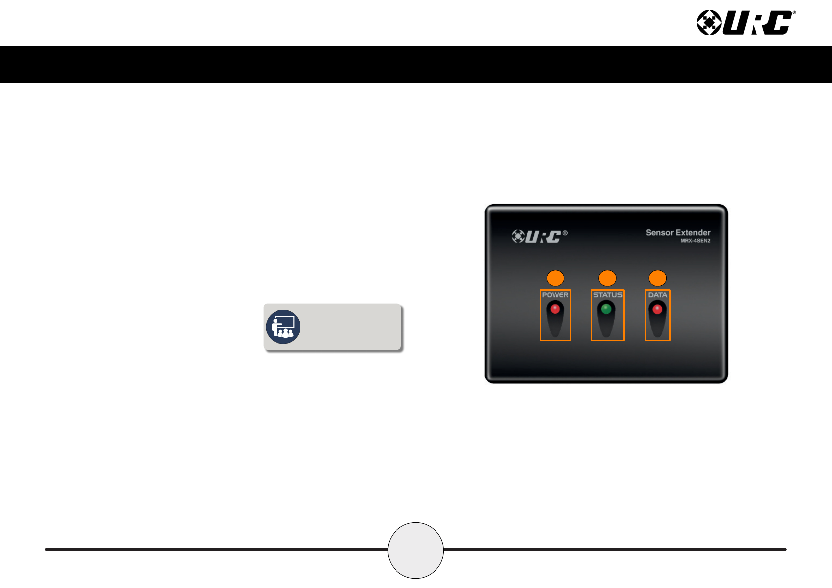
Front Panel Description ...................................................................................................................................................................................................................................................2
Rear Panel Description ....................................................................................................................................................................................................................................................3
Bottom Panel Description................................................................................................................................................................................................................................................4
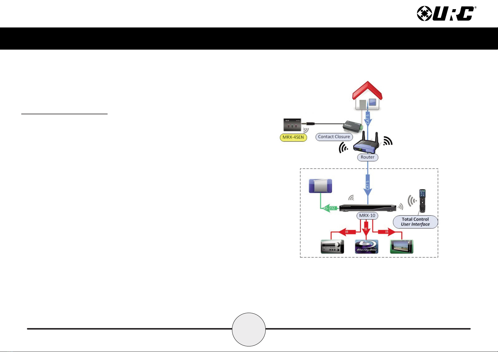
Installin the MRX-4SEN2 ...............................................................................................................................................................................................................................................5
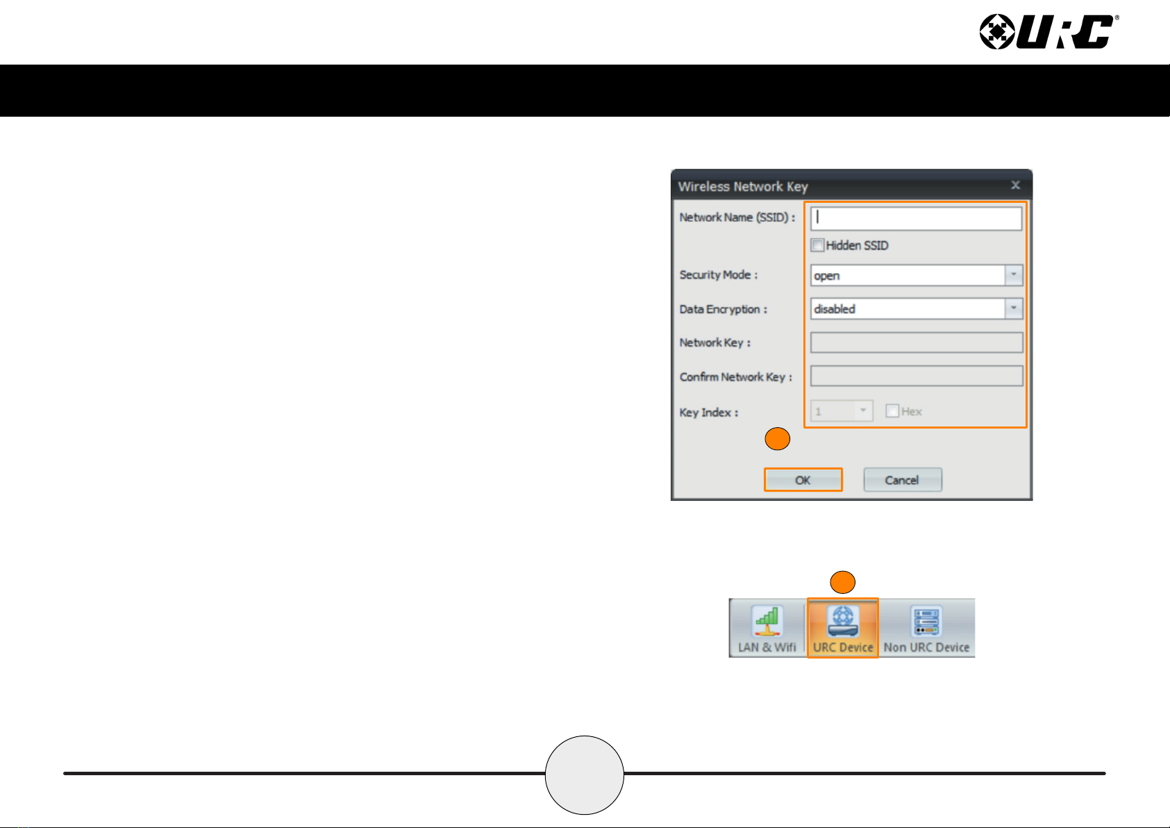
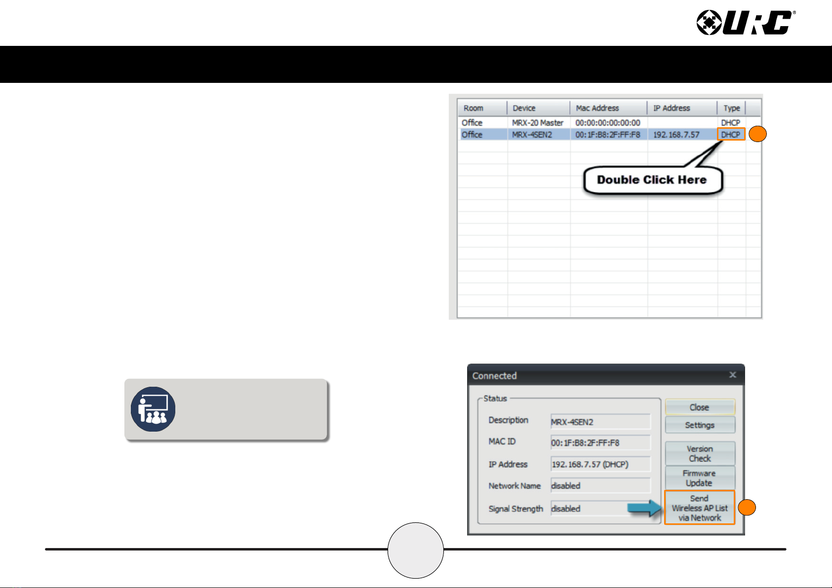
Wireless Setup ..................................................................................................................................................................................................................................................................6
Specifications ....................................................................................................................................................................................................................................................................9
Limited Warranty Statement............................................................................................................................................................................................................................................9

1
Total Control MRX-4SEN2
Owner’s Manual
Introduction
The MRX-4SEN2 Sensor Extender is designed to meet the needs of residential or
small commercial environments.
Only Total Control software, roducts, and user interfaces are su orted by this
owerful device.
Features and Benefits
• The MRX-4SEN2 utilizes the network (wired or wireless) for a more stable
communication to the Total Control System that is less susceptible to
interference and more reliable. This grants you the flexibility to install it
virtually anywhere in the roject.
• Add one or more MRX-4SEN2 throughout your home or ofce to
detect chan es in a connected sensor, which may be used to
tri er system events.
• The small size of the MRX-4SEN2 allows it to easily t behind equi ment or
into laces where a traditional base station would not.
Parts List
The MRX-4SEN2 Sensor Extender includes:
• 1x MRX-4SEN2 Sensor Extender
• 1x AC Power Ada ter
• 4x Mounting Screws
• Mounting Plate

2
Total Control MRX-4SEN2
Owner’s Manual
Front Panel Description
The front anel of the MRX-4SEN2 Sensor Extender dis lays the following information:
1. Power LED: Indicates the device has ower.
2. Status LED: Indicates three (3) ossible states:
■Green: Good signal strength.
■Red: Poor signal strength.
■Off: No connection.
3. Data LED: Indicates the device is transmitting IR data.
When connected via
Ethernet, the status LED
does not illuminate.
1 2 3

3
Total Control MRX-4SEN2
Owner’s Manual
Rear Panel Description
The rear anel of the MRX-4SEN2 Sensor Extender dis lays the following information:
1. DC 5V: Connect the su lied ower ada ter to this ort, the Power LED
becomes solid blue when the device has received ower.
2. Sensor Inputs: Connect the sensor’s 3.5mm lug to an available ort. The
following URC sensors, with their res ective model numbers, are
compatible with the MRX-4SEN2:
■Voltage Sensor SEN-VOLT
■Video Sensor SEN-VID
■Contact Closure Sensor SEN-CCLS
■Light Sensor SEN-LITE
■Current Sensor (Magnetic Field) SEN-CMF
■Audio Sensor SEN-AUD
3. Ethernet: If a wired connection is needed, this ort uses a standard Ethernet
(RJ-45) lug to communicate via the local area network (LAN).
12
3
To connect to Wi-Fi, an
initial Ethernet connection
must be made rst.

4
Total Control MRX-4SEN2
Owner’s Manual
Bottom Panel Description
The bottom anel of the MRX-4SEN2 Sensor Extender dis lays the following information:
1. Serial Number Sticker: The ZIGBEE Address (16 characters) identies this
wireless device when connected to the network.
2. MAC Number Sticker: The serial number, located at the bottom of the unit,
uniquely identies the roduct.
3. WPS (Wi-Fi Protected Setup): Functions with other wireless devices (routers,
wireless access oints, etc.) to rovide a simplified method of connection to the
network. Press this button in conjunction with the WPS button found on your other
wireless devices to establish.
4. Reset Button: Turns the unit OFF then ON again, and reconnects to the network.
2
4
1
3

5
Total Control MRX-4SEN2
Owner’s Manual
Installin the MRX-4SEN2
The MRX-4SEN2 Sensor Extender can be installed almost anywhere in the home.
Once hysically installed, it requires pro rammin by a certified URC inte rator
in order to function ro erly.
Connect the 3.5mm sensor lug to the rear of the MRX-4SEN2. When a chan e in
the sensor’s state is detected, the MRX-4SEN2 sends a signal to the MRX Advanced
Network System Controller and tri ers a series of commands.
This home network exam le showcases a volta e sensor connected to the home’s
doorbell and the MRX-4SEN2. Whenever the door bell is pressed, a signal is sent
over URC’s RF 2.4GHz to the MRX Advanced Network System Controller. The MRX
unit tri ers a series of commands or an event to gain your attention. A
rogrammed event, such as Watch Movie/TV, may ause the movie, mute the audio
and dis lay the front door’s video camera.

6
Total Control MRX-4SEN2
Owner’s Manual
Wireless Setup
The key feature added to the MRX-4SEN2 is adding Wi-Fi connectivity to an already
brilliant sensor ex ander. Wi-Fi connection makes it sim le to install the device in
difcult to reach locations of the home.
1. Go to Step 6: Network Setup and select Add New.
1
To connect to Wi-Fi, an
initial Ethernet connection
must be made rst.

7
Total Control MRX-4SEN2
Owner’s Manual
2
2. Fill out the wireless network information in the Wireless Network Key
window. Select OK when nished.
3. Select Save, located below 2. LAN Wireless Networks.
4. Select URC Device from the sub-menu in Step 6.
5. Discover the MRX-4SEN2 using the method for all URC network devices.
4

8
Total Control MRX-4SEN2
Owner’s Manual
6
6. Highlight the MRX-4SEN2 and double-click on the area that reads DHCP.
7. Select Send Wireless AP List via Network.
8. Un lug the Ethernet cable from the back of the MRX-4SEN2 unit.
The MRX-4SEN2 connects to Wi-Fi
automatically after the Wireless AP
list has been downloaded and the
Ethernet cable has been removed.
7

9
Total Control MRX-4SEN2
Owner’s Manual
Specifications
Sensor: Four sensor orts su ort Video, Current, Contact Closure,
Ambient Light, Audio, and Voltage sensors from URC.
Network: One 10/100/1000M RJ45 Ethernet ort (two LED indicators)
RF Ran e (Radio Frequency): 50 to 100 feet, de ending u on the
environment
RF Frequency: 2.405 ~ 2.480 GHz
Wei ht: 2.98oz
Size: 3.74” X 2.7” X 1.1”
Power: 12V DC 1A
Limited Warranty Statement
htt s://www.urc-automation.com/legal/warranty-statement/
End User A reement
The terms and conditions of the End User Agreement available at
htt s://www.urc-automation.com/legal/end-user-agreement/ shall a ly.
Federal Communication Commission Interference Statement
This equi ment has been tested and found to com ly with the limits for a Class B
digital device, ursuant to art 15 of the FCC Rules. These limits are designed to
rovide reasonable rotection against harmful interference in a residential installation.
This equi ment generates, uses and can radiate radio frequency energy and, if not
installed and used in accordance with the instructions, may cause harmful interference
to radio communications. However, there is no guarantee that interference will not
occur in a articular installation. If this equi ment does cause harmful interference to
radio or television rece tion, which can be determined by turning the equi ment off
and on, the user is encouraged to try to correct the interference by one more of the
following measures:
• Reorient or relocate the receiving antenna.
• Increase the se aration between the equi ment and receiver.
• Connect the equi ment into an outlet on a circuit different from that to which
the receiver is connected.
• Consult the dealer or an ex erienced radio/TV technician for hel .

10
Total Control MRX-4SEN2
Owner’s Manual
Re ulatory Information to the User
• CE conformity Notice Products with “CE” marking com ly EMC Directive
2014/30/EU issued by the commission of the Euro ean Community.
1. EMC Directive
• Emission
• Immunity
• Power
• Declaration of Conformity
“Hereby, Universal Remote Control Inc. declares that this MRX-4SEN2 is in
com liance with the Essential requirements.”
Warnin !
The manufacturer is not res onsible for any Radio or TV interference caused by
unauthorized modications to this equi ment.
Changes or modications not ex ressly a roved by the manufacturer could void the
user's authority to o erate the equi ment.
Table of contents
Other URC Extender manuals