Urrea GRUPO URREA 2354 User manual

Arrancador Remoto de Motor
Remote Starter Switch
MANUAL USUARIO / USER’S MANUAL
2354
ESPAÑOL / ENGLISH
ADVERTENCIA: Antes de usar este producto, lea este manual y siga
todas las reglas de seguridad e instrucciones de operación.
WARNING: Before using this product, read this manual and follow all safety rules
and operational instructions.

Arrancador Remoto de Motor 2354
2
ESPAÑOL
INSTRUCCIONES PARA EL INTERRUPTOR DE ARRANQUE
ADVERTENCIA:
Antes de conectar el interruptor de arranque
remoto, poner la palanca de cambio de ve-
locidades en “Park” para las transmisiones
automáticas o en “Neutral” para las transmisiones ma-
nuales y aplicar el freno de emergencia.
Nota: Es muy importante seguir las instrucciones en el
orden que se da a continuación.
PROCEDIMIENTO DE INHABILITACION
1. Inhabilitar el sistema de encendido como se descri-
be en la sección “Procedimientos de inhabilitación de
encendido”, de acuerdo al tipo de vehiculo que se esté
probando.
PROCEDIMIENTO DE CONEXIÓN
2. Conectar el interruptor de arranque remoto como se
indica en la sección de “conexiones del arrancador”.
Tener mucho cuidado cuando se haga esta conexión,
pues hay voltaje de batería presente en el solenoide o
en el revelador del arrancador y podrían sufrir lesiones
como resultado de un cortocircuito de los conductores.
3. Poner la llave del contacto en posición “ON” (abierto)
antes de usar el interruptor de arranque remoto.
PRECAUCIÓN:
Si el vehiculo tiene un indicador de motor
“HOT”(CALIENTE), se podría dañar el circui-
to de la luz de prueba si se energiza el inte-
rruptor de arranque remoto estando la llave de contacto
en posición “OFF” (cerrado)
OFF
ONACC
START
4. Después de conectar apropiadamente el interruptor
de arranque remoto, oprima el botón. El motor debe de
arrancar.
5. Después de retirar el interruptor de arranque remoto,
reconectar los conductores que fueron desconectados
durante el procedimiento de inhabilitación del encendido.
Los diagramas siguientes ilustran cinco de las confi-
guraciones más comunes del relevador y solenoide de
arranque y el método de conexión del arrancador remo-
to de motor. Identifique el sistema que usted tiene con
uno de los diagramas y siga las instrucciones individua-
les cuidadosamente.
PRECAUCIÓN:
Siempre hay voltaje de batería presente en
los terminales del solenoide o del relevador
de arranque y podría causar lesiones si llega-
ran a conectarse a tierra mediante herramientas, alam-
bres, relojes o pulseras.

Arrancador Remoto de Motor 2354
3
ESPAÑOL
CONEXIONES DEL ARRANCADOR REMOTO
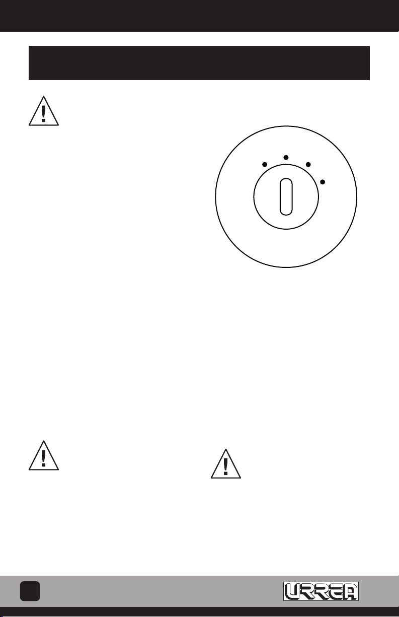
RELEVADOR DEL ARRANCADOR: FORD
Este relevador puede tener tres o cuatro terminales: dos grandes y uno
o dos pequeños. Retire los cables conectados a la terminal pequeña, si
sólo presenta una terminal pequeña. Si están presentes dos terminales
pequeñas, retire los cables de la terminal pequeña marcada “S”. Conecte
una de las puntas tipo caimán del Interruptor del Arrancador Remoto a la
terminal pequeña descubierta (donde los cables solamente fueron remo-
vidos) y la otra punta tipo caimán del Interruptor del Arrancador Remoto
a la terminal de la Batería del relevador. Encienda el motor presionando el
Interruptor del Arrancador Remoto. (FIG. 1)
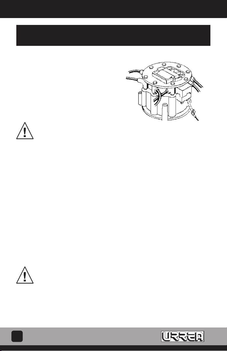
RELEVADOR DEL ARRANCADOR: CHRYSLER
Retire el conector que tiene la forma de “Y” del relevador como se mues-
tra en la Figura 2. La terminal debe permanecer conectada en la esquina
derecha inferior de relevador y el otro conector debe permanecer conec-
tado a la terminal del “SOLENOIDE”. Conecte una punta tipo caimán del
arrancador remoto a la terminal “EGR” del relevador y la otra punta tipo
caimán del arrancador remoto al poste positivo (+). De la batería. Encien-
da el motor presionando el Interruptor del Arrancador Remoto. (FIG. 2)
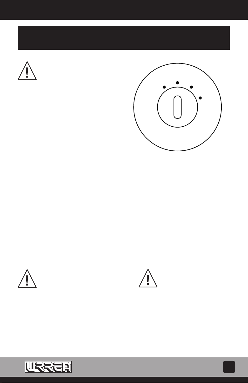
RELEVADOR DEL ARRANCADOR: AUTOMOVILES CHRYSLER K
Remueva el cable en forma de “U” de la terminal 5 del relevador como se
muestra en la Figura 3. La terminal debe permanecer conectada a la parte
superior de la terminal 3 del relevador, sin embargo, conecte una de las
puntas tipo caimán del arrancador en la terminal 3 del relevador y la otra
punta tipo caimán del arrancador en el poste de la batería POSITIVO (+)..
Encienda el motor presionando el botón del Arrancador Remoto (FIG. 3)
CONECTOR DE DIAGNOSTICO: GENERAL MOTORS
Inserte las terminales (no incluídas) en cavidades 1,6 y 8 del Conector
de Diagnóstico como se muestra en la Figura 4. Conecte un cable de
puente de la terminal 6 a la tierra del motor. Conecte una de las pun-
tas tipo caimán del Interruptor del Arrancador Remoto a la terminal 1
del Conector de Diagnóstico y otra punta del Interruptor del Arranca-
dor Remoto a la terminal 8 del Conector de Diagnóstico como se mues-
tra. Poner en marcha presionando el botón del Arrancador Remoto.
NOTA: Este conector de diagnóstico por lo general es localiza-
do sobre el lado del conductor en el compartimiento del mo-
tor. No lo confunda con el conector de diagnóstico de aire
acondicionado que esta sobre el lado de pasajeros. (FIG. 4)
SOLENOIDE DEL ARRANCADOR: GENERAL MOTORS
Conecte una punta tipo caimán del interruptor del arrancado remoto a la
terminal pequeña del solenoide marcada en “S” y la otra punta tipo caimán
del interruptor al cable de la batería como se muestra en la imagen. En-
cienda el motor presionando el Interruptor del Arrancador Remoto. (FIG. 5)
FORD
Fig. 1
CHRYSLER
Fig. 2
CHRYSLER K CARS
Fig. 3
GENERAL MOTORS
Fig. 4
GENERAL MOTORS SELENOIDE
Fig. 5

Arrancador Remoto de Motor 2354
4
ESPAÑOL
PROCEDIMIENTO DE INHABILITACIÓN DE ALTA ENERGÍA DE IGNICIÓN
EN GENERAL MOTORS
Cuando se hagan pruebas del sistema de diagnóstico
en vehiculo General Motors equipados con encendido
de alta energía de ignición (HEI), se puede prevenir el
arranque del motor de la siguiente manera.
SISTEMA CON BOBINA EN LA TAPA DEL
DISTRIBUIDOR
Desconectar el cable primario de la Terminal BAT que
se encuentra dentro de la tapa del distribuidor.
PRECAUCION:
La Terminal del tacómetro NUNCA debe co-
nectarse a tierra en la tapa de distribuidor pues
se dañaría el módulo del distribuidor. (FIG. 6)
SISTEMA CON BOBINA SEPARADA
Quitar el conector de la bobina (primario) y el cable de
alta tensión de la Terminal secundaria de la bobina. Co-
nectar un cable puente entre la Terminal secundaria de
la bobina y una puesta a tierra en el motor.
(FIG. 7)
HEI CON CONECTOR DE DIAGNOSTICO ELECTRICO
Insertar la Terminal del conector de diagnóstico GM en
la Terminal no. 6 del conector de diagnóstico eléctri-
co. Conectar un cable puente entre esta Terminal y una
buena puesta a tierra.
PRECAUCION:
La Terminal del tacómetro NUNCA debe co-
nectarse a tierra en la tapa de distribuidor pues
se dañaría el módulo del distribuidor. (FIG. 8)
Fig. 6
Fig. 7
Fig. 8

Remote Starter Switch 2354
5
ENGLISH
INSTRUCTIONS FOR REMOTE STARTER SWITCH
WARNING:
Before connecting the Remote
Starter Switch, set the transmission
gear lever in the “Park” position for
automatics or “Neutral” position for manual
transmissions and engage the emergency
brake.
NOTE:
It is important to follow the instructions
in the order shown below.
DISABLING PROCEDURE
1. Disable the ignition system as described
under the “Ignition Disabling Procedures”
Section as applies to the type of vehicle
under test.
CONNECTION PROCEDURE
2. Connect the Remote Starter Switch as
shown in the “Connection Remote Starter”
Section. Exercise care when making this
connection because battery voltage is
present at the solenoid or starter relay and
injury could result by shorting the leads.
3. Turn the ignition switch to the “ON”
position before using the Remote Starter
Switch.
CAUTION:
If the vehicle is equipped with an
engine “HOT” indicator, the lamp
test circuit which is in the ignition
system could be damaged if the remote
starter switch is energized with the ignition
switch in the “OFF” position.
OFF
ONACC
START
4. After the Remote Starter Switch has been
properly connected, push the button. The
engine should crank over.
5. After removing the Remote Starter Switch,
reconnect the leads that were disconnected
during the “Ignition Disabling Procedure”
Section.
The following diagrams illustrate five of the
most common starter relay and solenoid
arrangements and the method of connection
to the remote starter switch. Match the
system you have to one of the diagrams and
follow the individual instructions carefully.
CAUTION:
Battery voltage is always present
at the starter relay or solenoid
terminals and could cause
personal injury if shorted to ground through
tools, wires or wristwatch.

Remote Starter Switch 2354
6
ENGLISH
FORD
Fig. 1
CHRYSLER
Fig. 3
CHRYSLER
Fig. 4
CHRYSLER
Fig. 5
CONNECTION REMOTE STARTER
STARTER RELAY : FORD
This relay may have three or four terminals: two large ones and one or
two small ones. Remove the wires connected to the small terminal if
only one small terminal is provided. If two small terminals are present,
remove the wires from the small terminal marked “S”. Connect one lead
of the Remote Starter Switch to the bare small terminal (where the wires
were just removed) and the other lead of the Remote Starter Switch to
the Battery Terminal of the relay. Crank the engine by depressing the
Remote Starter Switch. (FIG. 1)
STARTER RELAY: CHRYSLER
Remove the “Y” shaped connector from the relay as shown in Figure 2.
The single terminal connector must remain connected at the lower right
hand corner of the relay and the other single terminal connector must
remain connected to the “SOL” relay terminal as shown. Connect one
lead of the Remote Starter Switch to the ‘EGR’ terminal of the relay and
the other lead of the Remote Starter Switch to the Positive (+) post of the
battery.CranktheenginebydepressingtheRemoteStarterSwitch.(FIG.2)
STARTER RELAY: CHRYSLER K CARS
Remove the “U” shaped 5 terminal connector from the relay as shown
in Figure 3. The single terminal connector must remain connected to the
top of terminal 3 of the relay, however, connect one lead of the Remote
Starter Switch to the bottom of terminal 3 on the relay and the other lead
of the Remote Starter Switch to the POSITIVE (+) post of the battery.
Crank the engine by depressing the Remote Starter Switch. (FIG. 3)
DIAGNOSTIC CONNECTOR: GENERAL MOTORS
Insert spade terminals (not supplied) into cavities 1,6 and 8 of the
Diagnostic Connector as shown in Figure 4. Connect a jumper wire from
terminal 6 to engine ground. Connect one lead of the Remote Starter
Switch to terminal 1 of the Diagnostic Connector and the other lead of
the Remote Starter Switch to terminal 8 of the Diagnostic Connector as
shown. Crank the engine by depressing the Remote Starter Switch.
NOTE:
This diagnostic connector is usually located on the driver’s side
in the engine compartment. Do not confuse it with Air Conditioning
diagnostic connector on the passenger side. (FIG. 4)
STARTER SOLENOID: GENERAL MOTORS
Connect one lead of the Remote Starter Switch to the small terminal
of the solenoid marked “S” and the other lead of the Remote Starter
Switch to the heavy battery cable as shown. Crank the engine by
depressing the Remote Starter Switch. (FIG. 5)
CHRYSLER
Fig. 2

Remote Starter Switch 2354
7
ENGLISH
GENERAL MOTORS HIGH ENERGY IGNITION DISABLING POCEDURES
When performing Diagnostic System tests
on General Motors vehicles equipped with
High Energy Ignition (HEI), the engine can be
prevented from starting as follows.
SYSTEM WITH COIL IN DISTRIBUTOR CAP.
Disconnect primary wire from the BAT
terminal on the distributor cap.
CAUTION:
The tachometer terminal must NEV-
ER be connected to ground at the
distributor cap as damage to the
distributor module can result. (FIG. 6)
SYSTEMS WITH SEPARATE COIL
Remove the coil connector (primary) and
the high-tension wire from coil secondary
terminal. Connect jumper wire between coil
secondary terminal and ground on engine.
(FIG. 7)
HEI WITH ELECTRICAL DIAGNOSTIG CONNECTOR
Insert the GM Diagnostic Connector Terminal
in terminal No. 6 of Electrical Diagnostic
Connector. Connect jumper wire between
this terminal and a good ground
CAUTION:
The tachometer terminal must
NEVER be connected to ground at
the distributor cap, as damage to
the distributor module can result. (FIG. 8)
Fig. 6
Fig. 7
Fig. 8

SELLO DEL DISTRIBUIDOR
FECHA / /
www.urrea.com
Póliza de garantía. Este producto está garantizado por URREA HERRAMIENTAS PROFESIONALES, S.A. DE C.V., km 11,5
Carr. A El Castillo, 45680 El Salto, Jalisco. UHP900402Q29, Teléfono 01 33 3208-7900 contra defectos de fabricación y
mano de obra con su reposición o reparación sin cargo por el período de 100 años. Para hacer efectiva esta garantía,
deberá presentar el producto acompañado de su comprobante de compra en el lugar de adquisición del producto o
en el domicilio de nuestra planta mismo que se menciona en el primer párrafo de esta garantía. En caso de que el
producto requiera de partes o refacciones acuda a nuestros distribuidores autorizados. Los gastos que se deriven para
el cumplimiento de esta garantía serán cubiertos por Urrea Herramientas Profesionales, S.A. de C.V.
Esta garantía no será efectiva en los siguientes casos:
a).- Cuando la herramienta se haya utilizado en condiciones distintas a las normales.
b).- Cuando el producto hubiera sido alterado de su composición original o reparado por personas no autorizadas por
el fabricante o importador respectivo.
This product has a lifetime warranty by Urrea Herramientas Profesionales S.A. de C.V. against any manufacturing
defect, with its repair or replacement during its life expectancy. The warranty is not applicable if the product does not
show the URREA brand, if the product is worn out by its daily use, shows signs of abuse, damage, its original compo-
sition has been altered, or specifies a different warranty. In order to make the warranty effective, the product must be
taken to the company or to the place of purchase along with its receipt.
IMPORTADO POR / IMPORTED BY: URREA HERRAMIENTAS PROFESIONALES S.A. DE C.V. km 11,5 Carretera a El Castillo,
C.P. 45680 El Salto, Jalisco, México R.F.C. UHP900402Q29 Tel. 01 (33) 3208-7900 Hecho en Taiwán/ Made in Taiwan
Table of contents
Languages: