Urrea 23621 User manual

23621
ATENCIÓN: Lea, entienda y siga las instrucciones de seguridad contenidas en este
documento, antes de operar esta herramienta.
WARNING: Read, understand and follow the safety rules in this document, before operating this tool.
Bomba Manual para Grasa con Cubeta
Manual Bucket Grease
Manual de Usuario y Garantía
User’s Manual and Warranty

3
ESPAÑOL
SEGURIDAD PERSONAL
• La bomba deberá ser operada por personal
capacitado.
• Siempre utilice lentes de seguridad o Goggles.
• Siempre utilice guantes cuando opere la
bomba.
• No apunte hacia usted o hacia los demás la
terminal de descarga, ya que hay riesgo de
inyección a la piel o a los ojos.
• No permita que ninguna parte de su cuerpo
entre en contacto con los fluidos que está
operando.
• Antes de utilizar la bomba, verifique que no
existan señales de deterioro, escurrimiento o
conexiones sueltas. Si la manguera esta suelta,
dañada o desgastada, reemplacela de inmediato.
• En caso de accidente, busque ayuda medica de
inmediato. No trate de atenderse por sí mismo.
• Utilice solo piezas originales de repuesto.
• No fume mientras utilice la bomba o cerca de
ella.
• No utilice la bomba cerca de alguna fuente de
chispa o flamable, etc…
CARACTERÍSTICAS
• Alto Volumen – Bomba de grasa de alta
presión, ideal para engrasar equipos terrestres,
equipo agrícola, aplicaciones automotrices y
en cualquier situación en la que se requiera
aplicar de manera rápida un volumen de grasa
importante.
• Bomba con cabezal de fundición de aluminio
con válvula acoplada a la cabeza de la bomba.
• Manija de ajuste variable que permite el uso de
la grasa con una variedad de viscosidad.
• Cubierta del tambor, cubeta y reposa pie,
construidas en acero.
• Manija de levante integrada a la cubeta.
• Revestimiento de Goma adherido a la placa
seguidora para forzar el aire atrapado en la
grasa.
• Incluye Manguera de caucho de 2m x ¼” de
Diámetro interno (SAE 100 R2), que cuenta con
manija de acero, extensión y cople.
• Eslabón giratorio a la salida de la bomba, para
un mejor desempeño de la manguera.
• La bomba ofrece hasta 4000 PSI (275 BAR).
• Distribuye hasta 9 gms por bombeo (1oz. Por
cada 3 bombeos)
• Algunos modelos cuentan con ruedas para su
fácil desplazamiento.
INSTRUCCIONES DE OPERACIÓN
• Esta es una bomba operada manualmente y
debe ser únicamente por fuerza manual. Jamás
utilice el pie, martillos, tubos, etc. Para operar la
bomba.
• Para asegurarse que la bomba no se levante
durante su uso, mantenga un pie en el posa pie
provisto en la cubeta. Nunca ponga el pie sobre
la cubierta del tambor.
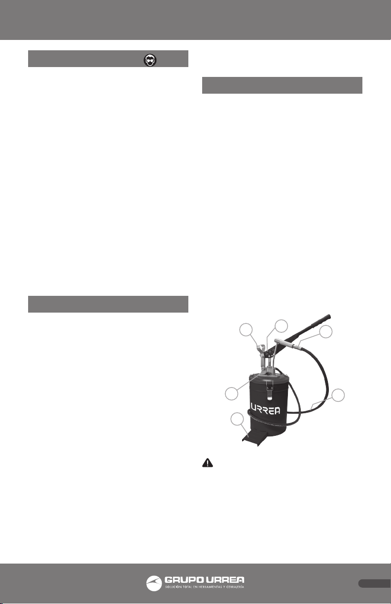
CONOZCA SU HERRAMIENTA
Antes de intentar usar este producto,
familiarícese con todas sus características de
operación y requerimientos de seguridad.
1. MANIJA PARA AJUSTE VARIABLE
2. ADAPTADOR CON COPLE PARA RELLENO DE
GRASA.
3. VALVULA DE ESCAPE DE AIRE.
4. MANGUERA DE ALTA PRESIÓN.
5. PLACA PIE DE APOYO.
6. MANIJA DE LEVANTE.
2
4
3
5
61
ADVERTENCIA: Saque la bomba de su
empaque y examinelo cuidadosamente. No tire
el empaque hasta que todas las partes hayan
sido examinadas.
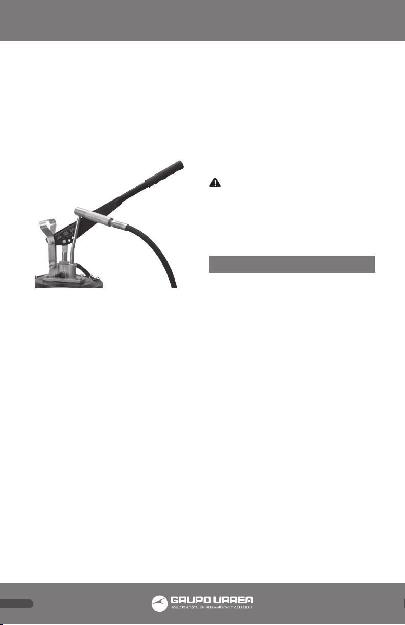
INSTALANDO LA MANIJA DE AJUSTE
• Saque el juego de bomba de la caja.
Adicionalmente a la unidad de bomba, habrá
una manija por separado.

4
ESPAÑOL
• Ensamble la manija con el eslabón de enlace.
• Tiene la opción de 3 hoyos en los cuales el
pistón de la bomba pueden ensamblarse.
1. Posición más cercana al eslabón de enlace:
El ensamble del pistón a este orificio permite a
la grasera la opción de Alta presión que ofrece
hasta 4000 PSI (275 BAR) y distribuye 4 gms de
grasa por bombeo. Esta posición es sugerida
cuando se utiliza grasa espesa.
2. Posición más alejada del eslabón de enlace: El
ensamble del pistón a este orificio permite a la
grasera distribuir un alto volumen de grasa de
hasta 9 gms por bombeo a una presión de 2000
PSI. Esta opción es recomendada para cuando se
trabaja con grasa poco espesa.
3. Posición intermedia: El ensamble del pistón a
este orificio permite a la grasera distribuir hasta
3000 PSI (206BAR) de presión y distribución.
7 gms de grasa por bombeo. Esta posición es
recomendada para uso general.
• Ahora abra las 3 abrazaderas de la cubierta y
remueva la cubierta del tambor de la grasera.
• Limpie el interior del barril de grasa,
asegurándose de que no existan particular
extrañas.
• Ponga grasa limpia en el tambor. No lo rellene
hasta el tope, si no hasta el limite marcado como
máximo. Llénelo hasta la posición marcada en el
tambor.
• Ahora coloque la placa seguidora con
revestimiento de Goma sobre la grasa y empújelo
hacia abajo. Siga empujando hasta que la grasa
comience a salir por el orificio central. Las orillas
de caucho deben de rozar contra las paredes
interiores de la cubeta de acero.
• Coloque nuevamente la cubierta de acero
sobre la cubeta. Cuando haga este paso, debe de
insertar la bomba de acero en el orificio central
del plato. Coloque la tapa del tambor y cierre las
3 abrazaderas.
• Sacuda el tambor un poco para asentarlo y
comprimir la grasa.
• Empiece a operar la manija, hasta que la grasa
empiece a fluir fuera del cople de la manguera.
Esto debe tomar por lo menos 20 bombeos
cuando se utilice la bomba por primera vez.
• Si después de este proceso la bomba no
dispensa grasa, entonces agite un poco más
la cubeta para comprimir el aire en el interior.
Adicionalmente abra la válvula de escape de aire
en la cabeza de la bomba y opere la manija hasta
que la grasa comience a salir de la válvula. De
esta forma cualquier aire atrapado es liberado.
Una vez que la grasa comience a salir, cierre la
válvula.
ADVERTENCIA: Se recomienda que cualquier
reparación o servicio sean realizados en un
centro de servicio calificado.
MANTENIMIENTO GENERAL
El uso de grasa limpia le dará años de servicio
libre de problemas. Asegúrese de que la grasa
que utilice no este contaminada.
SOLUCIONADOR DE PROBLEMAS
La bomba no dispensa grasa:
1. Burbujas de aire/ aire atrapado: Agite un
poco más la cubeta para comprimir el aire en
el interior. Adicionalmente abra la válvula de
escape de aire en la cabeza de la bomba y opere
la manija hasta que la grasa comience a salir de
la válvula
2. La placa seguidora se atoró: Abra la cubierta
del tambor- re-inserte la placa de seguimiento y
coloque nuevamente la cubierta de acero sobre
la cubeta. Cuando haga este paso, debe de
insertar la bomba de acero en el orificio central
del plato. Coloque la tapa del tambor y cierre las
3 abrazaderas.
3.Grasa muy espesa, generalmente en clima frío:
Caliente un poco la cubeta de grasa.
4.Contaminantes causando bloqueo: Desarme la
bomba y remueva el bloqueo.
La grasera gotea de la parte superior: Remplace
los empaques. Esta es una parte que se desgasta
con el uso y que deben ser remplazadas.

5
ENGLISH
PERSONAL SAFETY
• Pump should be operated by trained personnel
only
• Always wear Safety Goggles when using the
pump
• Always use Gloves when using the pump
• Do not point the discharge end towards
yourself or anyone as there is potential hazard
for injection into skin / eyes
• Never allow any part of the body to come in
contact with the operating fluid
• Before operating the pump , check hose for
signs of wear , leaks or loose connections. If hose
is weak , worn or damaged, replace the hose
immediately
• Incase of an accident, immediately seek
emergency medical attention. Do not try to treat
the injury yourself
• Use only genuine factory parts for repair
• Do not smoke when using / near the pump
• Do not use the pump near a source of spark /
open flames etc.
FEATURES
• High volume - High pressure grease pump,
ideal for greasing earth moving & agricultural
equipment, automotive
applications & anywhere where quick volume
greasing is required
• Aluminum Die Cast Pump Head with Air
Release Valve fitted on the Pump Head
• Variable Handle Setting allows convenient use
of the pump with grease of varying viscosity
• Steel Drum Cover, Bucket & foot Rest
• Built in Lift handle
• Rubber Lining Follower Plate for forcing out
trapped air in grease
• Includes 2 m x ¼” ID High pressure rubber hose
(SAE 100 R2) , fitted with steel handle , extension
& coupler
• Swivel Adapter at Pump outlet for convenient
handling of hose
• Pump develops upto 4000 PSI (275 BAR)
•Deliversupto9gmsperstroke(1oz.per3strokes)
• Select models are with wheels for ease of use
OPERATION INSTRUCTIONS
• This is a Hand Operated Pump & must only be
used by Hand Force. Never use foot , hammer ,
pipe etc. to operate the pump.
• To ensure that pump does not lift when in
use, keep one foot onto the Foot Rest provi-
ded. Never keep your foot onto the Drum Cover.
KNOW YOUR TOOL
Before taking this product, familiarize yourself
with all operating features and safety require-
ments.
1. VARIABLE HANDLE SETTING
2. PISTOL HANDLE FITTED WITH STEEL GREASE
EXTENSION.
3. AIR RELEASE VALVE.
4. HIGH PRESSURE HOSE.
5. STEEL BUCKET WITH FOOT REST.
6. LIFT HANDLE.
2
4
3
5
61
WARNING: Remove the pump from its
packaging and check all parts. Do not discard
the packaging until all parts has been examined.
INSTALLING ADJUSTMENT HANDLE
• Remove the pump assembly from the box .In
addition to the pump unit , there would be a
Lever Handle placed separately.
• Assemble the Lever Handle with the Connec-
ting Link.
• You have a choice of 3 holes into which the
pump piston could be assembled.
1. Hole Closest to the Connecting Link: Assembly
of the piston into this hole allows the pump to
develop High pressure upto 4000 PSI (275 BAR) &
deliver 4 gm of grease per stroke. This position is
suggested when using thick grease.
6
ENGLISH
2. Hole Farthest from the Connecting Link: As-
sembly of piston into this hole allows the pump
to deliver high volume of grease upto 9 gms per
stroke & a pressure upto 2000 PSI. This position is
ideal when using thin grease.
3. Middle Hole: Assembly of piston into this hole
allows the pump to develop upto 3000 PSI (206
BAR) pressure & deliver approx. 7 gms of grease
per stroke. This position is good for all general
purpose applications.
• Now open the 3 Cover Clamps & remove the
drum cover assembly from the grease drum.
• Clean the inside of the grease drum , ensuring
that no foreign particles stay inside.
• Transfer clean grease into the grease drum.
Do not fill the drum till the top, but only till the
Max. Fill Position marked on the drum.
• Now place the Rubber Lining follower plate
onto the grease & push it down. Keep pushing
it till grease starts coming out of the centre hole.
The rubber edges of the follower plate must
rub against the inside walls of the steel bucket.
• Place the Drum cover assembly back onto the
Grease bucket. When doing so, the steel pump
must be inserted from the centre hole in the fo-
llower plate. Place the drum cover on the edges
of the Grease drum & close all 3 Cover clamps Va-
riable Handle Setting High Pressure Setting De-
velops 4000 PSI with grease discharge of 4 gms
per stroke High Pressure High V lume Setting De-
velops 3000 PSI with grease discharge of 7 gms
per stroke Develops 2000 PSI with grease dischar-
ge of over 9 gms per stroke. Also useful for bulk
filling grease guns High Volume Setting
• Shake the drum a little so as to settle / compress
the grease inside
• Start operating the lever handle, till grease
starts flowing out of the coupler fitted at the
end of the hose. This
may take upto about 20 strokes when using the
pump for the first time
• If pump still does not dispense grease, then
shake the bucket a little more to compress the
Grease inside.
Additionally open the Air Release Valve on the
Pump Head & operate the lever handle till grea-
se starts
coming out of valve. This way any trapped air
gets released .Once grease starts coming out,
close the valve.
WARNING: It is recommended that any repairs
or service are provided at a qualified service center.
GENERAL MAINTENANCE
Using Clean Grease will give you years of trou-
ble free use. Make sure that Grease use is not
contaminated.
TROUBLESHOOTING
Pump does not Dispense Grease
1. Air Pockets / Trapped Air in Grease: Shake
the tray slightly to compress the air inside. Addi-
tionally open the air release valve on the pump
head and operate the handle until grease starts
to come out of the valve.
2. Follower plate got stuck: Open the drum cover
re-insert-monitoring plate and replace the steel
cover on the tray. When you do this step, you
must insert the steel bomb in the center hole
of the plate. Place the drum lid and close the 3
clamps.
3.Very Thick Grease, mainly in cold weather:
Warm the Grease Bucket a little.
4.Contaminants causing blockage: Dis-assemble
the pump to remove the blockage Grease leaks
from top of the pump head.
Grease leaks from top of the pump head
Worn Plunger Rod Seal Replace the seal: This is
a commonly wearing part & available as a spare
part.


Póliza de garantía. Este producto está garantizado por URREA HERRAMIENTAS PROFESIONALES, S.A. DE C.V., km 11,5 Carr. A El Castillo,
45680 El Salto, Jalisco. UHP900402Q29, Teléfono 01 33 3208-7900 contra defectos de fabricación y mano de obra con su reposición
o reparación sin cargo por el período de 100 años. Para hacer efectiva esta garantía, deberá presentar el producto acompañado de su
comprobante de compra en el lugar de adquisición del producto o en el domicilio de nuestra planta mismo que se menciona en el primer
párrafo de esta garantía. En caso de que el producto requiera de partes o refacciones acuda a nuestros distribuidores autorizados.
Los gastos que se deriven para el cumplimiento de esta garantía serán cubiertos por Urrea Herramientas Profesionales, S.A. de C.V. Esta
garantía no será efectiva en los siguientes casos:
a).- Cuando la herramienta se haya utilizado en condiciones distintas a las normales.
b).- Cuando el producto hubiera sido alterado de su composición original o reparado por personas no autorizadas por el fabricante o
importador respectivo.
This product has a lifetime warranty by Urrea Herramientas Profesionales S.A. de C.V. against any manufacturing defect, with its repair or
replacement during its life expectancy. The warranty is not applicable if the product does not show the URREA brand, if the product is worn
out by its daily use, shows signs of abuse, damage, its original composition has been altered, or specifies a different warranty. In order to
make the warranty effective, the product must be taken to the company or to the place of purchase along with its receipt.
SELLO DEL DISTRIBUIDOR
FECHA: / /
23621
Table of contents
Languages:
Other Urrea Water Pump manuals


Popular Water Pump manuals by other brands


DUROMAX
DUROMAX XP WX Series user manual

BRINKMANN PUMPS
BRINKMANN PUMPS SBF550 operating instructions

Franklin Electric
Franklin Electric IPS Installation & operation manual

Xylem
Xylem e-1532 Series instruction manual

Milton Roy
Milton Roy PRIMEROYAL instruction manual

STA-RITE
STA-RITE ST33APP owner's manual