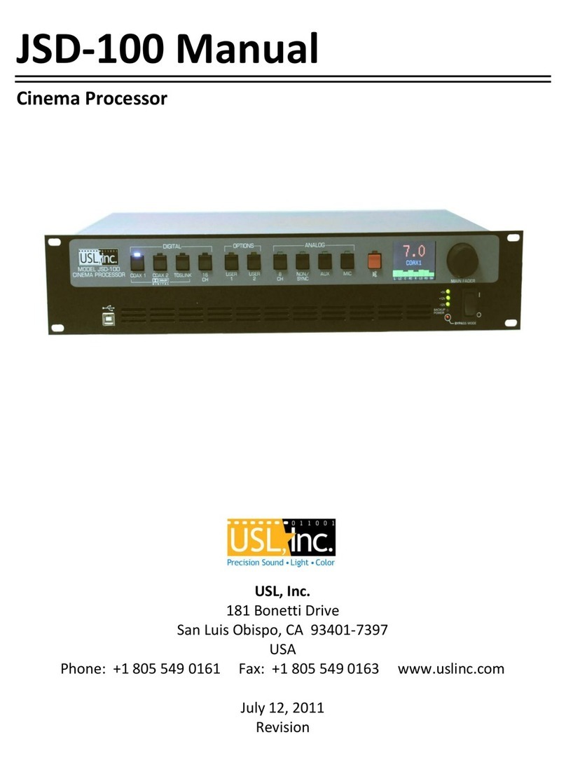
Usl JSD-100 User manual

Film-Tech
The information contained in this Adobe Acrobat pdf
file is provided at your own risk and good judgment.
These manuals are designed to facilitate the
exchange of information related to cinema
projection and film handling, with no warranties nor
obligations from the authors, for qualified field
service engineers.
If you are not a qualified technician, please make no
adjustments to anything you may read about in these
Adobe manual downloads.
www.film-tech.com

JSD100Manual
CinemaProcessor
USL,Inc.
181BonettiDrive
SanLuisObispo,CA934017397
USA
Phone:+18055490161Fax:+18055490163www.uslinc.com

Page2
OneYearLimitedWarranty
USL,Inc.warrantsthateachproductmanufacturedbyitwillbefreefromdefectsinmaterialand
workmanshipundernormalusageforaperiodofone(1)yearafteritspurchasenewfromanauthorized
dealer.Ourobligationunderthiswarrantyislimitedtorepairingorreplacinganyproductorcomponent
whichwearesatisfieddoesnotconformwiththeforegoingwarrantyandwhichisreturnedtoourfactory,
freightpaid,orservicedbyoneofourauthorizedcontractors.Theforgoingwarrantyisexclusiveandinlieuof
allotherwarranties,whetherexpressedorimplied.Suchwarrantyshallnotapplytoanyproductor
component(A)repairedoralteredbyanyoneotherthanUSL,Inc.oranauthorizedservicecontractor;(B)
tamperedwithoralteredinanywayorsubjectedtomisuse,negligenceoraccidentor(C)whichhasbeen
improperlyconnectedinstalledoradjustedotherthaninaccordancewithUSL,Inc.’sinstruction.

Page3
TableofContents
1. SafetyNotice Page 4
2. Re
g
ulator
y
Com
p
liance Pa
g
e5
2.1
2.2EquipmentClass
2.3DisposalandRecycling
3. SystemOverview Page 9
4. S
p
ecifications Pa
g
e10
5. Installation Pa
g
e12
5.1InitialPowerU
p
5.2SystemHardwareMounting,GroundingandVentilation
5.3RearPanelConnections
5.4AudioInputConnections
5.5AudioOutputConnections
5.6AutomationInterface
6. GraphicalUserInterfaceConfiguration Page 22
6.1GUIInstallation
6.2SetIPUtility
6.3JSD100Configuration
6.4Automation
6.5SystemMonitoring
6.6GUIViewsofMultipleJSD100s
7. ProductSupport Page 45
8. A
pp
endixA–AutomationCommands Pa
g
e46
9. A
pp
endixB–S
y
stemRestore Pa
g
e48

Page4
1. SafetyNotice
SafetyNotices
Reviewthefollowingsafetyprecautionstoavoidinjuryandpreventdamagetothisproduct.Toavoid
potentialrisk,usethisproductonlyasspecifiedandonlyforthepurposedescribedintheinstructionmanual.
ToAvoidFireandPersonalInjury:
xUsecorrectpowercable.Useonlythepowercableprovided.EnsurethattheACpoweroutletis
locatedneartheproductandiseasilyaccessible.
xUseacorrectlygroundedpowersource.Thepowersupplyearthgroundisestablishedthroughthe
groundconductorinthepowercable.Toavoidthepotentialofelectricshock,thegroundconductor
mustbecorrect.
xObservesourceratings.Toavoidriskoffireorelectricshock,thepowersourcemustbe100–240
VAC,50–60Hz.
xDonotoperatewithsuspectedfailures.Ifyoususpectthereisdamageormalfunctionwiththis
product,callthefactory.
xDonotattemptrepair.Onlyatrainedfactoryservicepersonisauthorizedtorepairthisproduct.
xDonotoperatethisproductnearheatsources.Thisproductshouldnotbelocatednearheat
sourcessuchasradiators,heatregisters,orstoves.
xProvideproperventilation.Theoperatingtemperaturerangeisbetween0ºCand40ºC.The
humidityrangeisbetween20%and80%,noncondensing.Thecoolingmethodisconvection.
xKeepproductsurfacescleananddry.Disconnectthepowercablefromthepowersourcebefore
cleaning.Donotuseliquidcleanersoraerosolcleaners.Useadampclothforcleaning.
xDonotpushobjectsintoopeningsofthisproduct.Neverinsertobjectsintotheproductthrough
openings.
xDonotoperateinwetordampconditions.
xDonotoperateinanexplosiveatmosphere.
xInspectthepowercableandallcablespriortouse.Confirmthatthepowercableandother
interconnectingcablesarefreefromdamage.

Page5
2.RegulatoryCompliance
EN609501
TheEN609501standardspecifiesthesafetydesignrequirementsthatreduceoreliminatetheriskof
personalinjurytoboththeproductuserandservicepersonnel.Thisproductisdesignedandtestedtomeet
thestandardsoftheInternationalElectrotechnicalCommission(IEC)EuropeanNormEN609501,IEC609501
(thestandardforinformationtechnologyequipmentincludingelectricalbusinessequipment).
LeRésumédelaSécuritégeneralEuropéen
Examinezlesprécautionsdelasécuritésuivanteséviterlablessureetprévenirledégâtàceproduit.Éviterle
risquepotentiel,utilisezceproduitseulementcommeaspécifiéetseulementcarlebutadécritdansle
manueld’instructions.
ÉviterFeuetBlessurePersonnelle
xUtilisezleCâbleduPouvoirCorrect.Utilisezseulementlecâbledupouvoirfourni.AssurezquelesAC
fontfonctionnerledébouchéestlocaliséprèsleproduitetestaccessiblefacilement.
xUtilisezuneSourceduPouvoirCorrectementFondée.
xLaterredumondedelaProvisionduPouvoirestétablieàtraversleconducteurmouludanslecâble
dupouvoir.Éviterlepotentieldechocélectrique,leconducteurmouludoitêtrecorrect.
xObservezdesEstimationsdelaSource.Pouréviterrisquedefeuouchocélectrique,lasourcedu
pouvoirdoitêtre220240VAC50Hz.
xN’opérezpasceProduitavecToutesClôturesOuvertesouEnlevez.
xÉvitezl’EnsembledecircuitsExposé.N’entreprenezpasouvrirlaProvisionduPouvoirparcequesa
certificationdelasécuritéseraitinvalidée.LaProvisionduPouvoirestunappareilscellénon
réparable.
xN’opérezpasaveclesÉchecsSuspects.Sivoussuspectezilyaledégâtoumalfonctionneravecce
produit,appelezl’usine.
xN’entreprenezpasRéparation.Seulementunepersonneduservicedel’usinecompétenteest
autoriséepourréparerceproduit.
xN’opérezpasceProduitSourcesdelaChaleurProches.Ceproduitnedevraitpasêtrelocalisé
desourcesdelachaleurprochestelqueradiateurs,registresdelachaleur,poêles,ouamplificateurs.
xFournissezVentilationAdéquate.Latempératuredufonctionnementdevraitêtreentre0°Cet40°C.
xL’humiditédevraitêtre20%et80%.Laméthoderefroidissanteestparconvectionetunventilateur
interne.
xGardezlesSurfacesduProduitNettoientetSec.
xDéconnectezlecâbledupouvoirdelasourcedupouvoiravantdenettoyer.N’utilisezpasde
nettoyeurs.liquidesoudenettoyeursdel’aérosolUtilisezuntissuhumidepournettoyer.
xNepoussezpasd’ObjetsDansOuvrirdeceProduit.
xJamaisobjetsdel’encartdansleproduitàtraversouvertures.
xN’opérezpasDanslesConditionsMouilléesouhumides.
xN’opérezpasDansuneAtmosphèreExplosive.
xPrévenezleRépandredesLiquidessurlesComposantsduSystème.
xInspectezlecâbledupouvoirettouslescâblesantérieuràusage.Confirmezquelecâbledupouvoir
etautresinterconnectantcâblessontlibresdedégât.
LeNiveaudelasécurité
L’EN60065niveauspécifieexigencesdudessindelasécuritéquiréduisentouéliminentlerisquedeblessure
personnelleàl’utilisateurduproduitetpersonnelduservice.Ceproduitestconçuetesttestépoursatisfaire
auxniveauxdel’ElectrotechnicalCommissionInternational(IEC)NormEuropéen(EN)60065(LeNiveaupour
MatérieldelaTechnologiedel’InformationquiInclutleMatérieldel’AffaireÉlectrique).

Page6
AllgemeineSicherheitZusammenfassungEuropäisch
ÜberprüfenSiediefolgendSicherheitVorkehrungen,VerletzungzuvermeidenundSchadenzudiesem
Produktzuverhindern.UmpotentiellesRisikozuvermeiden,benutzenSiediesesProduktnurals
vorgeschriebenhatundnurdennderZweckbeschriebinderBedienungsanleitung.
UmFeuerundPersönlicheVerletzungzuvermeiden:
xBenutzenSieKorrektesMachtKabel.BenutzenSienurdasMachtKabel,dasbereitgestelltwurde.
StellenSiesicher,daßderWECHSELSTROMMachtAbflußinderNähevomProduktgefundenwird
undleichtzugänglichist.
xBenutzenSieeineKorrektgeerdetMachtQuelle.DerMachtVersorgungErdeBodenwirddurchden
BodenSchaffnerimMachtKabelgegründet.DasPotentialelektrischenSchockszuvermeidenmuß
derBodenSchaffnerkorrektsein.
xBeobachtenSieQuelleKlassen.RisikovonFeueroderelektrischemSchockzuvermeidenmußde
MachtQuelle100sein240VAC5060Hz.
xOperierenSiediesesProduktmitIrgendwelchenGehegennicht,diegeöffnetwurden,oderentfernen
Sie.
xVermeidenSieUngeschütztenSchaltkreise.VersuchenSie,dieMachtVersorgungzuöffnennicht,
weilseineSicherheitZulassungungültiggemachtwerdenwürde.DieMachtVersorgungisteinnicht
reparierbaresluftdichtverschlosseneGerät.
xOperierenSiemitverdächtigtMißerfolgennicht.WennSieverdächtigen,gibtesSchadenoder
FunktionsstörungmitdiesemProdukt,rufenSiedieFabrik.
xVersuchenSiekeineReparatur.NureineerzogenFabrikDienstPersonwirdermächtigt,dieses
Produktzureparieren.
xOperierenSiediesesProduktNaheHitzeQuellennicht.DiesesProduktsolltekeinenaheHitze
QuellenwieHeizkörper,HitzeRegister,Herde,oderVerstärkergefundenwerden.
xStellenSieRichtigeBelüftungbereit.DieoperierendTemperatursolltezwischen0°Cund40°C.Die
Luftfeuchtigkeitsolltesein20%und80%.DieerfrischendMethodeistdurchKonvektionundeinen
innererenFächer.
xBleibenSie,ProduktOberflächenreinigenundTrocken.TrennenSiedasMachtKabelvonderMacht
QuellevordemReinigen.BenutzenSiekeineflüssigeReinigeroderAerosolReiniger.BenutzenSie
einenklammenStofffürdasReinigen.
xSchiebenSiekeineGegenständeInsÖffnenvondiesemProdukt.NieBeifügungGegenständeins
ProduktdurchÖffnungen.
xOperierenSieInNassenoderKlammenZuständennicht.
xOperierenSieIneinerExplosivenAtmosphärenicht.
xVerhindernSiedasVerschüttenvonFlüssigkeitenaufdieSystemBestandteile.
xInspizierenSiedasMachtKabelundalleKabelvorausgehendzuVerwendung.BestätigenSie,daßdas
MachtKabelundandereverbindendKabelfreivonSchadensind.
SicherheitStandard
DerEN60065StandardschreibtSicherheitEntwurfAnforderungenvor,derreduzierenoderdasRisiko
persönlicherVerletzungzusowohldemProduktBenutzeralsauchDienstPersonalausschließen.Dieses
Produktwirdentworfenundwirdgeprüft,umdenStandardsvomInternationalenElectrotechnical
Commissionzuentsprechen(IEC)europäischerNorm(EN)60065(DerStandardfürInformationen
TechnologieAusrüstung,dieElektrischeUnternehmenAusrüstungeinschließt).
2.1 DeclarationofConformity
TheJSD100meetstheintentofDirective89/336/EECforElectromagneticCompatibilityandLowVoltage
Directive73/23/EECforProductSafety.Compliancewasdemonstratedtothefollowingspecificationsaslisted
intheOfficialJournaloftheEuropeanCommunities:

Page7
EN55022:2006ConductedandRadiatedEmissions
xConductedEmissions
xRadiatedEmissions,ClassALimits
EN55024:1998+A1:2001&A2:2003Immunity
xElectrostaticDischargeImmunity
xRFElectromagneticFieldImmunity
xPowerLineSurgeImmunity
xConductedRFimmunity
xPowerFrequencyMagneticFieldSusceptibility
xVoltageDips,ShortInterruptionsandVariations
xEN6100033:1995+A1:2001&A2:2005VoltageFluctuationandFlicker
FCCPart15,SubpartB
ThisequipmenthasbeentestedandfoundtocomplywiththelimitsforaClassAdigitaldevice,pursuantto
part15oftheFCCRules.Theselimitsaredesignedtoprovidereasonableprotectionagainstharmful
interferencewhentheequipmentisoperatedinacommercialenvironment.Thisequipmentgenerates,uses,
andcanradiateradiofrequencyenergyand,ifnotinstalledandusedinaccordancewiththeinstruction
manual,maycauseharmfulinterferencetoradiocommunications.Operationofthisequipmentina
residentialareaislikelytocauseharmfulinterferenceinwhichcasetheuserwillberequiredtocorrectthe
interferenceatuser’sownexpense.
Certifications
xLowVoltageDirective73/23/EEC.
xEN60950InformationTechnology,Video,andsimilarElectronicApparatus.
xIEC60950SafetyRequirements.
xCE,UL,cULSafetyandOverallCompliance.
xVDECertifiedPowerCords
xPollution:Notintendedforenvironmentswhereconductivepollutantsmaybepresent.
2.2 EquipmentClass
TypeA:Equipmentthatisintendedforconnectiontothebuildingpowersupplywiringvianonindustrial
plugsandsocketsorviaappliancecouplers,orboth.
2.3 DisposalandRecycling
WheelieBinSymbol
TheWheelieBinsymbolisattachedtothisproductincompliancewiththeEUDirective2002/96/EC
onWasteElectricalandElectronicEquipment(WEEE).Itspurposeistodetertheimproperdisposal
ofthisproductandtopromotereuseandrecycling.
ProperDisposal
InconformancewiththeDirective,atendoflifethisproductshouldbeeithersenttoanappropriaterecycling
facilityfordisassemblyandrecyclingorreturnedtothesupplier.Undernocircumstancesshouldthisproduct
bedepositedinalandfillfordisposal.
HazardsofNoncompliance
Electricalandelectronicproductsmaycontainchemicalswhichcanleachintothegroundwaterandcause
healthconcernsthroughcontaminateddrinkingwater.Failuretodisposeofthisproductincompliancewith
theWEEEDirectivemayresultinpenaltiesasdeterminedbylocalordinance.

Page8
PleasecontactyourdealerorUSL,Inc.,withquestionsregardingtheproperdisposalofthisoranyotherUSL
product.USL,Inc.contactinformation:
USL,Inc.
181BonettiDrive
SanLuisObispo,CA934017397
USA
Phone:+18055490161Fax:+18055490163
www.uslinc.com

Page9
3. SystemOverview
TheJSD100cinemasoundprocessorisspeciallydesignedfordigitalcinemaapplications.Lownoiseandlow
distortionprocessingensuresuperbpresentations.Inadditiontotheeightstandardformats,theJSD100
offerstwofullyconfigurableformats.Thetwouserconfigurablebuttonscanbeconfiguredtosupporta
varietyofexistingandfutureformats.Theymayalsobeusedtoduplicateanexistingformatbutatadifferent
faderleveltosimplifydesiredvolumechangesbetweencontenttypes.Thefrontpaneldisplayshowsthe
currentfaderlevel,theformatname(whichisuserconfigurable),andthemeasuredaudioleveloneach
channelofthemainaudiooutput.Thebuiltinbypassaudiocircuitryinsuresthatthepresentationgoesonin
theunlikelyeventofasystemfailure.
TheJSD100is“automationfriendly.”ItfeaturesthestandardDB25parallelautomationinterface,anRS232
(EIA232)interface,andEthernet.TheEthernetinterfaceaccepts10simultaneousTCPconnectionstoallow
controlbyadigitalcinemaserverandotherequipmentwhilesimultaneouslybeingmonitoredoveranother
TCPconnection.
TheGraphicalUserInterfacerunsonWindowsXP®andWindows7®operatingsystems.Itallowsforcomplete
systemconfiguration,monitoring,andfirmwareupdatesoverUSB,Ethernet,orRS232.Systemmonitoring
andfirmwareupdatefunctionsarealsoavailableonastandardwebbrowser.
TheJSD100isalso“diagnosticfriendly.”Thesystemlogsthelast32,000events(formatchanges,level
changes,internaltemperature,lossofAESaudio,etc.)tointernalflashmemory.Logdatacanbereviewedon
theGUIorthewebinterface.Currentoperationalstatus,includingselectedformat,faderlevel,andmeasured
audiooutputlevels,isavailableontheGUIandonthewebinterface.
Apluginmoduleexpandsthestandard8channeldigitalinput(4AESpairs)toa16channeldigitalinput(8AES
pairs).AnotherpluginmoduledecodesDolby®Digital1andProLogicalternatecontentinputs.
TheHIandVI/Noutputsareconfigurableonaperformatbasis.Therearpanelaudiooutputmoduleprovides
eightmainaudiooutputs(servobalancedoutputsthatcandrivebalancedorunbalancedloads).Theoutput
moduleisfieldreplaceabletoallowforupgrades(suchasAESoutputs,moreanalogoutputs,internal
crossovers,etc.).
1ManufacturedunderlicensefromDolbyLaboratories.DolbyandthedoubleDsymbolaretrademarksofDolbyLaboratories.

Page10
4. Specifications
Features
AprocessorspeciallydesignedforDigitalCinemaapplications.Lownoiseandlowdistortionprocessing
ensuressuperbpresentations.Inadditiontoeightstandardformats,theJSD100offerstwofullyconfigurable
optionalformatstoaddresssuchdetailsasaudiolevelchangesand3or5stagechannels.Builtinbypass
audiocircuitryensuresthatthepresentationgoeson.
AudioInputs
PAMicrophone–XLR0.7mVsensitivity
CalibrationMicrophone–3.5mmStereoJack0.7Vsensitivitywith10Vpower
NonSyncanaloginput–RCA75mVto4.775V
Auxiliaryanaloginput–RCA300mV
EightChannelanaloginput–DB25300mV
COAX1–RCAPCMandoptionalDolbyDigital®decoding
COAX2–RCAPCMandoptionalDolbyDigital®decoding
TOSLINK–OpticalPCMandoptionalDolbyDigital(R)decoding
AESEBU8Channel4896KHzsamplerates(16channelwithDI80optionalcard)
AnalogAudioOutputsADA
HearingImpaired–UserselectableinputchannelorLCRmix.300mVmonobalanced.
VisualNarration–Userselectableinputchannel(8or16).300mVmonobalanced.
AnalogAudioOutputsBaseModel
EightChannelsBalanced300mVadjustable(L,C,R,LS,RS,SW,LC/BSL,RC/BSR)
AnalogAudioOutputsCrossoverModels(Optional)
ThreechannelBiamp
FivechannelBiamporthreechannelTriamp
CommunicationPorts
DB25PulseAutomation
SerialControl–RS232
USBforLaptopSetup
Ethernet10/100RJ45
FrontPanelInterface
xElevenbuttons:COAX1,COAX2,TOSLINK,DIGITAL16CH,USER1,USER2,ANALOG8CH,NON/SYNC,
AUX,MIC,andMUTE
xMainFader—010usedformainaudioandbypassaudio
xFrontpaneldisplaysfaderlevelandselectedformat.Bargraphsdisplayoutputlevels
xUSBconnector
xPowerswitchandpowersupplystatusLEDs.Turningpoweroffactivatesbypassmode.
FormatSelection
Digital(COAX1,COAX2,TOSLINK,8to16ChannelAESEBU)
Analog(8channel,NonSync,Auxiliary,Microphone)
Option(ConfigurableinSoftware,e.g.,Digital16channelatlowerlevel)

Page11
RearPanelConnectors–MainChassis
xPAMicrophone–XLR
xCalibrationMicrophone–3.5mmStereoJack
xEightChannelAnalog–DB25
xNon/Sync–twoRCAjacks
xAUX–twoRCAjacks
xHearingimpairedandvisualnarration–pluggablePhoenixConnector
xCOAX1andCOAX2–RCAJackswithtransformerinput
xTOSLINK–Optical
x16channelDigitalAESEBU–DB25andDualRJ45
xRemovableMemoryCard–SDCompatible
xSerialControl–RS232
xPulseAutomationDB25
x10/100MEthernetRJ45
xDC12Vpowerconnector–5mmwith2.5mmpin
xACpower–IECsocket
RearPanelInterfaceModule
xBaseUnit–EightChannelAnalog,oneDB25andonePhoenixConnector(20pins)
xOptionalCrossoverModule–TwoDB25andtwoPhoenixConnectors.MainDB25andOptionDB25.
xOptionalAESRBUDigitalOutputModule16to32outputchannels
Processing
xOnethirdoctaveequalizationonthemainchannels
xParametricequalizersonthesubwoofer
xSynchronizationdelaysforallinputs
xSurrounddelaysforallsurroundchannels
SleepMode
WithanEthernetcommandorpresettimeout,theunitcangointoasleepmode.AnotherEthernet
command,“buttonpress,”orautomationpulsewillwakeuptheunit.
BypassMode
Inanemergencysituation,theJSD100canbeswitchedoff,automaticallyenablingthebypasscircuitry.Front
panelbuttons,LEDs,andfaderwillstillfunction,allowingtheoperationoftheunitinvariousformats.Final
outputisamonophonicsignalfeedtotheleftandrightchannels.Note:The12VDCbypasssupplymustbe
connectedforthisfunctionality.
DynamicRange:Typically105dB
PowerRequirements:100240VAC,50/60Hz,30watts
Dimensions:Standard2Urackmountchassis.
AgencyApprovals:UL,cUL,CEandFCC

Page12
5.Installation
5.1 InitialPowerUp
AquickpoweruptestoftheJSD100issuggestedbeforemountingitintheequipmentrackandwiringitup.
Thistestcanquicklydetectshippingorotherdamage.
xTurntheACpowerswitchtotheoffposition.
xUsingthesuppliedAClinecordoroneappropriatefortheinstallationlocation(thepowersupplyisa
universalinputsupply100240VAC,50/60Hz),connecttheJSD100totheACline.
xConnectthesupplied12VDCbypasspowersupplytothebypasspowerinputontherearpanelofthe
JSD100andplugitintotheACline.Thefrontpanel“BypassMode”LEDshouldflash,thebypass
powerLEDshouldlight,andoneoftheformatbuttonsshouldlight.
xPresseachoftheformatbuttonsandthemutebutton,oneafteranother.Theappropriatebutton
shouldlight.
xTurnontheACpowerswitch.Thedisplayshouldimmediatelylight,butbeblank.Allthegreenpower
LEDsonthebottomrightofthefrontpanelshouldlight.The“BypassMode”LEDshouldstop
flashing.
xAfterapproximately25seconds,theformatbuttonswillflashandthenasingleformatLEDwilllight.
Thedisplayshouldshowthefaderlevelandtheselectedformat.
xPresseachoftheformatbuttons,verifyingthatthecorrespondingLEDlightsandthatthedisplay
changesaccordingly.NotethattheformatbuttonLEDsfordigitalformatswillflashwhennodigital
inputisprovided.
xPressthemutebuttonverifyingthatitsLEDtoggleseachtimethebuttonispressed.
xRotatethefaderineachdirectionverifyingthatthefadernumbersonthedisplaychange.
5.2 SystemHardwareMounting,GroundingandVentilation
TheJSD100isdesignedtomountinastandard19inch(482.6mm)rackandistworackunitshigh(3.5inches,
137.8mm).TheJSD100shouldbemountedat“eyelevel”intheequipmentrackforoptimumdisplaycontrast
andvisibility.Werecommendventedpanels(USLpartnumberVP1)aboveandbelowtheJSD100whenever
spacepermits.Mountingtheunitimmediatelyaboveamajorheatproducingcomponent,suchasapower
amplifier,isnotrecommended.EquipmentmountedimmediatelyabovetheJSD100shouldnotbemorethan
9inches(225mm)deeptoinsureadequateairflowthroughtherearventilationslotsontheJSD100.TheJSD
100includesathreepronggroundingplugandathreewirepowercordtoaccommodateasafegroundpath
fromthechassistotheelectricalsystemground.Defeatingthisgroundbyremovingthegroundprongisnot
recommended.
5.3 RearPanelConnections
Asetofcliponferrite“beads”issuppliedwiththeJSD100.ToinsuretheJSD100continuestomeetFCCand
CEradioemissionsrequirements,oneofthesebeadsshouldbeclippedaroundeachcableconnectedtothe
rearpaneloftheJSD100exceptfortheTOSLINK,ACPower,andBypassPowerconnections.

Page13
1. BypassPowerSupply–12VDCat1.25A.
2. PowerentryModule–AcceptsIECtypeoflinecordfrompower100240VACsource.Alsocontainsa
500maSloBlo5x20mmfuse.
3. OutputModule–Swappabletoprovidevariousmainoutputconfigurations.
a) 8ChannelAnalogmoduleprovidessixfixedoutputs(L,C,R,SW,LS,RS)andtwothatcanbe
setupaseitherLC/RCorBSL/BSR.BalancedlinePhoenixandDB25connectorsareprovided.
b) USLLinkAnRJ25connectorthatprovidesanRS485interface.
4. Ethernet–Communications,selectontheuserinterface.
5. RS232Connectorforcommunications.
6. AutomationConnector–Abidirectionalportforreceivingandsendingautomationpulsesbetween
theJSD100andothersystemcomponents.12Controllines,11Statuslinesand+5Vareprovided.
Standardpulsetogroundsystem.
7. SDCardstoresthesettingsoftheunit.Canalsobeusedtotransfersettingstoanotherunit.
8. AESconnector(DB25)–DCIcompatible.Channels18arestandard.Channels916requirethe
optionalDI80module.
9. AESconnectors(DualRJ45s)–parallelconnectionstotheDB25above.
10. TOSLINKPort–OpticalFiberinputforSPDIF(PCM)oroptionalDolbyDigital®2decoding.
11. COAX1,COAX2RCAtypeconnectorsforSPDIF(PCM)oroptionalDolbyDigital®decoding.
12. HearingImpaired/VisualNarrationOutputs.
13. AUXconnectors–LandRanaloginputs,300mVsensitivity.
14. NonSync(N/S)connectors–LandRanaloginputs.
15. RTAmicrophone–TRSconnectorwith+10VontheRing,designedforusewithapoweredelectret
microphone.
16. 8ChannelAnalogInput–Balancedlineinputs.Sixchannelarefixed(L,C,R,SW,LS,RS)andtwocan
besetupaseitherLC/RCorBSL/BSR.
17. PublicAddressMicrophone–DualconnectorwithXLRandTRSPhoneinthecenter.
5.4 AudioInputConnections
8/16ChannelAESInput
TheJSD100accepts16channelAESaudioiftheoptionalDI80cardisinstalled.Otherwise,theJSD100
accepts8channelAESaudio.Thisinputistypicallydrivenbythedigitalcinemaserver(DCS).TheJSD100
2ManufacturedunderlicensefromDolbyLaboratories.DolbyandthedoubleDsymbolaretrademarksofDolbyLaboratories.

Page14
includesaDB25FconnectorusingtheDCIpinoutandapairofRJ45connectorsusingtheStudioHubpinout.
Thefirstsixchannelsareassignedspeakersbyindustryconvention.Theremainingchannelscanbeconfigured
bytheuser(i.e.,sourcesforHI/VIN,BSL,BSR,etc.).
xDB25FAESInput.TheJSD100usestheDCIpinoutforthemultichannelAESdigitalaudioinput.
Cableshouldbetwistedpairswithindividualshieldsand110ohmcharacteristicimpedance.TheUSL
suppliedferriteblockshouldbeclippedontothecableadjacenttotheconnectortocomplywithFCC
andCEemissionrequirements.
AudioChannels AESPairDCIPinout(+,,shield) Speakers
1,2 1 24,12,25 L,R
3,4 2 10,23,11 C,SW
5,6 3 21,9,22 LS,RS
7,8 4 7,20,8
9,10 5 18,6,19
11,12 6 4,17,5
13,14 7 15,3,16
15,16 8 1,14,2
xRJ45AESInput.TheJSD100usestheStudioHubpinoutforAESoverCAT5orCAT6Ethernetcable.
Thesecablesaretwistedpairandhavetherequiredcharacteristicimpedance.TheUSLsupplied
ferriteblockshouldbeclippedontothecablesadjacenttotheconnectorstocomplywithFCCandCE
emissionrequirements.ThetopRJ45connectorconnectstoaudiochannels1through8.Thebottom
RJ45connectorconnectstoaudiochannels9through16iftheoptionalDI80boardisinstalled.
AudioChannels AESPairTopRJ45Pins(+,) Speakers
1,2 1 1,2 L,R
3,4 2 3,6 C,SW
5,6 3 4,5 LS,RS
7,8 4 7,8

Page15
AudioChannels AESPairBottomRJ45Pins(+,)
9,10 5 1,2
11,12 6 3,6
13,14 7 4,5
15,16 8 7,8
EightChannelAnalogInput
TheJSD100eightchannelanaloginputisonaDB25Fconnector.Theanaloginputsareactivebalanced
(differential)inputs.Theymaybedrivenbybalancedorunbalancedsources.Whendrivenbyanunbalanced
source,thenegativeinputshouldbeconnectedtothelowsideofthesourceatthesourceequipmentto
minimizegroundloopnoise.Thecableshouldbetwistedpairwithindividualshields,evenwhendrivenbyan
unbalancedsource.AUSLsuppliedferriteblockshouldbeclippedaroundthecabletoinsureFCCandCEEMI
requirementsaremet.TheDB25FconnectorusestheTHX®pinoutasspecifiedinthefollowingtable.
ChannelNumber DB25FPINS(+,,shield)Speakers
1 2,14,1 Left
2 8,20,7 Right
3 5,17,4 Center
4 25,12,13 SW
5 23,10,22 LS
6 24,11,9 RS
7 16,3,15 LC/BSL
8 19,6,18 RC/BSR

Page16
TwoChannelAnalogInputs
TheJSD100hastwostereo(twochannel)analoginputs(AUXandNS)onRCAconnectors.Connecttheseto
appropriatesourcesusingRCAcables.Variousstereodecodemethodsareavailableinthesystem
configuration.Theseallowdirectdrivingoftheleftandrightspeakers,addingasynthesizedcenterchannel,
andaddingsurroundchannels.
TwoChannelDigitalInputs
TheJSD100hastwoS/PDIFinputsandoneTOSLINKinput.
xS/PDIFInputs.TwostereodigitalinputsonRCAconnectors.ThesearemarkedCOAX1andCOAX2on
theJSD100rearpanel.ThesearestandardS/PDIF(SonyPhilipsDigitalInterface)inputs.Connect
thesetoappropriatesourceswith75ohmcoaxialcablewithRCAconnectorsoneachend.Aswiththe
otherstereoinputs,variousdecodemethodsareavailable.TheUSLsuppliedferriteblockshouldbe
clippedontothecablesadjacenttotheconnectorstocomplywithFCCandCEemission
requirements.
xTOSLINKInput.ATOSLINKopticaldigitalstereoinputisincludedontheJSD100.Connectthisinput
toanappropriatesourcewithastandardTOSLINKcable.Aswithotherstereoinputs,variousdecode
methodsareavailable.
SingleChannelAudioInputs
TheJSD100hasaPAmicrophoneinputandanRTAmicrophoneinput.TheUSLsuppliedferriteblockshould
beclippedontothecablesadjacenttotheconnectorstocomplywithFCCandCEemissionrequirements.
xPAMicrophoneInput.PlugaPAmicrophoneintothecombinationXLR/¼inchTRSconnector.The
microphoneinputmaybeconfiguredtodrivethemainorthesurroundspeakers.Inaddition,thePA
microphoneinputcandrivetheRTAforroomequalization.
xRTAMicrophoneInput.TheRTAmicrophoneinputcandrivetherealtimeanalyzerforroom
equalization.Thejackisa3.5mmTRSconnectorwiththehighsideofthemicrophoneconnectedto
tipandthelowsidetosleeve.Theconnectorringisdrivenwith+10Vthrough2.2ktopowera
preampinthemicrophone.
5.5 AudioOutputConnections
TheJSD100provideseightmainchanneloutputsplusHIandVI/Noutputs.Alloutputsarebalancedandmay
drivebalancedorunbalancedloads.Whendrivingunbalancedloads,runtwoconductorshieldedcableand
connectthe“–”terminaloftheJSD100outputtothelowsideoftheunbalancedloadattheloadinsteadof
attheJSD100tominimizegroundloopnoise.
MainAudioOutputs
Themainaudiooutputsareonamodulethatcanbereplacedfromtherear,allowingforfutureupgrades.The
mainoutputsdriveaPhoenixconnectorandaDB25M.ThePhoenixoutputterminalsaremarked“Main
Outputs,”andtheDB25Mconnectorismarked“MonitorOutputs.”TheDB25Mtypicallydrivesabooth
monitor,whilethePhoenixterminalsdrivetheauditoriumamplifiersorcrossover.Theseoutputsare
connectedtogetherwithintheJSD100.ThefinaltwochannelscanbeconfiguredintheGUIaseitherBSL/BSR
orLC/RC.TheDB25MconnectorusesthesameTHX®pinoutastheeightchannelanaloginput.TheUSL
suppliedferriteblockshouldbeclippedontothecablesadjacenttotheconnectorstocomplywithFCCandCE
emissionrequirements.

Page17
AudioChannel PhoenixMainOutputPins(+,,shield)DB25MMonitorOutputPins(+,,shield)
Left 1,2,3 2,14,1
Center 4,5,3 5,17,4
Right 6,7,8 8,20,7
SW 9,10,8 25,12,13
LS 11,12,13 23,10,22
RS 14,15,13 24,11,9
BSL/LC 16,17,18 16,3,15
BSR/RC 19,20,18 19,6,18
HI/VINOutputs
TheJSD100hasbalancedHIandVI/Noutputsthatcandrivebalancedorunbalancedloads.Aswithother
outputs,theuseoftwistedpairshieldedcableissuggestedwhethertheloadisbalancedorunbalanced.When
drivinganunbalancedload,connectthe“–”outputoftheJSD100tolowsideoftheunbalancedinputat
thedestinationendofthecabletominimizegroundloopnoise.ThesourceofaudiotodrivetheHIandVI/N
outputsisconfigurableonaperformatbasis.TheVI/NaudiooutputistypicallydrivenbyAESinput16.TheHI
audiooutputcanbedrivenfromAESinputs7or15,orfromamainaudiomix.TheUSLsuppliedferriteblock
shouldbeclippedontothecablesadjacenttotheconnectorstocomplywithFCCandCEemission
requirements.
AudioChannel HI/VINPhoenixConnectorPins(+,,shield)
HI 1,2,3
VI/N 4,5,3

Page18
5.6 AutomationInterface
TheJSD100includesthetraditionalparallelautomationinterfaceplusRS232andEthernet.
ParallelInterface
Pins1through10oftheDB25Fautomationconnectorare“control”pinsthatacceptcontactclosureoropen
collectorpulsestogroundtoselectformats.Onaformatchange,thecorrespondingpinisalsopulsedlow
allowingthisinterfacetodriveotherequipment.Pulsingpin11lowtogglesthemutestate.Pins14through
24are“status”pins.Oneofthepins14through23ispulledlowcontinuouslybytheJSD100toindicatethe
selectedformat.ThesepinscoulddriveLEDswitha470ohmseriesresistortoprovidearemoteformat
indication.TheJSD100pullspin24lowwhenthesystemismuted.Pins1through11areinternallypulledup
to+8.4V.Theyeachsource400uAwhengrounded.Apinneedstobepulledbelow2.6Vfor10msormorefor
theJSD100torecognizeitaslow.Onaformatchange,theJSD100pullstheappropriatepinlowfor500ms.
+5Vat100mAisavailableonpin13todriveexternalLEDsorrelays.Theindividualcontrolandstatusoutputs
cansinkupto150mAwithanopencircuitvoltageof+12VDCforinductiveloadslikerelaysor+24Vfornon
inductiveloads(indicatorlamps,etc.).Pin12isthe“automationreturn.”Usethisasthelowsideofswitches
andindicatorsinsteadofusingchassisground.Itisgroundthrougha10ohmresistortolimitgroundloop
current.TheUSLsuppliedferriteblockshouldbeclippedontothecablesadjacenttotheconnectorsto
complywithFCCandCEemissionrequirements.
Pin Description
1 Control1.Pulselowtoselectformat1(COAX1).Pulseslowwhenformat1selected.
2 Control2.Pulselowtoselectformat2(COAX2).Pulseslowwhenformat2selected.
3 Control3.Pulselowtoselectformat3(TOSLINK).Pulseslowwhenformat3selected.
4 Control4.Pulselowtoselectformat4(16ChannelDigital).Pulseslowwhenformat4selected.
5 Control5.Pulselowtoselectformat5(User1).Pulseslowwhenformat5selected.
6 Control6.Pulselowtoselectformat6(User2).Pulseslowwhenformat6selected.
7 Control7.Pulselowtoselectformat7(8ChannelAnalog).Pulseslowwhenformat7selected.
8 Control8.Pulselowtoselectformat8(Non/Sync).Pulseslowwhenformat8selected.
9 Control9.Pulselowtoselectformat9(AUX).Pulseslowwhenformat9selected.
10 Control10.Pulselowtoselectformat10(MIC).Pulseslowwhenformat10selected.
11 Mute.Pulselowtotogglethemutestateofthesystem.

Page19
12 AutomationReturn.Returncontrolandstatussignalshere.
13 +5Vat100mAtodriveexternalindicators.
14 Status1.Lowwhenformat1(COAX1)isselected.
15 Status2.Lowwhenformat2(COAX2)isselected.
16 Status3.Lowwhenformat3(TOSLINK)isselected.
17 Status4.Lowwhenformat4(16ChannelDigital)isselected.
18 Status5.Lowwhenformat5(USER1)isselected.
19 Status6.Lowwhenformat6(USER2)isselected.
20 Status7.Lowwhenformat7(8ChannelAnalog)isselected.
21 Status8.Lowwhenformat8(NON/SYNC)isselected.
22 Status9.Lowwhenformat9(AUX)isselected.
23 Status10.Lowwhenformat10(MIC)isselected.
24 MuteStatus.Lowwhenthesystemismuted.
25 Unused.Makenoconnectiontothispin.
RS232Interface
TheRS232interfaceappearsonaDE9Fconnectorontherearpanel.TheconnectoriswiredasaDCEdevice.
AcommandinterpreteracceptsASCIIcommands(describedinAppendixA)overtheRS232andEthernet
interfaces.TheRS232portoperatesat38.4kbps,8N1(8databits,noparity,1stopbit),hardwarehandshake.
Inmostsituations,nohandshakeisrequired,andtheRTSandCTSpinscanbeleftopen.TheUSLsupplied
ferriteblockshouldbeclippedontothecablesadjacenttotheconnectorstocomplywithFCCandCE
emissionrequirements.
Other manuals for JSD-100
2
Table of contents
Other Usl Computer Hardware manuals