USR Brands COOKLINE CCB-24 User manual

USRESTAURANT® RESERVES THE RIGHT TO CHANGE SPECIFICATIONS WITHOUT NOTICE
USER MANUAL
GAS COUNTERTOP RADIANT CHARBROILER
MODEL: CCB-24, CCB-36, CCB-48, CCB-60
USR Brands, Inc.
Phone: 800-764-1172 | www.usrestaurant.com | sales@usrestaurant.com

USRESTAURANT® RESERVES THE RIGHT TO CHANGE SPECIFICATIONS WITHOUT NOTICE
1
WARNINGS!
• Do not store or use gasoline or other flammable vapors or liquids in the vicinity of this or
any other equipment.
• Improper installation, adjustment, alteration, service or maintenance can cause property
damage, injury or death.
• Read the installation and maintenance instructions thoroughly before installing or servicing
this equipment.
• Have the equipment installed by a qualified installer in accordance with all federal, state
and local codes.
• Do not install or use without all 4 legs.
• This equipment is for use in non-combustible locations only.
• Do not obstruct the flow of combustion and ventilation air.
• Do not spray controls or the outside of the equipment with liquids or cleaning agents
• Allow for hot parts to cool before cleaning or moving.
• This equipment should only be used in a flat, level position.
• Do not operate unattended.
• Any loose dirt or metal particles that are allowed to enter the gas lines on this equipment
will damage the valve and affect its operation.
• If you smell gas, follow the instructions provided by the gas supplier. Do not touch any
electrical switch; do not try to light the burner; do not use a telephone within close proximity.
• Never attempt to move grates while cooking.
This manual contains important information regarding
your purchased equipment. Please read the manual thoroughly
prior to equipment set-up, operation and maintenance.
Failure to comply with regular maintenance guidelines
outlined in this manual may void the warranty. Please keep it for
future reference after installation and do not throw it away!
This is a universal installation and operation instruction book
which would apply to different models.
PLEASE READ!!!

USRESTAURANT® RESERVES THE RIGHT TO CHANGE SPECIFICATIONS WITHOUT NOTICE
2
SET UP
1. Remove all packing material and tape, as well as any protective plastic from the
equipment.
2. Place the equipment in the desired position and height.
3. Install the four (4) legs onto the equipment.
4. Clean and dry the equipment thoroughly before using.
INSTALLATION:
The installation of this equipment must conform with local codes, or with the National
Gas Code, ANSIZ223.1/NFPA 54, or the
Natural Gas and Propane Installation Code, CSA B149.1, as applicable.
• The equipment and its individual shutoff valve must be disconnected from the gas supply
piping system during any pressure testing of that system at test pressures in excess of ½ psi
(3.5 kPa).
• The equipment must be isolated from the gas supply piping system by closing its individual
manual shutoff valve during any pressure testing of the gas supply piping system at test
pressures equal to or less than ½ psi (3.5 kPa).
Clearance and positioning around the equipment:
• This equipment must be installed adjacent to non-combustible surfaces only with a
minimum spacing of 6” from all sides. This equipment must be a distance of 6” from other
equipment. The equipment must have the 4” legs installed and be placed on a
noncombustible surface.
Air Supply and ventilation:
• The area in front and around the equipment must be kept clear to avoid any obstruction of
the flow of combustion and ventilation air.
• Adequate clearance must be maintained at all times in front of and at the sides of the
equipment for servicing and proper ventilation.
Pressure Regulator:
• All commercial cooking equipment must have a pressure regulator on the incoming service
line for safe and efficient operation. The regulator provided for this equipment is adaptable
for both Natural gas and LP gas.
• Regulator specifications: ¾” NPT inlet and outlet, factory adjusted for 4” WC Natural Gas
standard and may be converted by qualified personnel to be used for Propane at 10” WC.

USRESTAURANT® RESERVES THE RIGHT TO CHANGE SPECIFICATIONS WITHOUT NOTICE
3
Prior to connecting the regulator, check the incoming line pressure. The regulator can only
withstand a maximum pressure of ½ PSI (14” WC). If the line pressure is beyond this limit, a
step down regulator before the regulator provided will be required. The arrow above(FLOW)
shows gas flow direction and should point downstream to the equipment.
PROPANE GAS CONVERSION
This char broiler is shipped from the factory equipped with fixed burner orifices for natural
gas operation. The burner orifices required to convert the char broiler to propane gas are
shipped with the char broiler in the shipping packaging. It is recommended that a trained gas
service technician with the necessary tools, instruments and skills perform the conversion.
To convert to propane, following steps must be completed:
1. Remove all natural gas burner orifices and install the provided propane burner orifices.
2. Set the regulator to 10” W.C. by inverting the regulator spring plug like below pictures

USRESTAURANT® RESERVES THE RIGHT TO CHANGE SPECIFICATIONS WITHOUT NOTICE
4
LIGHTING THE PILOT:
The manifold units are equipped with standing pilots and each should be lit
immediately after the gas is supplied to the equipment.
1. Before attempting to light the pilots, turn off the main gas valve to the equipment and wait
5 minutes to clear the gas.
2. Turn off all gas control knobs.
3. Turn on control valve and light all pilots.
4. The pilot burner must be lit from the top. Hold an ignition source and light the pilot. When
the flame is stable, remove ignition source.
5. Turn off the main gas valve to shut down the equipment.
There is one pilot for each burner. The charbroiler is equipped with standing, unmonitored
pilots. Gas will flow from the pilots as soon as the main gas supply to the unit is turned on.
Standing pilots should be adjusted to provide a slight yellow tip on the f lame. Air shutters on
the main burners must be individually adjusted to provide a blue f lame. All traces of yellow
should be adjusted out of the burner f lame.
The charbroiler is a free vented appliance. All products of combustion and the heat
generated by the burners pass through the grates. When meat is placed on the grates, this
blocks the venting and causes a temperature build-up.
Pilot Flame Height Adjustment:
• The pilot flame on the equipment has been factory adjusted. When adjustment is
necessary, adjust the pilot flames as small as possible but high enough to light the burner
immediately when the burner valve is turned to the highest setting.Access to the pilot flame
adjustment screw is obtained through the holes in the front panel
Burner Adjustment:
• Remove the front panel to gain access. Turn burner valve knob to highest setting. Slowly
decrease the air shutters to give a soft blue flame having luminous tips. Then slowly
increase opening to a point where the yellow tips disappear and a hard blue flame is
obtained.

USRESTAURANT® RESERVES THE RIGHT TO CHANGE SPECIFICATIONS WITHOUT NOTICE
5
PREHEATING THE CHARBROILER:
Allow the charbroiler to preheat for 30 minutes. Rub grates with cooking oil before using
After 30 minutes of burn-in, equipment is ready for use.
OPERATION:
1. To ignite the burners, depress and turn the gas control knob to high position.
2. After cooking is done, please turn the valve to off position.

USRESTAURANT® RESERVES THE RIGHT TO CHANGE SPECIFICATIONS WITHOUT NOTICE
6
COMPONENT PARTS
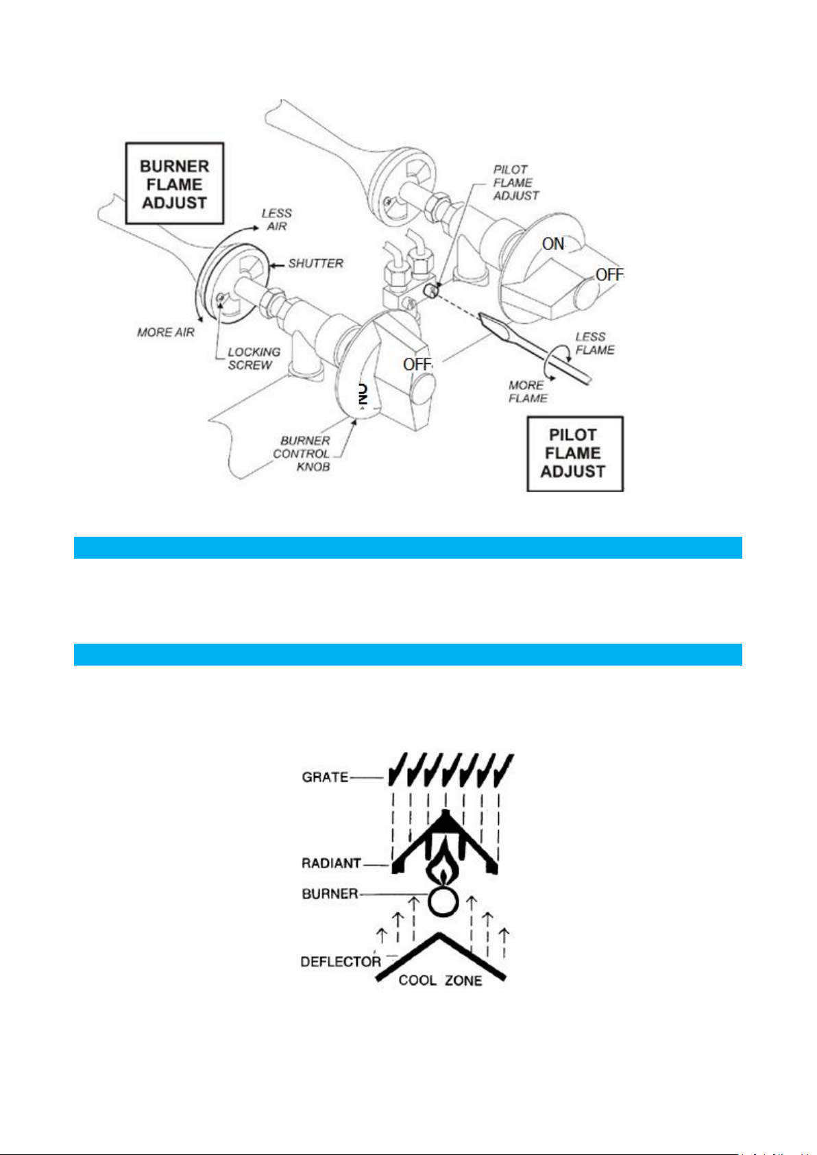
The charbroiler comes with several standard parts as illustrated. Each can be easily
removed and installed easily by hand for cleaning and maintenance. Note that the Burner
and Deflector are an assembly and are NOT designed to be disassembled. Regarding the
radiant cover, there are different materials for different models. ECB series come with cold
rolled steel material. The others come with cast iron material.
CLEANING
Scrape top grates during broiling with a wire brush to keep the grates clean. Do not allow
debris to accumulate on the grates.
Top grates may be immersed in strong commercial cleaning compound overnight. In the
morning, rinse with hot water to remove any residues of cleaning compound. Thoroughly dry
and apply cooking oil to prevent rusting.
Stainless steel surfaces may be cleaned using damp cloth with mild detergent and water
solution.
Places where fat, grease, or food can accumulate must be cleaned regularly
Never cover surface of unit with pans or other objects in attempt to “burn off ” or clean debris
from unit. This will cause a buildup of heat that can potentially damage and warp
components of the charbroiler.
MAINTENANCE:
• A qualified service company should check the unit for safe and efficient operation on an
annual basis.
• Gas piping shall be a certain size and installed to provide a supply of gas sufficient to meet
the full gas input of the equipment.
• A manual shut off valve should be installed upstream from the manifold within 4 ft. (1.2m)
of the equipment and in a position where it can be reached in the event of an emergency.
• Check entire gas piping system for leaks every so often. Using a gas leak detector or
soapy water solution is recommended.
• Install equipment under efficient exhaust hood with flameproof filters with a distance of no
less than 4 feet between the top of the equipment and the filters or any other combustible
materials.
*Shipped setup for Natural Gas and includes a kit for conversion to LPG.
LEVELING
It is important that the charbroiler is level front to back and left to right. Areas of uneven heat
distribution will occur on an unleveled unit. The charbroiler is equipped with adjustable legs.
Turn the feet at the bottom of the legs to adjust to level. The unit should be rechecked for
level anytime it has been moved.

USRESTAURANT® RESERVES THE RIGHT TO CHANGE SPECIFICATIONS WITHOUT NOTICE
7
VENTILATION HOOD
The broiler should be installed under a suitable ventilation hood. For safe operation and
proper ventilation, keep the space between the charbroiler and vent hood free from any
obstructions.
Trouble Shooting
PROBLEM
POSSIBLE CAUSES
Uneven heating, sides burning
A. Burner valves improperly adjusted
B. Fluctuating gas pressure
C. Improperly adjusted burner
Too much top heat
A. Burner valves adjusted too high
B. Faulty ventilation
C. Overrated gas pressure
D. Improperly adjusted burner
Uneven heat side to side
A. Burner valves improperly adjusted
B. Appliance is not level side to side
C. Improperly adjusted burner
Pilot outage
A. Pilot flame is set too low. Adjust pilot to
allow for gas flow.
B. Obstruction in pilot orifice
C. Low gas pressure.
Yellow burner flames
A. Open burner shutters until flames are
blue
Lifting burner flames
A. Close burner shutters until flames touch
burner
Fluctuating gas pressure
A. Check for clogged vent on regulator

USRESTAURANT® RESERVES THE RIGHT TO CHANGE SPECIFICATIONS WITHOUT NOTICE
8
Product Specification Sheet
MODEL
STYLE(Manual)
GAS TYPE
MANIFOLD
PRESSURE
Total B.T.U.
per Hour
CCB-24
2 Burners w/
individual control
Natural Gas
Propane Gas
4.0" W.C.
10.0" W.C.
60,000
CCB-36
3 Burners w/
individual control
Natural Gas
Propane Gas
4.0" W.C.
10.0" W.C.
90,000
CCB-48
4 Burners w/
individual control
Natural Gas
Propane Gas
4.0" W.C.
10.0" W.C.
120,000
CCB-60
5 Burners w/
individual control
Natural Gas
Propane Gas
4.0" W.C.
10.0" W.C.
150,000
This manual suits for next models
3
Table of contents
Popular Broiler manuals by other brands

Bakers Pride
Bakers Pride Dante CBBQ-30S Operation manual

MONTAGUE
MONTAGUE E36W36 Instructional manual

Maxi-matic
Maxi-matic Elite PLATINUM ETO-140C instruction manual

Sierra
Sierra SRRB-12 owner's manual

Blodgett
Blodgett B36-NFR Installation and operation manual

U.S. Range
U.S. Range U.S. Range UIR36C Installation and operation manual