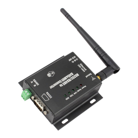
Usr USR-TCP232- E User manual

Multifunctional serial to Ethernet module user manual www.tcp232.net
Jinan USR IOT Technology Co., Ltd freda@usr.soPage 1 /
/
/
/9
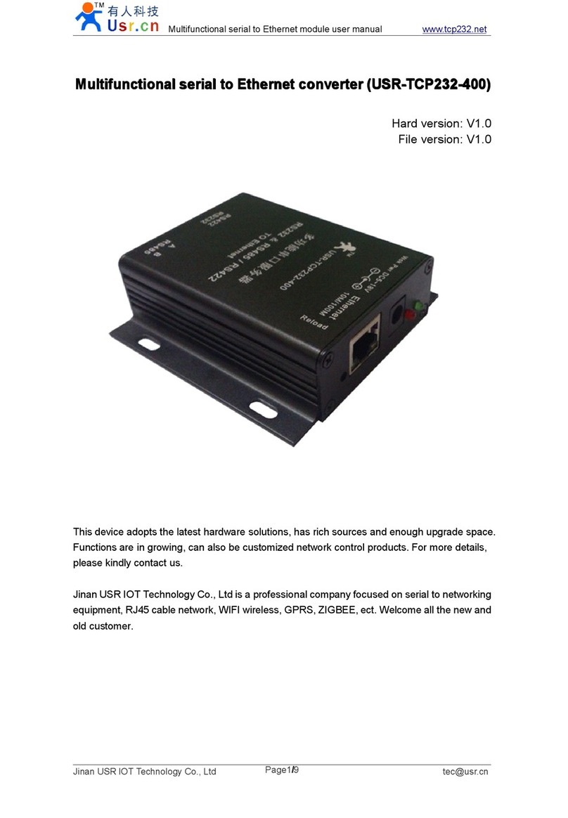
Multifunctional
Multifunctional
Multifunctional
Multifunctional S
S
S
S erial
erial
erial
erial to
to
to
to E
E
E
E thernet
thernet
thernet
thernet converter
converter
converter
converter
(USR-TCP232- E )
(USR-TCP232- 400 )
(USR-TCP232- 500 )
File version: V1. 1
Jinan USR IOT Technology Co., Ltd. works on LAN and WAN and wireless for MCU to
Ethernet Solutions, Ethernet, WIFI, GPRS, Zigbee and Wireless modules, we can supply
custom design for those usage, look ing forward to cooperat e with you.

Multifunctional serial to Ethernet module user manual www.tcp232.net
Jinan USR IOT Technology Co., Ltd freda@usr.soPage 2 /
/
/
/9
Contents
Contents
Contents
Contents
Multifunctional S erial to E thernet converter ......................................................................................... 1
1. Introduction ......................................................................................................................................... 4
1.1. Overview ................................................................................................................................. 4
1.2 Features ...................................................................................................................................... 4
1.2. Applications ............................................................................................................................. 5
1.3. Order information ................................................................................................................... 5
1.4. Electrical
c
haracteristics ......................................................................................................... 5
2. Work Mode .......................................................................................................................................... 6
2.1. Block diagram ......................................................................................................................... 6
2.2. UDP mode ............................................................................................................................... 6
2.3. TCP Client mode ..................................................................................................................... 7
2.4. UDP Server mode ................................................................................................................... 8
2.5. TCP Server mode .................................................................................................................... 9
2.6. Httpd Client mode ................................................................................................................. 10
2.7. TCP Auto mode ..................................................................................................................... 11
2.8. WEB to Serial mode ............................................................................................................. 12
3. Hardware interface: .......................................................................................................................... 14
3.1. USR-TCP232-E .................................................................................................................... 14
3.1.1. Hardware ..................................................................................................................... 14
3.1.2. Power .......................................................................................................................... 14
3.1.3. LED status .................................................................................................................. 14
3.1.4. Serial(TTL) interface ................................................................................................. 14
3.2. USR-TCP232-400 ................................................................................................................. 15
3.2.1. Hardware ..................................................................................................................... 15
3.2.2. Power .......................................................................................................................... 15
3.2.3. LED status .................................................................................................................. 16
3.2.4. RS232 interface .......................................................................................................... 16
3.2.5. RS485 /RS422 interface ........................................................................................ 16
3.3. USR-TCP232-500 ................................................................................................................. 17
3.3.1. Hardware ..................................................................................................................... 17
3.3.2. Power .......................................................................................................................... 17
3.3.3. LED status .................................................................................................................. 17
3.3.4. RS232 interface .......................................................................................................... 17
3.3.5. RS485 /RS422 interface ........................................................................................ 18
3.4. RJ45 interface ........................................................................................................................ 18
3.5. Reload .................................................................................................................................... 18
4. Paramters configuration ................................................................................................................... 19
4.1. Web page ............................................................................................................................... 19
4.2. Serial port .............................................................................................................................. 19

Multifunctional serial to Ethernet module user manual www.tcp232.net
Jinan USR IOT Technology Co., Ltd freda@usr.soPage 3 /
/
/
/9
4.3. network command(setup software) ...................................................................................... 20
5. Specific functions ............................................................................................................................. 21
5.1. Hardware flow control .......................................................................................................... 21
5.2. User MAC address ................................................................................................................ 21
5.3. Telnet Timeout ...................................................................................................................... 22
5.4. Send RST command through network ................................................................................. 23
5.5. Firmupdate ............................................................................................................................. 23
6. Module USES ................................................................................................................................... 25
6.1. Hardware connection ............................................................................................................ 25
6.2. Login ...................................................................................................................................... 26
6.3. Default working mode test ................................................................................................... 28
6.4. Common questions ............................................................................................................... 29
6.4.1. Work across network segment ................................................................................... 29
6.4.2. Ping is OK but can not open web pages ................................................................... 30
6.4.3. After firm update, can not open web page ................................................................ 30
6.4.4. When connection established, server received serval chars .................................... 30
6.4.5. Every serval seconds, module reconnect .................................................................. 30
7. C ontact us .......................................................................................................................................... 31
8. Modified history ............................................................................................................................... 32

Multifunctional serial to Ethernet module user manual www.tcp232.net
Jinan USR IOT Technology Co., Ltd freda@usr.soPage 4 /
/
/
/9
1.
1.
1.
1. Introduction
Introduction
Introduction
Introduction
1.1.
1.1.
1.1.
1.1. Overview
Overview
Overview
Overview
The USR-TCP232- E is an intelligent plug-and-play RS232 to Ethernet adapter that
enables any device or machine with a serial port, to become Ethernet network and
Internet enabled. Go from Ethernet to serial with the USR-TCP232- E . It features a
powerful built-in device server, so you can access your serial device from anywhere in the
world over internet! The USR-TCP232- E is easily configured via Ethernet, and can also
be set up through the serial port and web pages .
We Provide Network products and the best service to our customers.
• Chips • Modules • Software • Products
1.2
1.2
1.2
1.2 Features
Features
Features
Features
�New Cortex-M3 kernel, industrial working temperature range, elaborate optimization
LWIP protocol stack, stable and reliable.
�A RS232 port, can set COM port and working mode independently, work
independently, support RTS/CTS hardware flow control.
�A RS232/RS485 compatible port, auto adaptation.
�RS232 and RS485 can be used together, work independently, distinguish the
connected serial port via port number.
�Auto-MDI/MIDX function, discretionarily connect cross-over or direct network cable,
automatic switching.
�Support TCP Server, TCP Client, UDP, UDP Server, HTTPD Client various
of
work
modes.
�Support virtual serial work way, provide corresponding software.
�Serial port highest baud rate from 110bps to 230400 bps .
�wide voltage input, more applications.
�Support DHCP automatically access IP, can inquire the facility within network
through the UDP broadcast protocol.
�Supply the protocol for VIP customers, can integrate parameter seting function to
users ’ software applications.
�Provide PC TCP/IP SOCKET programming example, VB , C++ , Delphi , Android , IOS.
�The built-in web page, also parameter setting via web, can customize web pages for
users.
�Can also set via UDP, provide the set up protocol and software source code.
�Reload button, a key restore default Settings.
�RJ45 status indicator light, RJ45 interface built-in isolation transformer, 2 KV
isolation.

Multifunctional serial to Ethernet module user manual www.tcp232.net
/
/
/9
�The global only MAC address bought from IEEE, the user can define MAC address
(please state when you make order) .
�Support upgrade firmware via network.
�Support IP and domain name at the same time
�Support up to 4 link from client when act as TCP Server, send and receive data with
id.
�Can modify MAC address you wanted
�Can modify http server port for module built-in http server.
1.2.
1.2.
1.2.
1.2. Applications
Applications
Applications
Applications
�Fire and Security Panels
�
Vending Machines
�Point of Sale Terminals
�Remote equipment management
�
IT management services
�Access Control
�Industrial Control
�
Home Automation
�Instrumentation
�Building Control
�
Power Management
1.3.
1.3.
1.3.
1.3. Order
Order
Order
Order information
information
information
information
Type
Type
Type
Type Part
Part
Part
Part Numbers
Numbers
Numbers
Numbers Electric
Electric
Electric
Electric interface
interface
interface
interface
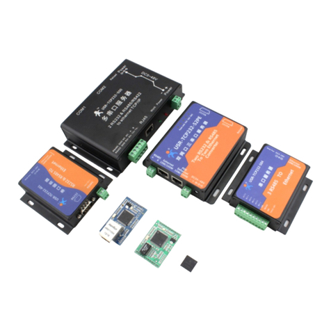
Serial to Ethernet Converter USR-TCP232- E 2 * TTL
Serial to Ethernet Converter USR-TCP232- 400 1 * RS232 , 1 * RS485 /RS422
Serial to Ethernet Converter USR-TCP232- 500 2 * RS232 , 1 * RS485 /RS422
Diagram 1 - 1 Order information
1.4.
1.4.
1.4.
1.4. Electrical
Electrical
Electrical
Electrical c
c
c
c haracteristics
haracteristics
haracteristics
haracteristics
DC Power Supply Voltage :
Two DC Voltage can be choose (for USR-TCP232-E, others see Hard interface )
VCC :type: 3.3V, min: 3.15 ,max: 3.45 V
VDD :type:
5V,
min: 4.5V ,max: 5.5V
Operating supply current : Max: 180 MA
Operating Temperature : 0~75 ° C (business version) - 25-80 ° C (industry version)
Storage temperature : -40~85 ° C

Multifunctional serial to Ethernet module user manual www.tcp232.net
/
/
/9
2.
2.
2.
2. Work
Work
Work
Work Mode
Mode
Mode
Mode
2.1.
2.1.
2.1.
2.1. Block
Block
Block
Block diagram
diagram
diagram
diagram
Take USR-TCP232-E for example ,show demo application of module USR-TCP232-E.
Serial to Ethernet
Converter
USR
-
TCP 232
- E
Ethernet
power
User
device
TTL
Diagram 2 - 1 USR-TCP232-E application demo
2.2.
2.2.
2.2.
2.2. UDP
UDP
UDP
UDP mode
mode
mode
mode
When in UDP mode, after power on, module listen on specific port.
MCU
51
51
51
51
,
,
,
,
AVR
AVR
AVR
AVR
,
,
,
,
PIC
PIC
PIC
PIC
,
,
,
,
ARM
ARM
ARM
ARM
RS
232
Ethernet
1 . PC listen a UDP port
2
.
Data transfer
With out connection
,
only data packet
1
.
Module listen a UDP port
Module work at UDP mode
Diagram 2 - 2 UDP mode
When received data from this udp port, send it to serial port;otherwise, when data is received
from serial port, send it to ethernet.

Multifunctional serial to Ethernet module user manual www.tcp232.net
/
/
/9
Diagram 2 - 3 UDP mode communication test
Note:
local port and remote port can be different.
2.3.
2.3.
2.3.
2.3. TCP
TCP
TCP
TCP Client
Client
Client
Client mode
mode
mode
mode
Open web pages and config module to
Telent Mode: TCP Client
Remote port number: 23
Telnet Server Addr: 192.168.0.131
Diagram 2 - 4 TCP Client mode
Use USR-TCP232-Test,

Multifunctional serial to Ethernet module user manual www.tcp232.net
/
/
/9
diagram 2 - 5 TCP Client communication test
2.4.
2.4.
2.4.
2.4. UDP
UDP
UDP
UDP Server
Server
Server
Server mode
mode
mode
mode
Like the socket UDP server in pc API. Many to one data transfer supported, the data
from uart/232/485 part will be transformed to the last UDP packet
’
s address.
Here show 2 UDP client communicate with server, server send data to the last client
communicates with it.

Multifunctional serial to Ethernet module user manual www.tcp232.net
/
/
/9
Diagram 7 Client 1 <-> server
Diagram 8 Client 2 <-> server
2.5.
2.5.
2.5.
2.5. TCP
TCP
TCP
TCP Server
Server
Server
Server mode
mode
mode
mode
TCP Server mode have 2 parameters: max link number and link type
1. max link number: 1 ~ 4;
2. Link type: typical, completely transparent, send data to all client;
extend1, communicate with id, otherwise abandon;
extend2, communicate with id, otherwise send to all client.
For link type extended 1 and extended 2:
When receive data from ethernet, module will send data to serial port with head
‘
I
’
‘
N
’
,followed by data.
’
I
’
represent incoming data,
‘
N
’
represent client index.
When user MCU want send data to module serial port, start with head
‘
O
’
‘
N
’
data...
‘
O
’
represent send out,
‘
N
’
represent which client.
When new TCP connection incoming, module will send
‘
C
’
‘
N
’
‘
M
’
to serial port, indicating
that there is current link
‘
N
’
accessed, total link number
‘
M
’
.
When link number have exceed maximum, new link requirment will lead to message
‘
F
’
‘
F
’
.
When disconnect, module will send
‘
D
’
‘
N
’
‘
M
’
, represent current link N is delete, left link
M.
Note:
serial data need to be sent in one package to module.

Multifunctional serial to Ethernet module user manual www.tcp232.net
/
/
/9
Diagram 2 - 8 web page configuration
2.6.
2.6.
2.6.
2.6. Httpd
Httpd
Httpd
Httpd Client
Client
Client
Client mode
mode
mode
mode
This function is easier used for web page developer.
We
establish one web server page, add
this:
[<?php echo $_GET['data']; ?>]
Means we can GET data from HTTP client
’
s request. Open this URL:
www.usr.cn/1.php?data=12345 , the web page is downbelow, we can see that the web server have
got the data(12345),
Diagram 2 - 9 Request www.usr.cn/1.php?
www.usr.cn/1.php?
www.usr.cn/1.php?
www.usr.cn/1.php? and upload data
Then we take another way, set USR-TCP232-E module Work mode HTTPD Client, Target
address www.usr.cn,
www.usr.cn,
www.usr.cn,
www.usr.cn, Target port 80,

Multifunctional serial to Ethernet module user manual www.tcp232.net
11
/
/
/
/9
Diagram 2 - 10 config HTTPD Client
Diagram 2 - 11 module act as HTTPD Client
Note.
HTTPD Client based on TCP Client.
2.7.
2.7.
2.7.
2.7. TCP
TCP
TCP
TCP Auto
Auto
Auto
Auto mode
mode
mode
mode
When power on, module work as TCP Server, listen on local port, but if there is data received
from serial port before any connection, module will try to connect remote IP and port as TCP
Client.

Multifunctional serial to Ethernet module user manual www.tcp232.net
/
/
/9
Diagram 2 - 12 TCP Auto act as Server
Diagram 2 - 13 TCP Auto act as Client
2.8.
2.8.
2.8.
2.8. WEB
WEB
WEB
WEB to
to
to
to Serial
Serial
Serial
Serial mode
mode
mode
mode
Communication mode between serial port and web pages.

Multifunctional serial to Ethernet module user manual www.tcp232.net
/
/
/9
Diagram 2 - 14 config module to WEB to Serial mode
Select Telnet mode Web to Serial ,
Diagram 2 - 15 WEB to Serial communication demo
Note:
1、received window show data only when click on
“
read ” button or select
“
Auto read ” button.
2、whether WEB to Serial mode or not, send web data to serial always work.

Multifunctional serial to Ethernet module user manual www.tcp232.net
/
/
/9
3.
3.
3.
3. Hardware
Hardware
Hardware
Hardware interface:
interface:
interface:
interface:
3.1.
3.1.
3.1.
3.1. USR-TCP232-E
USR-TCP232-E
USR-TCP232-E
USR-TCP232-E
3.1.1.
3.1.1.
3.1.1.
3.1.1. Hardware
Hardware
Hardware
Hardware
Diagram 3 - 1 USR-TCP232-E
1) Mechanical dimesion : ( L × W × H): 5 5 × 30 × 23 .2 (mm) including RJ45 and connector ;
2) PCB dimension (L × W): 50 .4 × 30.0 (mm) ;
3) 5V 3.3V double power input ,choose 1 input
1) 2 * serial(2 * TTL)
2) TTL serial port support hardware flow control
3.1.2.
3.1.2.
3.1.2.
3.1.2. Power
Power
Power
Power
Power supply socket, The input voltage range 3.3V or
5V
, current 150 MA. We default
supply high quality 5 V / 1 A power adapter.
3.1.3.
3.1.3.
3.1.3.
3.1.3. LED
LED
LED
LED status
status
status
status
Except for Link and Data of RJ45, there is one work LED interface
ID name
Description

Multifunctional serial to Ethernet module user manual www.tcp232.net
/
/
/9
1 Work
Just interface, have no LED on module,
If you needed, take this pin with LED and 510 ohm
resistor to GND.
See Pin8 for further explantion.
2 Link(green) On RJ45, when ethernet link established, on.
3 Data(yellow) On RJ45, wnen ethernet data communicate, twinkle.
Diagram 3 - 2 LED definition
3.1.4.
3.1.4.
3.1.4.
3.1.4. Serial(TTL)
Serial(TTL)
Serial(TTL)
Serial(TTL) interface
interface
interface
interface
The serial port is TTL level ( 2 * TTL serial port, can be directly connected to MCU ) .
number name Description
1 TXD0 Uart0 transmit data pin
2 RXD0 Uart0 receive data pin
3 CTS0 Uart0 RS232 clear to send
4 RTS0 Uart0 require to send
5 RXD1 Uart1 receive data pin
6 TXD1 Uart1 transmit data pin
Diagram 3 - 3 connector interface(include uart0 and uart1)
Note:
RS485 and RS422 are self adaption ports, according to RS485 connection that is RS485,
according to RS422 connection is RS422 .

Multifunctional serial to Ethernet module user manual www.tcp232.net
/
/
/9
3.2.
3.2.
3.2.
3.2. USR-TCP232-400
USR-TCP232-400
USR-TCP232-400
USR-TCP232-400
3.2.1.
3.2.1.
3.2.1.
3.2.1. Hardware
Hardware
Hardware
Hardware
Diagram 3 - 4 USR-TCP232-400
1) Mechanical dimesion : ( L × W × H): 90 × 84 × 2 5 (mm) including RJ45 and connector;
2) PCB dimension (L × W): 80.3 × 50. 3 (mm) ;
3) +5 ~ +12V power input;
4) DC power plug, 5.08 connector power input
5) 2 * serial(1 * RS232, 1 * RS485/422)
6) 1 * RS232 support hardware flow control
7) 1 * RS485/RS422
8) Specific: PIN 9 of the RS232 DB9 can connect to power for special uses.
3.2.2.
3.2.2.
3.2.2.
3.2.2. Power
Power
Power
Power
This system has three power supply interface,
a
power hub,
a
5.08 terminal, pin 9 of the two
serial com (through the PCB jumper short circuit, default closed).
Power supply socket, outer diameter 5.5 mm inner 2.1 mm standard size, inside plus, outside
minus. The input voltage range 5 ~ 48
V,
current 150 MA. We default supply high quality 5 V / 1
A power adapter.

Multifunctional serial to Ethernet module user manual www.tcp232.net
/
/
/9
Power supply socket, the terminal and pin 9 of the com , mutual unicom, can choose one
power supply in, and another power supply out, better adapt to the use environment.
3.2.3.
3.2.3.
3.2.3.
3.2.3. LED
LED
LED
LED status
status
status
status
Equipment have 4 indicator lights in total, sequence from left to right .
ID Name Description
1 Power(red) Bright after power on
2 Work(green) Flash at work
3 Link(green) In RJ45 port, bright after network connection
4 Data(yellow) In RJ45 port, flash
if
there are datas on network
Diagram 3 - 5 LED definition
3.2.4.
3.2.4.
3.2.4.
3.2.4. RS232
RS232
RS232
RS232 interface
interface
interface
interface
The serial port is male (needl), RS232 level (can be directly connected to computer serial),
part of RS232 pin sequences consistent to computer COM port. When connected with the
computer, we need to use cross cable (2-3 cross, 7-8 cross, 5-5 direct, 7-8 can don
’
t connect, but
musn
’
t direcly connect to computer . Otherwise, it might lead to irregularly work).
The DB9 interface contains the RS232, RS485 and RS422 interfaces.
Number RS232 RS485 RS422 Description
1 - B(-) TX- RS485 minus or RS422 transmit minus
2 RXD - - RS232 device receive data pin
3 TXD - - RS232 device transmit data pin
4 - - RX- RS422 receive minus
5 GND GND GND Signal ground
6 - A(+) TX+ RS485 plus or RS422 transmit plus
7 RTS - - RS232 require to send
8 CTS - - RS232 clear to send
9 - - RX+ RS422 receive plus
Diagram 3 - 6 DB9 interface
Note: this DB9 interface include RS232 and RS485/RS422.
3.2.5.
3.2.5.
3.2.5.
3.2.5. RS485
RS485
RS485
RS485 /RS422
/RS422
/RS422
/RS422 interface
interface
interface
interface
RS485 two wirings terminal, A
(DATA
+), B (DATA), when connected with RS485, A (+) to
A (+), B (-) to B (-).

Multifunctional serial to Ethernet module user manual www.tcp232.net
/
/
/9
RS422 interface also connected to RS232 nine needles binding post. The device have RS232
and RS485 interface, but can only use one in
a
time, autoadaptation, connect as RS485 is RS485
function, connect as RS422 wiring is RS422 function.
3.3.
3.3.
3.3.
3.3. USR-TCP232-500
USR-TCP232-500
USR-TCP232-500
USR-TCP232-500
3.3.1.
3.3.1.
3.3.1.
3.3.1. Hardware
Hardware
Hardware
Hardware
Diagram 3 - 7 USR-TCP232-500
3) Mechanical dimesion : ( L × W × H): 155 × 100 × 34 (mm) , including RJ45 and connector;
4) PCB dimension (L × W): 130.5 × 90.2 (mm) ;
5) +5 ~ +48V power input;
1) DC power plug, 5.08 connector power input
6) 3 * serial(2 * RS232, 1 * RS485/422)
7) 2 * RS232 support hardware flow control
8) 1 * RS485/RS422
9) Specific: PIN 9 of the RS232 DB9 can connect to power for special uses.
3.3.2.
3.3.2.
3.3.2.
3.3.2. Power
Power
Power
Power
This system has three power supply interface,
a
power hub,
a
5.08 terminal, pin 9 of the two
serial com (through the PCB jumper short circuit, default closed).

Multifunctional serial to Ethernet module user manual www.tcp232.net
/
/
/9
Power supply socket, outer diameter 5.5 mm inner 2.1 mm standard size, inside plus, outside
minus. The input voltage range 5 ~ 48
V,
current 150 MA. We default supply high quality 5 V / 1
A power adapter.
Power supply socket, the terminal and pin 9 of the com , mutual unicom, can choose one
power supply in, and another power supply out, better adapt to the use environment.
3.3.3.
3.3.3.
3.3.3.
3.3.3. LED
LED
LED
LED status
status
status
status
Equipment have 4 indicator lights in total, sequence from left to right .
ID Name Description
1 Power(red) Bright after power on
2 Work(green) Flash at work
3 Link(green) In RJ45 port, bright after network connection
4 Data(yellow) In RJ45 port, flash
if
there are datas on network
Diagram 3 - 8 LED definition
3.3.4.
3.3.4.
3.3.4.
3.3.4.
RS232
RS232
RS232
RS232 interface
interface
interface
interface
It have 2 * RS232 interface. The serial port is male (needl), RS232 level (can be directly
connected to computer serial), part of RS232 pin sequences consistent to computer COM port.
When connected with the computer, we need to use cross cable (2-3 cross, 7-8 cross, 5-5 direct,
7-8 can don
’
t connect, but musn
’
t direcly connect to computer. Otherwise, it might lead to
irregularly work).
The DB9 interface contains the RS232, RS485 and RS422 interfaces.
Number
name
Description
2RXD RS232 device receive data pin
3TXD RS232 device transmit data pin
5
GND Signal ground
7RTS RS232 require to send
8CTS RS232 clear to send
9 VCC Default not used. there is one pad jumper, default
disconnect, when connect, it can power supply outside
serial device.
Diagram 3 - 9 DB9 interface
Note: none

Multifunctional serial to Ethernet module user manual www.tcp232.net
/
/
/9
3.3.5.
3.3.5.
3.3.5.
3.3.5. RS485
RS485
RS485
RS485 /RS422
/RS422
/RS422
/RS422 interface
interface
interface
interface
RS485 two wirings terminal, A
(DATA
+), B (DATA), when connected with RS485, A (+) to
A (+), B (-) to B (-).
RS422 interface also connected to RS232 nine needles binding post. The device have RS232
and RS485 interface, but can only use one in
a
time, autoadaptation, connect as RS485 is RS485
function, connect as RS422 wiring is RS422 function.
3.4.
3.4.
3.4.
3.4. RJ45
RJ45
RJ45
RJ45 interface
interface
interface
interface
Internet access port connection, module network interface is 10 M / 100 M adaptive, support
AUTO MDI/MDIX, can discretionarily connect cross-over or direct network cable. That is to say,
you can use direct cable to connect with computer or test.
Pin Name Description
1 TX+ Transceiver Data+
2 TX- Transceiver Data-
3 RX+ Receive Data+
4 n/c Not connected
5 n/c Not connected
6 RX- Receive Data-
7 n/c Not connected
8 n/c Not connected
Diagram 3 - 10 RJ45 interface
3.5.
3.5.
3.5.
3.5. Reload
Reload
Reload
Reload
This button is used to restore factory settings. Press the button and power on, then free this
Reload button, device will be factory settings.
Default settings main parameters as follows
Address type :static IP
Static IP Address :192.168.0.7
User name :admin
password :admin
Module name :USR-TCP232-E
Using web pages can also restore default settings.
Diagram 3 - 11 restore defaults through web pages
Other manuals for USR-TCP232- E
1
This manual suits for next models
2
Table of contents
Other Usr Media Converter manuals
Popular Media Converter manuals by other brands

Kramer
Kramer VA-1VGA user manual

Manhattan
Manhattan 317405 user manual

Speaka Professional
Speaka Professional 2299210 operating instructions

Allied Telesis
Allied Telesis AT-G8LX10 specification

Diamond Multimedia
Diamond Multimedia VC500 Troubleshooting

IMC Networks
IMC Networks PSE-McBasic Series features and benefits