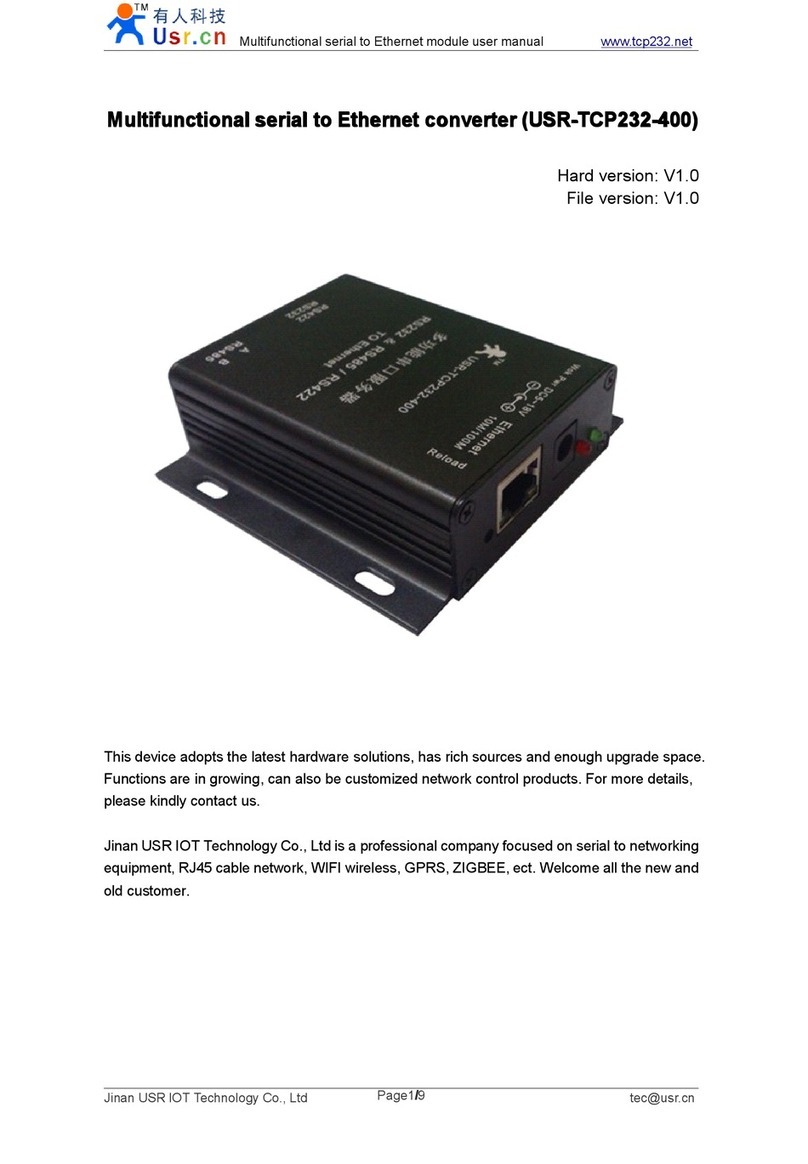
Usr USR-TCP232-T User manual

RS232 Serial
TTL UART
TO Ethernet TCPIP convert Module www.usr.cn
Jinan USR Technology Co., Ltd. Page 1 of 26 sales@usr.cn
RS232
RS232
RS232
RS232 Serial
Serial
Serial
Serial TO
TO
TO
TO Ethernet
Ethernet
Ethernet
Ethernet convert
convert
convert
convert Module
Module
Module
Module
USR-TCP232-T
Hard Version: V2.0
Doc Version: V1. 1
2011-08-16
Jinan USR Technology Co., Ltd. works on LAN and WAN and wireless for MCU to Ethernet Solutions, Ethernet,
WIFI, GPRS, Zigbee and Wireless modules, we can supply custom design for those usage, look forward to c ooperation
with you.
Key words: RS232
RS232
RS232
RS232 to
to
to
to Ethernet,
Ethernet,
Ethernet,
Ethernet, serial
serial
serial
serial to
to
to
to Ethernet,
Ethernet,
Ethernet,
Ethernet, Ethernet
Ethernet
Ethernet
Ethernet to
to
to
to serial
serial
serial
serial module,
module,
module,
module, RS232
RS232
RS232
RS232 serial
serial
serial
serial to
to
to
to TCP/IP
TCP/IP
TCP/IP
TCP/IP
Ethernet
Ethernet
Ethernet
Ethernet server
server
server
server ,
,
,
, TCPIP
TCPIP
TCPIP
TCPIP to
to
to
to RS232
RS232
RS232
RS232 convert
convert
convert
convert
Contact
Contact
Contact
Contact us:
us:
us:
us:
W
ebsite: http://www.usr.cn http://en.usr.cn
Address: Shengfu garden, D5-3-302, Jinan, Shandong, China
Email: sales@usr.cn tec@usr.cn
MSN: [email protected]om

RS232 Serial
TTL UART
TO Ethernet TCPIP convert Module www.usr.cn
Jinan USR Technology Co., Ltd. Page 2 of 26 sales@usr.cn
Phone: 86-531-55507297
Contents
Contents
Contents
Contents
RS232 Serial TO Ethernet convert Module .................................................................................................................. 1
1. Introduction .................................................................................................................................................... 3
1.1 Overview .............................................................................................................................................. 3
1.2 F eatures ................................................................................................................................................ 3
1 . 3 Applications .......................................................................................................................................... 3
1.4 Order information .................................................................................................................................. 4
1.5 Electrical Characteristics ....................................................................................................................... 4
2. Work Mode ..................................................................................................................................................... 5
2.1 Block diagram ....................................................................................................................................... 5
2.2 TCP Client Mode ................................................................................................................................... 5
2.3 UDP client mode ................................................................................................................................... 5
2.4 UDP server Mode .................................................................................................................................. 6
2.5 TCP server Mode ................................................................................................................................... 7
3. Hardware Description ..................................................................................................................................... 8
3.1 LED status ............................................................................................................................................ 8
3.2 Pin description ...................................................................................................................................... 8
3.3 Connection Diagram .............................................................................................................................. 8
3.4 Package ................................................................................................................................................. 9
4. Configure ..................................................................................................................................................... 10
4.1 configure command format .................................................................................................................. 10
4.2 configure through rs232 ....................................................................................................................... 11
4.3 configure through RJ45 ........................................................................................................................ 12
5. Test Methods ................................................................................................................................................ 13
5.1 General Test ........................................................................................................................................ 13
5.2 virtual COM ........................................................................................................................................ 17
6. Apps ............................................................................................................................................................. 21
6.1 COM<->TCP/UDP<->server ............................................................................................................... 21
6.2 Virtual COM ....................................................................................................................................... 21
6.3 COM <-> TCP/UDP <-> COM ............................................................................................................ 22
6.4 many COM <-> UDP server <-> COM ................................................................................................. 22
6.5 COM<-> TCP/UDP<->proxy server <->TCP/UDP<->COM ................................................................. 23
6.6 COM <-> TCP/UDP <-> server ............................................................................................................ 24
7. Background Knowledge ................................................................................................................................ 25
8. Contact us ..................................................................................................................................................... 26
9. Doc History .................................................................................................................................................. 26

RS232 Serial
TTL UART
TO Ethernet TCPIP convert Module www.usr.cn
Jinan USR Technology Co., Ltd. Page 3 of 26 sales@usr.cn
1.
1.
1.
1. Introduction
Introduction
Introduction
Introduction
1.1
1.1
1.1
1.1 Overview
Overview
Overview
Overview
The USR-TCP232-T is an intelligent plug-and-play RS232 to Ethernet adapter that enables any device or machine
with a serial port, to become Ethernet network and Internet enabled. Go from Ethernet to serial with the
USR-TCP232-T . It features a powerful built-in device server, so you can access your serial device from anywhere in
the world over internet! The USR-TCP232-T is easily configured via Ethernet, and can also be set up through the
serial port.
We
Provid e Network products and the best service to our customers.
•Chips •Modules •Software •Products
1.2
1.2
1.2
1.2 F
F
F
F eatures
eatures
eatures
eatures
�Auto detected 10/100M High speed Ethernet
�AUTO MDI/MDIX, Use crossover cable or parallel cable connection
�Baud rate 300 ~ 25600 bps
�TCP Server, TCP Client, UDP client , UDP server
�C an work as Virtual COM
�Auto reconnect TCP connection
�Socket program reference
�Free setup software and setup Agreement available
�Agreement: ETHERNET, ARP,
IP,
UDP, TCP
�3.3V and 5V two power input interface
�OEM and custom versions available
1
1
1
1 .
.
.
. 3
3
3
3 Applications
Applications
Applications
Applications
�Fire and Security Panels
�Vending Machines
�Point of Sale Terminals
�Remote equipment management
�IT management services
�Access Control
�Industrial Control
�Home Automation
�Instrumentation
�Building Control
�Power Management

RS232 Serial
TTL UART
TO Ethernet TCPIP convert Module www.usr.cn
Jinan USR Technology Co., Ltd. Page 4 of 26 sales@usr.cn
1.4
1.4
1.4
1.4 Order
Order
Order
Order information
information
information
information
Type
Type
Type
Type Part
Part
Part
Part Numbers
Numbers
Numbers
Numbers Electric
Electric
Electric
Electric interface
interface
interface
interface
Serial to Ethernet Adapter USR-TCP232-T TTL
Serial to Ethernet Adapter USR-TCP232-4 RS485
Serial to Ethernet Adapter USR-TCP232-2 RS232
Serial to Ethernet Adapter USR-TCP232-2 4 RS232/RS485 choose by jumper
Serial to Ethernet Adapter USR-TCP232-D
DIP module in TTL version,
without RJ45 on board.
Modbus, Ethernet/IP and Encrypted Versions are also available
1.5
1.5
1.5
1.5 Electrical
Electrical
Electrical
Electrical Characteristics
Characteristics
Characteristics
Characteristics
DC Power Supply Voltage :Two DC Voltage can be choose
VCC :type: 3.3V, min: 3.15 ,max: 3.45 V
VDD :type:
5V,
min: 4.5V ,max: 5.5V
Operating supply current :Max : 1 80 MA
Operating Temperature :0~75 ° C ( business version ) – 25-80 ° C (industry version)
Storage temperature :-40~85 ° C

RS232 Serial
TTL UART
TO Ethernet TCPIP convert Module www.usr.cn
Jinan USR Technology Co., Ltd. Page 5 of 26 sales@usr.cn
2.
2.
2.
2. Work
Work
Work
Work Mode
Mode
Mode
Mode
2.1
2.1
2.1
2.1 Block
Block
Block
Block diagram
diagram
diagram
diagram
USR
-
TCP
232
- T
RS
232
to Ethernet
1
2
3
6
MCU
51
51
51
51
,
,
,
,
AVR
AVR
AVR
AVR
,
,
,
,
PIC
PIC
PIC
PIC
,
,
,
,
ARM
ARM
ARM
ARM
VCCVCC
RXD
RXD
RXD
RXD
TXD
TXD
TXD
TXD
TXD
TXD
TXD
TXD
RXD
RXD
RXD
RXD
Tx
Tx
Tx
Tx
+
+
+
+
Tx
Tx
Tx
Tx
-
-
-
-
Rx
Rx
Rx
Rx
+
+
+
+
Rx
Rx
Rx
Rx
-
-
-
-
2.2
2.2
2.2
2.2 TCP
TCP
TCP
TCP Client
Client
Client
Client Mode
Mode
Mode
Mode
MCU
51
51
51
51
,
,
,
,
AVR
AVR
AVR
AVR
,
,
,
,
PIC
PIC
PIC
PIC
,
,
,
,
ARM
ARM
ARM
ARM
RS
232
Ethernet
1
.
Module try to connect to server
2
.
Data transfer through the connection
1 . Server listen a TCP port
Module work at TCP Client mode
2.3
2.3
2.3
2.3 UDP
UDP
UDP
UDP client
client
client
client mode
mode
mode
mode
MCU
51
51
51
51
,
,
,
,
AVR
AVR
AVR
AVR
,
,
,
,
PIC
PIC
PIC
PIC
,
,
,
,
ARM
ARM
ARM
ARM
RS
232
Ethernet
1 . PC listen a UDP port
2
.
Data transfer
With out connection
,
only data packet
1
.
Module listen a UDP port
Module work at UDP mode

RS232 Serial
TTL UART
TO Ethernet TCPIP convert Module www.usr.cn
Jinan USR Technology Co., Ltd. Page 6 of 26 sales@usr.cn
2.4
2.4
2.4
2.4 UDP
UDP
UDP
UDP server
server
server
server Mode
Mode
Mode
Mode
Like the socket UDP server in pc API. Many to one data transfer supported, the data from uart/232/485 part will
be transformed to the last UDP packet
’
s address.
PC
- A
MCU
51
51
51
51
,
,
,
,
AVR
AVR
AVR
AVR
,
,
,
,
PIC
PIC
PIC
PIC
,
,
,
,
ARM
ARM
ARM
ARM
RS
232
Ethernet
Module work at UDP Server mode
PC
- B
PC-B Send a data to module
Module change the
target IP to pc
Data transfer from Module to PC-B
1
2
3
1 . PC listen a UDP port
2
.
Data transfer from Module to PC - A
1
.
Module listen a UDP port

RS232 Serial
TTL UART
TO Ethernet TCPIP convert Module www.usr.cn
Jinan USR Technology Co., Ltd. Page 7 of 26 sales@usr.cn
2.5
2.5
2.5
2.5 TCP
TCP
TCP
TCP server
server
server
server Mode
Mode
Mode
Mode
PC
- A
MCU
51
51
51
51
,
,
,
,
AVR
AVR
AVR
AVR
,
,
,
,
PIC
PIC
PIC
PIC
,
,
,
,
ARM
ARM
ARM
ARM
RS
232
Ethernet
1
.
PC connect to the port
2
.
data transfer from MCU to PC
1
.
module listen TCP port
USR
-
TCP 232
-
T work at TCP Server mode
PC
- B
PC
- C
N
e
w
p
c
c
o
n
n
e
c
t
e
d
D
a
t
a
t
r
a
n
s
f
e
r
g
o
a
n
d
b
a
c
k
PC
- D
It can accept
4
links at
the same time .

RS232 Serial
TTL UART
TO Ethernet TCPIP convert Module www.usr.cn
Jinan USR Technology Co., Ltd. Page 8 of 26 sales@usr.cn
3.
3.
3.
3. Hardware
Hardware
Hardware
Hardware Description
Description
Description
Description
3.1
3.1
3.1
3.1 LED
LED
LED
LED status
status
status
status
There is two leds
in
RJ45 connector, one is green, and the other is yellow.
LED name description
green Link state Light when 100Mbps network linked
yellow Data transfer Blink when there is data
in
or out
3.2
3.2
3.2
3.2 Pin
Pin
Pin
Pin description
description
description
description
pin name description
VDD Power 1 4.5~5.5V
VCC Power 2 3.3V
GND GND Power and Communications Ground
RST Reset pin 200ms GND reset the module
TXD UART t ransmission pin 5v tolerance
RXD UART receive pin 5v tolerance
CFG Configure pin
Configure mode when this pin GND, normal mode
when VCC or idle
3.3
3.3
3.3
3.3 Connection
Connection
Connection
Connection Diagram
Diagram
Diagram
Diagram
USR
-
TCP
232
- T
RS
232
to Ethernet
1
2
3
6
MCU
51
51
51
51
,
,
,
,
AVR
AVR
AVR
AVR
,
,
,
,
PIC
PIC
PIC
PIC
,
,
,
,
ARM
ARM
ARM
ARM
VCCVCC
GND
GND
GND
GND
RXD
RXD
RXD
RXD
TXD
TXD
TXD
TXD
GND
GND
GND
GND
TXD
TXD
TXD
TXD
RXD
RXD
RXD
RXD
Tx
Tx
Tx
Tx
+
+
+
+
Tx
Tx
Tx
Tx
-
-
-
-
Rx
Rx
Rx
Rx
+
+
+
+
Rx
Rx
Rx
Rx
-
-
-
-

RS232 Serial
TTL UART
TO Ethernet TCPIP convert Module www.usr.cn
Jinan USR Technology Co., Ltd. Page 10 of 26 sales@usr.cn
4.
4.
4.
4. Configure
Configure
Configure
Configure
parameter s: work mode ,source
IP,
source port ,net mask ,gateway ,UART baud rate ,destination IP ,destination
port.
Configure command is 24byte length.
Pull down CFG pin change the module into configuration mode when use UART to config .
4.1
4.1
4.1
4.1 configure
configure
configure
configure command
command
command
command format
format
format
format
Configure mode UART interface: 9600bps ,n,8,1
part bytes description example hex
prefix 2 0x55 0xAA 0x55 0xAA 0x55 0xAA
destination IP 4 destination IP 192.168.0.201 0x C9 0x 00 0x A8 0x C0
destination port 2 Destination port 8234 0x 2A 0x 20
Host IP 4 The IP module hold 192.168.0.7 0x 07 0x 00 0x A8 0x C0
Host port 2 TCP/UDP source port 20108 0x 8C 0x 4E
Gateway 4 Gateway IP 192.168.0.201 0x C9 0x 00 0x A8 0x C0
Work mode 1
0x01: TCP Client
0x00: UDP
0x02: UDP Server
TCP mode 0x01
baud rate 3 UART baud rate 115200 0x 00 0x C2 0x 01
Reserved 1 Reserved 00 0x00
checksum 1
Sum( destination
IP,
destination port, host
IP,
host port, gateway, work
mode, baud rate , reserved)
0xB9 0xB9
Full example :00 A8 C0 2A 20 07 00 A8 C0 8C 4E C9 00 A8 C0 01 00 C2 01 00 B9
* once in configure mode, the UART parameter change to 9600bps,n,8,1, and a ‘ U
’
ascii character is send out to
ensure the control MCU that
in
the configure mode. If the 24byte command has effect ,a ‘ K
’
ascii character is send
back to control MCU. If configure command format error, an ‘ E
’
character will be send back to control MCU. If the
error is the checksum not match , the 1byte right checksum will be send back to control MCU also .

RS232 Serial
TTL UART
TO Ethernet TCPIP convert Module www.usr.cn
Jinan USR Technology Co., Ltd. Page 11 of 26 sales@usr.cn
4.2
4.2
4.2
4.2 configure
configure
configure
configure through
through
through
through rs232
rs232
rs232
rs232
1. Power on module, and connect CFG to GND, make m odule to setup status.
2. Write settings and click Setup.
3. After Setting, left CFG free or connect to VCC, module begin work.
4 . T he save and Default button would useful for you.
Note:
Note:
Note:
Note: the
the
the
the module
module
module
module RS232
RS232
RS232
RS232 is
is
is
is TTL
TTL
TTL
TTL lever,
lever,
lever,
lever, you
you
you
you need
need
need
need a
a
a
a RS232
RS232
RS232
RS232 to
to
to
to TTL
TTL
TTL
TTL convert
convert
convert
convert to
to
to
to connect
connect
connect
connect it
it
it
it to
to
to
to you
you
you
you PC.
PC.
PC.
PC.

RS232 Serial
TTL UART
TO Ethernet TCPIP convert Module www.usr.cn
Jinan USR Technology Co., Ltd. Page 12 of 26 sales@usr.cn
4.3
4.3
4.3
4.3 configure
configure
configure
configure through
through
through
through RJ45
RJ45
RJ45
RJ45
Since 2011-08-02, the new version modules support Setup via RJ45.
Click search, find modules, choose the module, fill configration at left frame and then click Setup via RJ45.

RS232 Serial
TTL UART
TO Ethernet TCPIP convert Module www.usr.cn
Jinan USR Technology Co., Ltd. Page 13 of 26 sales@usr.cn
5.
5.
5.
5. Test
Test
Test
Test Methods
Methods
Methods
Methods
5.1
5.1
5.1
5.1 General
General
General
General
Test
Test
Test
Test
Default setup is as below picture.
T
est:
1. material : pc with rs232( or use USB to rs232 cable) ,3.3V or 5V power ,rs232 cable ,Network Cable , COM
debug software, TCPIP debug software(in CD, also can be download).
2. Connection : connect module rs232 to pc rs232, RJ45 to pc RJ45 or the same router ( same subnet). Notice
Notice
Notice
Notice :
:
:
:
USE
USE
USE
USE TTL
TTL
TTL
TTL to
to
to
to USB
USB
USB
USB convert
convert
convert
convert or
or
or
or TTL
TTL
TTL
TTL to
to
to
to RS232
RS232
RS232
RS232 convert
convert
convert
convert
3. Power on the module 3.3V on VCC or 5V on VDD.
3. Setup PC IP to 192.168.0.201.
4. PING 192.168.0.7 (it is optional action)

RS232 Serial
TTL UART
TO Ethernet TCPIP convert Module www.usr.cn
Jinan USR Technology Co., Ltd. Page 15 of 26 sales@usr.cn
C lick Listening, Open COM port .
The module will connect to the server and show the module IP and port.
5 . Now you can transfer data from PC RS232 to Ethernet.
You can use other TCP UDP test software and COM port test software as you like.

RS232 Serial
TTL UART
TO Ethernet TCPIP convert Module www.usr.cn
Jinan USR Technology Co., Ltd. Page 18 of 26 sales@usr.cn
4 . Setup as the follow pictures, you need to notice COM port, bond rate and work mode of PC, then click
Activate
Activate
Activate
Activate .
5 . After Activate click, a Virtual COM port COM2 , will be created, COM2 will receive data from TCP IP socket,
and send data to COM2 will convert to TCPIP socket data to remote Equipment .
If create failed, please notice to see error notice and log, when use Virtual COM Port, you should close other
software who use the same TCPIP port.
The success picture as follow:

RS232 Serial
TTL UART
TO Ethernet TCPIP convert Module www.usr.cn
Jinan USR Technology Co., Ltd. Page 19 of 26 sales@usr.cn
At this point, you can use your equipment as an ordinary serial port, and operate of local virtual serial port will
converted to operation of the remote module RS 232. The figure is show send data between the two serial port .
Table of contents
Other Usr Media Converter manuals