7. BYPASS/VU SWITCH - This 4-position switch allows you to bypass the active circuitry and control the meter
functionality.
8. INPUT GAIN CONTROL - These rotary switches control the amount of input gain. The scale (0 - 20) is showing how
much the signal is being padded before the active circuitry. The setting of 20 represents -20 dB of padding. Using
the gain trim pots, unity gain can be calibrated for a setting anywhere from -15 to -9. (See “Calibrating the Audio Lev-
els” under the “CALIBRATING PROCEDURES” section on pg. 9/10 for more details).
9. THRESHOLD - The threshold knob controls the sensitivity of the gain reduction circuit. When turned all the way
counter-clockwise, the UnFairchild will not compress at all. As the threshold control is turned clockwise, the amount
of compression will increase.
10. CHANNEL MODE - This rotary switch controls how the two channels interact.
11. TIME CONSTANT - The TIME CONSTANT rotary switch provides the original six (1-6) Fairchild presets, and provides
four more settings (VAR1 - VAR4) for added exibility. With settings 1 - 6, the attack and release times are preset. VAR1
- VAR4 allow you to access the variable attack and release controls, located on the lower panel. (See page 14 for more
information on the variable attack /release controls.)
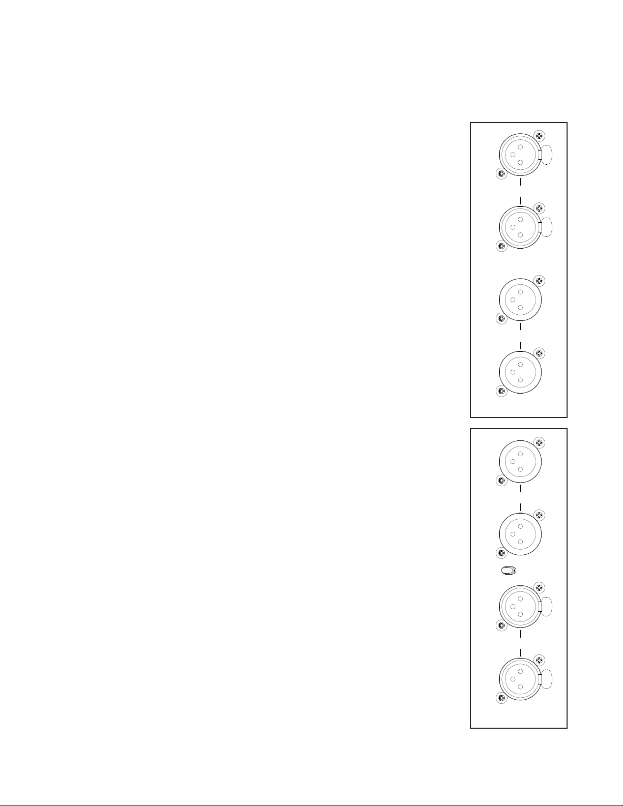
12. SIDE CHAIN INSERT - These toggle switches engage the SIDE CHAIN insert. When in the DOWN position, the Un-
Fairchild gain reduction circuit will respond to the signal connected to the input L/R jacks. When the switch is in the
UP position, the UnFairchild gain reduction circuit will respond to the signal connected to the SC RCV L/R jacks.
14. DC THRESHOLD - This control does 2 things: It adjusts the range of volume that the THRESHOLD control is sen-
sitive to and it changes the ratio or ‘knee’of the compression. In the fully counter-clockwise position the UnFairchild
will be sensitive to the lowest range of input levels and have the‘softest knee’or‘lowest possible ratio’. As the control
is turned clockwise, the ratio increases and the threshold becomes less sensitive and requires a higher setting to
maintain the same amount of compression.
•BYP:WhensettothebypassedBYPmode,thesignalpluggedtotheinputjackswillbeconnected
directly to the output jacks; bypassing all of the active electronics.
•VU:WhensettotheVUmode,theinputsignalwillbeprocessedbythecompressioncircuitandthe
VU will show the resulting output level.
•GR:WhensettotheGRmode,theVUmeterswillshowtheamountofgainreduction.
•BAL:WhensettotheBalancingBALmode,theunitisputintoaspecialmodeusedforbalancingthe
circuitry for optimal performance with the particular set of 6386 tubes that are installed. (See “balanc-
ing” under the “CALIBRATING PROCEDURES” section on pg. 9 for more details.)
•IND:Whensetto“IND”mode,thetwochannelswillbehaveliketwoindividualmonocompressors.
•LINK:WhensettotheLINKmode,thetwochannelswillbelinkedtogethertomakesurebothchan-
nels compress the same when compressing a stereo signal.
•M-S:WhensettotheM-Smode,theUnFairchildwillcompressallofthemonoinformationwithchan-
nel A, and all of the stereo information with channel B. In this mode, the mono and stereo information
will be compressed dierently and consequently the stereo image may uctuate when dierences
occour.
•M-SLINK:WhensettoM-SLINKmode,themonoandstereocompressionarelinkedtogethersothe
stereo image will not uctuate. You can now use the INPUT GAIN controls to change the balance be-
tween the mono and stereo signals. This can be used widen or narrow the stereo image.
8