UTAS RSE500A User manual

RF to Serial Extender
RSE500A
© 2010 UTAS Inc.
UTAS IS NOT RESPONSIBLE FOR TECHNICAL OR EDITING ERRORS IN THE CONTENTS OF THIS GUIDE. UTAS IS NOT
RESPONSIBLE FOR ANY SPECIAL, INDIRECT OR CONSEQUENTIAL DAMAGES OR ANY DAMAGES WHATSOEVER
RESULTING FROM ARISING OUT OF OR IN CONNECTION WITH THE USE OR PERFORMANCE OF DOCUMENTS, OR
LOSS OF USE.
THE CONTENTS AND INFORMATION INCLUDED IN THIS GUIDE ARE COPYRIGHT PROTECTED.
THUS, THEY CANNOT BE COPIED, REPRODUCED, OR TRANSLATED WITHOUT UTAS INC’S WRITTEN CONSENT.
UTAS
www.utas.co.kr
User Manual

Data Sheet of RF to Serial Extender –RSE500A
■RSE500A
■Terminal Block
■12V DC Adaptor
www.utas.co.kr
1
■Outline
RF to Serial Extender –RSE500A is an RF Controller which generates wirelessly received
control signals through RS232 and RS485 codes from Touch Panel via wireless 2.4GHz
RF band, and then transmits signals to the target devices through the cables.
■Features
·Various control method –RS232, RS485
· Addressable channels and IDs for multi-zone
· 2.4GHz RF(Zigbee Module )
·2.4GHz external antenna ( 2dB )
■Specification
·Terminal Block Type Port : Addressable 4 RS232 Ports, 1 RS485 Port
·Radio Frequency 2.4GHz (Built-in Zigbee Module)
·Coverage: approximately 100m ( in case 2dB antenna)
·Addressable 16 Extender IDs, Addressable 16 Channels
·Power –12V/1.5A SMPS DC Adaptor
·Color –Black
■Accessories
·RS232 Terminal Block X 4
·RS485 Terminal Block X 1
·DC Adaptor

Product Kit Details 2
■Top View
■Bottom View
■Rear View
Power LED Control LED RF Receiver antenna
(Basically 2dB)
Channel Switch ID Switch
RS485 portRS232 port DC Adapter power connection
(12V/1.5A)
www.utas.co.kr

www.utas.co.kr
Serial Devices Installation 3
■System Configuration
■Serial Device
Lighting
Switch
Matrix Switcher
RS232
Total Power
Projector Lighting
Decoder
Off switch
RS485
①Serial communication is the way to send the instruction composed of bit in regular sequence
along the one line of communication . For example, there are RS232 and RS485.
②RS232 is the way of communication of One-on-One, composed of TX, RX, Ground.
The distance of communication by cable is no more than 15m.
RS485 supports One-on-Multi communication, composed of 485 (+) and 485 (-).
The distance of communication by cable is more than 1Km.
③There are many serial communication devices such as Matrix Switcher, Projector, Lighting
control switch and other special devices to perform accurate works.
④The RS232 and RS485 protocol command value of each device consists of Hex or Ascii code.
When inputting protocol command value in UTAS Touch Panel, you have to use Hex code.
The protocol consists of Ascii code needs to convert to Hex code.
⑤For each device’s protocol command value, you can check in the manual of device or may
ask to the manufacturer of product.

RSE500A –Port Connection
www.utas.co.kr
4
■RS232 Port
■RS 485 Port
①The 5th port of RSE500A is exclusive port of RS485.
②It is used in direct connection with a device to support RS485.
■Channel, ID rotary switch
CH and ID located at the bottom is for adjusting RF frequency to communicate with touch
panel. They are to be installed to avoid being overlapped with other RF receivers .
①RSE500A is supported with 4 ports No.1 to 4 .
②You can connect to RS232 port using Terminal block.
③Each port sends the signal individually so that you can control each device independently.
■DC Power Port
Connect power connection with DC12V adaptor.
Note. Required to stay connected with power at any time.
RS232
Terminal block
RS485
Terminal block
Channel, ID
Rotary Switch
UTP cable for
communication RS232port
DC 12V Adapter
Power Supply
※If you use name tie for distinction, you can save time and effort to work
at the UI operation or device replacement later.

www.utas.co.kr
5
■RS232 Cable Installation
①RS232 is composed of TX, RX and Ground. (TX: send, RX : receive)
You need to connect TX of RSE500A to RX of device, otherwise it won’t work properly.
To put it the other way, you need to connect device’s TX to RX of RSE500A.
Ground
RX
TX
Ground
RX
TX
①RSE500A uses terminal block for easy connection of communication cable.
②UTP cable can be used for RS232 communication.
There are 8 lines in UTP cable. You can use two line of the same color as a set .
③Peel off the sheath of the UTP cable by 5mm and then connect to the terminal block.
5mm
Fasten the cable
screwing clockwise
using a flat-head screwdriver
☜
■RSE500A Terminal block
■D-sub 9 pin connector for RS232 (Sold separately)
①RS232 port of each device is different in manufacturers and models.
D-sub 9 pin connector is most frequently used for RS232 port.
Male type - Front Male type - Rear
1 5 5 1 Pin no. 1 to 9 is marked
in order.
☜
RS232 Cable Installation
Note. Check the spec. of target device for TX, RX, Ground in its manual .

RS232 Cable Installation
www.utas.co.kr
6
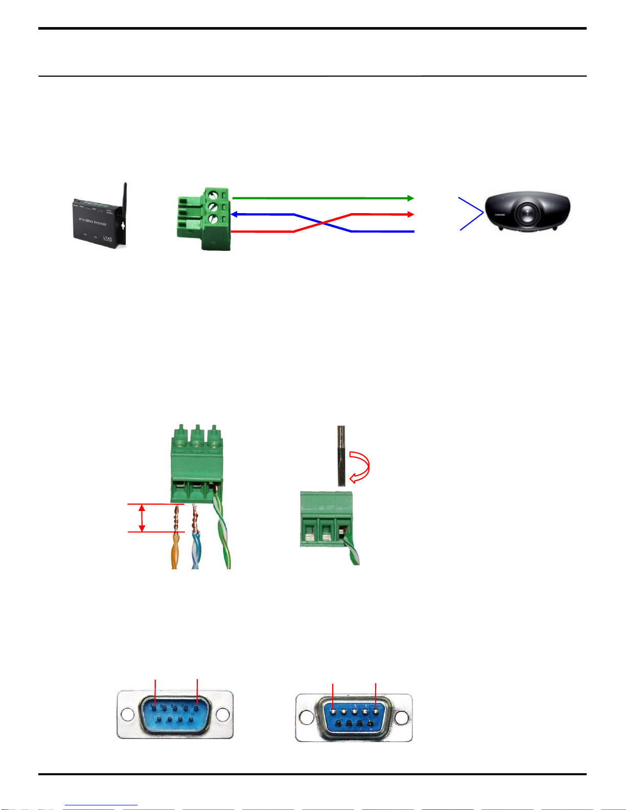
■Connection of Terminal block and D-sub 9 pin
Ground 5
TX 3
RX 2
Ground
RX
TX
③Make sure not to be cut down by soldering connector and UTP cable.
④Make sure to protect connector connected to UTP cable by using assembled D-sub case
(sold separately) from leftover of soldering.
⑤Need to install UTP cable within 15M because of the limitation of RS232 communication.
Note. You can check the value by receiving the data from TX of device only in touch panel
supported two-way communications. If the touch panel ((UX3500, ITRC8500DX etc.)
supported only one-way communication, then no need to connect to TX of device.
①Pin number of TX, RX, Ground used to communicate is differentin each manufacturer and
models even D-sub 9 pin port in the device being supported.
Check the pin number according to device’s manual, then connect it properly.
②Connect RX of device to terminal block TX of RSE500A.
Connect TX of device to terminal block RX of RSE500A.
Connect Ground of device to terminal block Ground of RSE500A.
■Other connector
You can control your device by connecting RX and Ground to RSE500A correctly even
RS232 port of your device is not supported by D-sub 9 pin.
Note. Purchase the proper connector to your device separately.

www.utas.co.kr
7
■RS485 Supported Device
①RS485 communication can control devices up to 1Km by using UTP cable.
(RS232 communication needs to within 15m only for cabling work.)
②RS485 communication supports One-on-Multi parallel connection so that you can connect
and control many device by using RS485 port of RSE500A.
③For example, lighting switch is one of the control device using RS485 .
UTAS’s lighting switch is equipped 8 IDs, and they are divided 1 to 8.
Because the divided ID can send protocol command separately, you can control up to 8
switches at once by 1 RS485 port of RSE500A.
RS485 Cable Installation
ID: 1 ID: 2 ID: 3 ID: 4 ID: 5 ID: 6 ID: 7 ID: 8
①RS485 consists of 485 (+), 485 (–).
It is to connect the same electrode of RSE500A and RS485 of device.
②The 5th port of RSE500A is exclusive port of RS485.
Connect to each device by using provided terminal block of RS485.
③Connect 485 (+) of RSE500A and 485 (+) of each device, 485 (–) of RSE500A and 485 (–)
of each device.
④Use UTP cable for RS485 communication like RS232 communication.
485 -
485 +
485 -
485 +
■RS485 Cable Installation
Note. Ask in advance if you want to divide IDs of lighting switch.

Installation Example
www.utas.co.kr
8
■Projector
■Matrix Switcher
■Lighting & Curtain
Table of contents
Popular Extender manuals by other brands

Ourten
Ourten OT-PLC302C-RS4 manual

GoMax Electronics
GoMax Electronics CV-57C user manual

J-Tech Digital
J-Tech Digital JTD-2865 user manual

Guntermann & Drunck
Guntermann & Drunck DL-DVI-Vision-Fiber series Installation and operating guide

AMG
AMG Active AMG1212 instruction manual

EtherWAN
EtherWAN ED3638 quick start guide