UTC Fire and Security interlogix TruVision TVD-DOME6-HR User manual

TruVision TVD-DOME6-HR
Camera
EN Pocket Guide
DE Kurzanleitung
ES Guía de bolsillo
FR Guide de poche
IT Guida rapida
NL Beknopte handleiding
PL Kieszonkowy przewodnik
PT Guia Rápido
RU Карманное руководство
TR Cep Kılavuzu
P/N 1076546B • ISS 05JUN12


1
Contents / Inhalt /
Contenido / Table des matières /
Indice / Inhoudsopgave / Spis treści
/ Índice / Содержание / İçindekiler
Figures ....................................................... 3
EN ............................................................. 10
DE ............................................................. 13
ES .............................................................. 16
FR .............................................................. 19
IT ............................................................... 22
NL .............................................................. 25
PL .............................................................. 28
PT .............................................................. 31
RU ............................................................. 34
TR .............................................................. 37

2
Legal / Rechtliche Angaben / Información
legal / Informations légales / Note legali /
Juridisch / Informacje prawne /
Informação legal / Нормативно-
правовые аспекты / Yasal......................40

3
Figures
EN Figure 1: Cables
A. Video cable; B. Power cable
DE Abbildung 1: Kabel
A. Videokabel; B. Stromkabel
ES Figura 1: Cables
A. Cable de vídeo; B. Cable de
alimentación

4
FR Figure 1 : Câbles
A. Câble vidéo ; B. Câble dʼalimentation
IT Figura 1: Cavi
A. Cavo video; B. Cavo di alimentazione
NL Afbeelding 1: Kabels
A. Videokabel; B. Voedingskabel
PL Rysunek 1: Kable
A. Przewód wideo; B. Kabel zasilania
PT Figura 1: Cabos
A. Cabo de vídeo; B. Cabo de
alimentação
RU Рис. 1. Кабели
A. Видеокабель; B. Кабель питания
TR Şekil 1: Kablolar
A. Video kablosu; B. Güç kablosu

5
EN Figure 2: Dome dimensions (mm)
DE Abbildung 2: Dome-Abmessungen (mm)
ES Figura 2: Dimensiones del domo (mm)
FR Figure 2 : Dimensions du dôme (mm)
IT Figura 2: dimensioni della dome (mm)
NL Afbeelding 2: Afmetingen dome (mm)
PL Rysunek 2: wymiary kopuły (mm)
PT Figura 2: Dimensões da dome (mm)
RU Рис. 2. Габариты купола (мм)
TR Şekil 2: Dome boyutları(mm)

6
TVD-DOME6-HR TVD-DOME5-HR-9
EN Figure 3: Camera adjustments
A. Platform vertical adjustment; B. Rotor
horizontal adjustment
DE Abbildung 3: Kameraeinstellungen
A. Vertikale Ausrichtung der Plattform;
B. Horizontale Ausrichtung des Rotors
ES Figura 3: Ajustes de la cámara
A. Ajuste vertical de la plataforma;
B. Ajuste horizontal del rotor
FR Figure 3 : Réglages caméra
A. Réglage vertical de la plate-forme ;
B. Réglage horizontal du rotor

7
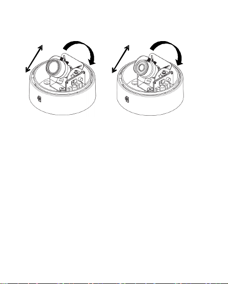
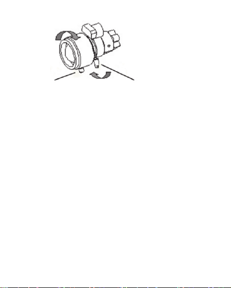
IT Figura 3: regolazioni della telecamera
A. Regolazione verticale della piattaforma;
B. Regolazione orizzontale del rotore
NL Afbeelding 3: Camera afstellen
A. Platform verticaal afstellen;
B. Rotor horizontaal afstellen
PL Rysunek 3: regulacja kamery
A. Regulacja pionowa modułu;
B. Regulacja pozioma podstawy
PT Figura 3: Ajustes da câmara
A. Ajuste vertical da plataforma;
B. Ajuste horizontal do rotor
RU Рис. 3. Регулировка камеры
A. Регулировка вертикального
положения платформы; B. Регулировка
горизонтального положения
вращающейся части
TR Şekil 3: Kamera ayarları
A. Platformun dikey ayarları; B. Rotorun
yatay ayarları

8
AB
EN Figure 4: Focus and zoom adjustments
A. Zoom ring thumbscrew; B. Ring
thumbscrew
DE Abbildung 4: Fokus- und
Zoomeinstellung
A. Zoom-Ringschraube; B. Fokus-
Ringschraube
ES Figura 4: Ajustes de enfoque y zoom
A. Tornillo de palometa del anillo del zoom;
B. Tornillo de palometa del anillo del
enfoque
FR Figure 4 : Réglages de la mise au point
et du zoom
A. Vis à serrage à main de la bague
de zoom ; B. Vis à serrage à main de
la bague

9
IT Figura 4: regolazioni dello zoom e della
messa a fuoco
A. Vite a testa zigrinata della ghiera dello
zoom; B. Vite a testa zigrinata della ghiera
NL Afbeelding 4: Zoomen en scherpstellen
A. Duimschroef zoomring; B. Duimschroef
focusring
PL Rysunek 4: regulacja powiększenia
i ostrości
A. Śruba blokująca pierścieńregulacji
powiększenia; B. Śruba blokująca pierścień
PT Figura 4: Ajustes de focagem e de zoom
A. Parafuso de orelhas do anel de zoom;
B. Parafuso de orelhas do anel
RU Рис. 4. Настройка масштаба ифокуса
A. Винт кольца масштабирования;
B. Винт кольца фокусировки
TR Şekil 4: Fokus ve zoom ayarları
A. Zoom halkasıkelebek vidası; B. Halka
kelebek vidası

EN 10
EN
Overview
This is the TruVision TVD-DOME6-HR and TVD-
DOME5-HR-9 Camera Pocket Guide. This pocket
guide describes a standard installation.
Installation
To install the camera:
1. Fasten the camera to a wall or ceiling
(or another solid surface). The camera must be
stable when connected.
2. Connect the 75 Ωcoaxial cable to the video
output.
3. Connect the power cable to the camera.
4. Adjust the camera position and angle as
required.
Angle adjustment
To adjust the vertical angle of the platform up to
180 degrees, turn the platform (Figure 3A on
page 6).

11 EN
To adjust the horizontal angle of the rotor up to 350
degrees, turn the rotor on the platform (Figure 3B
on page 6).
Focus and zoom
To adjust the camera zoom and focus, see Figure 4
on page 8 and do the following:
1. Loosen the zoom ring thumbscrew (Figure 4A).
2. Turn the zoom ring to set the desired zoom.
3. Tighten the zoom ring thumbscrew.
4. Loosen the focus ring thumbscrew (Figure 4B).
5. Turn the focus ring to set the desired focus.
6. Tighten the focus ring thumbscrew.
Maintenance
To clean inside and outside the camera, do not use
any organic or corrosive cleaning solutions. When
cleaning the camera, turn off the power, and use a
clean cloth with some water.

EN 12
Specifications
Power supply 24 VAC (230 mA) /
12 VDC (210 mA)
Power
consumption
2.45 W
2.52 W
Weight 0.49 lb. (225 g)
Dimensions
(H × Ø)
3.26 x 4.18 in.
(83 x 106 mm)
Operating
temperature
14 to 122°F
(-10 to +50°C)

13 DE
DE
Übersicht
Dies ist die Kurzanleitung für die Kameras TruVision
TVD-DOME6-HR und TVD-DOME5-HR-9. In dieser
Kurzanleitung wird die Standardinstallation
beschrieben.
Installation
Die Kamera montieren:
1. Befestigen Sie die Kamera an einer Wand oder an
der Decke (oder an einer anderen stabilen
Fläche). Die Kamera muss fest angebracht
werden, bevor sie angeschlossen wird.
2. Schließen Sie an den Videoausgang ein
Koaxialkabel (75 Ω) an.
3. Schließen Sie das Stromkabel an die Kamera an.
4. Passen Sie Position und Winkel der Kamera nach
Bedarf an.

DE 14
Winkeleinstellung
Den vertikalen Winkel der Plattform können Sie auf bis
zu 180 Grad einstellen, indem Sie die Plattform drehen
(Abbildung 3A auf Seite 6).
Den horizontalen Winkel des Rotors können Sie auf
bis zu 350 Grad einstellen, indem Sie den Rotor auf
der Plattform drehen (Abbildung 3B auf Seite 6).
Fokus- und Zoom
Beachten Sie zur Einstellung von Zoom und Fokus
Abbildung 4 auf Seite 8und gehen Sie wie folgt vor:
1. Lösen Sie die Schraube am Zoom-Ring
(Abbildung 4A).
2. Drehen Sie den Zoom-Ring, bis der gewünschte
Zoom eingestellt ist.
3. Ziehen Sie die Schraube am Zoom-Ring fest.
4. Lösen Sie die Schraube am Fokusring (Abbildung
4B).
5. Drehen Sie den Fokusring, bis die gewünschte
Bildschärfe eingestellt ist.
6. Ziehen Sie die Schraube am Fokusring fest.

15 DE
Wartung
Verwenden Sie zur Innen- und Außenreinigung der
Kamera weder organische noch ätzende
Reinigungsmittel. Schalten Sie die Kamera aus, bevor
Sie sie reinigen und verwenden Sie zur Reinigung ein
feuchtes, sauberes Tuch.
Technische Daten
Netzteil 24 VAC (230 mA) /
12 VDC (210 mA)
Leistungsaufnahme 2,45 W
2,52 W
Gewicht 225 g
Abmessungen (H × Ø) 83 x 106 mm
Betriebstemperatur -10 bis +50 °C

ES 16
ES
Descripción general
Esta es la Guía de bolsillo de las cámaras TVD-
DOME6-HR y TVD-DOME5-HR-9 de TruVision.
Esta guía describe una instalación estándar.
Instalación
Para instalar la cámara:
1. Fije la cámara a una pared o al techo (u otra
superficie sólida). La cámara debe estar
estable al conectarla.
2. Conecte el cable coaxial de 75 Ωa la salida de
vídeo.
3. Conecte el cable de alimentación a la cámara.
4. Ajuste la posición y el ángulo de la cámara
como se requiere.

17 ES
Ajuste del ángulo
Para ajustar el ángulo vertical de la plataforma
hasta los 180 grados, gire la plataforma (Figura 3A
en la página 6).
Para ajustar el ángulo horizontal del rotor hasta los
350 grados, haga girar el rotor sobre la plataforma
(Figura 3B en la página 6).
Enfoque y zoom
Para ajustar el zoom y el enfoque de la cámara,
consulte la figura 4 en la página 8 y realice los
pasos siguientes:
1. Afloje el tornillo de palometa del anillo del
zoom (Figura 4A).
2. Gire el anillo del zoom hasta conseguir el zoom
deseado.
3. Apriete el tornillo de palometa del anillo del
zoom.
4. Afloje el tornillo de palometa del anillo del
enfoque (Figura 4B).
5. Gire el anillo del enfoque hasta conseguir el
enfoque deseado.
6. Apriete el tornillo de palometa del anillo del
enfoque.

ES 18
Mantenimiento
Para limpiar la parte interior y exterior de la cámara,
no utiliza productos de limpieza orgánicos ni
corrosivos. Al limpiar la cámara, desconecte la
alimentación y utilice un paño limpio con un poco de
agua.
Especificaciones
Fuente de
alimentación
24 V CA (230 mA) /
12 V CC (210 mA)
Consumo de
energía
2,45 W
2,52 W
Peso 225 g
Dimensiones
(A x Ø)
83 x 106 mm
(3,26 x 4,18 pulg.)
Temperatura de
funcionamiento
-10 a +50°C
(-14 a 122°F)
This manual suits for next models
1
Table of contents
Languages:
Other UTC Fire and Security Digital Camera manuals
Popular Digital Camera manuals by other brands

VistaQuest
VistaQuest VQ200 user manual

Easypix
Easypix V130 manual

Blackmagicdesign
Blackmagicdesign Pocket Cinema Camera Series Installation and operation manual

Spy Tec
Spy Tec Mini Desk/Travel Clock Camera quick start guide

VistaQuest
VistaQuest VQ815S quick start guide

VistaQuest
VistaQuest VQ3010 user manual