Item
Switch
User manual
CD
Warranty card
Certificate of approval
Qty(unit)
1PCS
1PCS
1PCS
1PCS
1PCS
TXRX
RXTX
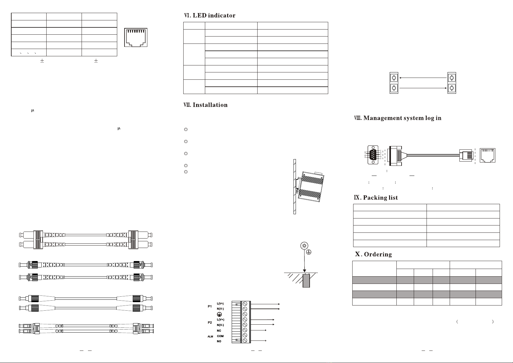
Notice: when connectfiber portA with fiber port Bby fiber patchcord, please
connect TX offiber portA withRX of fiber port B, and connect RX of fiber
port Awith TX offiber port B.
Fiber portA Fiber port B
7.6 Network portconnection
Connect the fibercord or network cable with relative network port, please
pay attention onRX & TXwhen fiber connection; the relative indicators
will be onor blinking.
LED Status Description
Network
port
indicator
ALM
green light on
green light off
green light on
green light blinking
green light off
red light on
red light off
P1~P2
green light blinking
green light on/off
RUN system running regular
system running breakdown
power normal
power breakdown or no power
link connection normal
link communication normal
link without connection or breakdown
with alarm signal output
without alarm signal output
ST port toST port fiberpatch cord
4
56
Pin No.
1
2
3
6
4578
MDI-X S
RX+
RX-
TX+
TX-
-
ignal
MDI S
TX+
TX-
RX+
RX-
-
ignal
18
Remarks: "TX " is "data transmit", "RX " is "data receive", "-" is empty
7.5 Relay alarm
Relay alarm is3-pin of theterminal block; itprovides power breakdown
alarm output. NCis normally close; when the device is breakdown,
NC means "short circuit"; otherwise itmeans "open circuit". NO is
normally open; whenthe device isbreakdown, NO means"open circuit";
otherwise it means"short circuit".
UT-62408F-8T2SC-BNF
UT-62408F-8T4SC-BNF
UT-62408F-8T-4GSC-BNF
UT-62408F-8T-4GP-BNF
2
4
-
-
100
Base-FX 1000
Base-X
-
-
4
4
10/100
Base-T(X)
8
8
8
8
100
Base-FX 1000
Base-X
SC
SC
-
-
-
-
SC
SFP
1. Single-mode dualfiber SC port/SFPslot is astandard configuration
for products abovementioned, with optional ST/FC.
2. The suffix"F"in "BNF"means 12/24/48VDC 10.8~52.8VDC
power input.
3. If thereis no model under requirement, orany questions about the
models, please contactUTEK.
1. Console port 115200 8-N-1
PIN3 TXD PIN4/5 GND PIN6-RXD
2. Web IP address 192.168.1.254
User name admin Password admin
This switch provides1 debug port which base onserial management
system. It adoptsRJ45 port, whichin the frontpanel. It canbe connected
with PC bythe cable in the package forsetting.
DB9 female RJ45
18
5.2
5.2.2
5.2.3
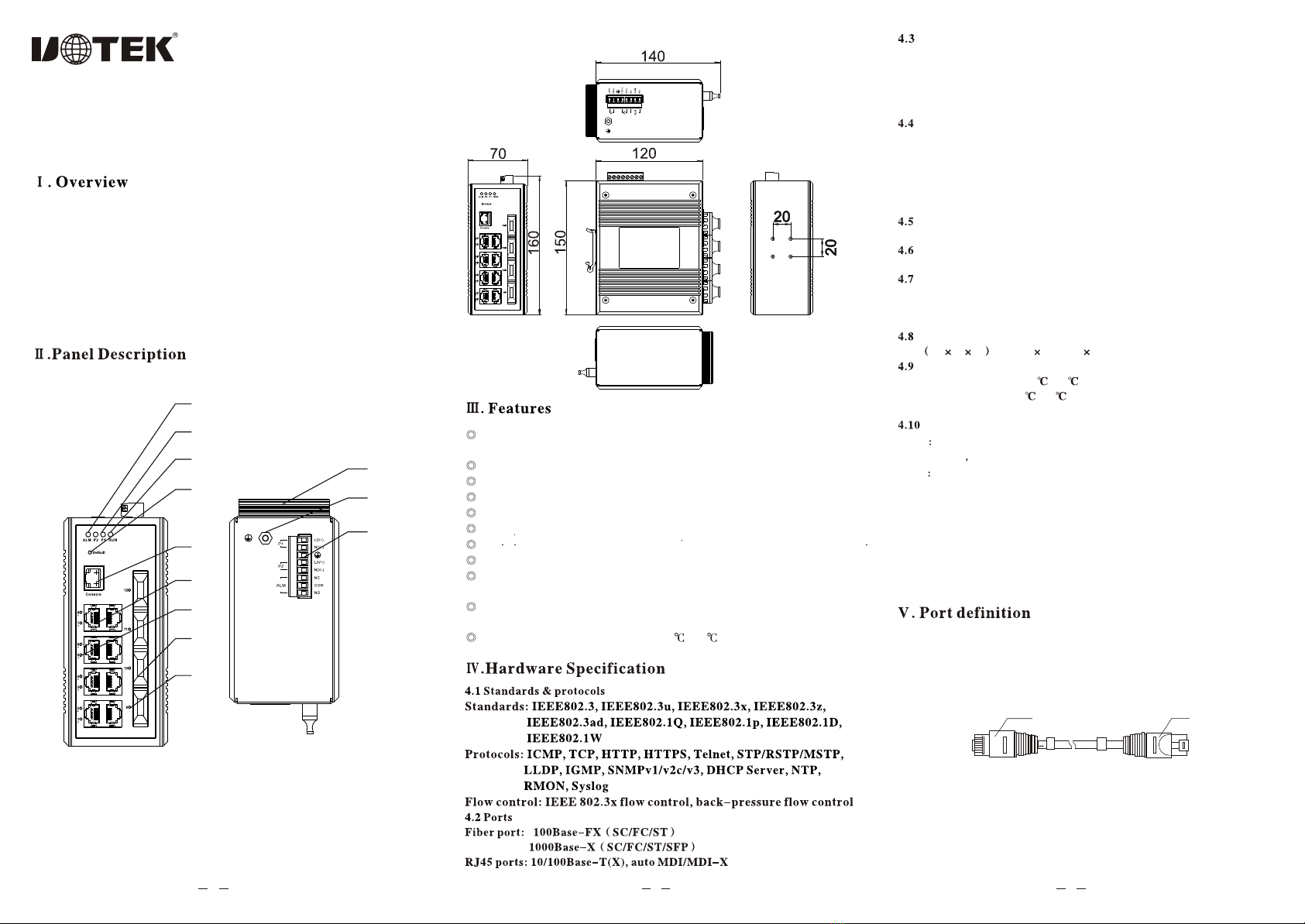
100/1000Base-F(X) fiber port
This series switchprovides 100/1000Base-(F)X fiberports; when usingRJ45
ports, it canbe connected with other Ethernet terminal devices through fiber
port by fiberpatch cord.
5.2.1 Fiber patch cord
According to thetransmission mode of light on fiber, there are multi-mode
fiber and single-modefiber. Thecentral glass coreof multi-mode fiber is thick
(50 or 62.5 m); it cantransmit light indifferent mode.The chromaticdispersion
is big, andthis causes limitation on frequency of transmission digital signal.
With this,the transmission distance of multi-mode fiberis short (mostly few
kms). The centralglass core ofsingle-mode is thin(9 or10 m), andit cantransmit
single mode light.The chromatic dispersionis small, itis good forlong distance
communication. Normally,the orange cable is multi-mode; the yellow cable is
single-mode.
Fiber port
Fiber port is a physical interf ace for fiber cableconnection. It adoptsthe principle
that when lightenter optically thinnermedium from opticallydenser medium,
the light willtotal reflection. Thereare four typesfiber port:
FC port: FC port isa round port with thread, metal style; it adopts metal cover
outside, use threadand nut tomatch and fix.
SC port: SC port isa standard squarestyle port; it adopts engineer plastics,
high temperature resistance,hard to oxidate.
LC port: LC port issimilar to SCport, but smaller than SC port;it adopts
modular jack, easyto operate.
ST port: ST port isa clip-on roundport.
Fiber patch corduse
SC port toSC port fiberpatch cord
FC port toFC port fiberpatch cord
Remarks: please don'tbend the fiberpatch cord when using.
LC port toLC port fiberpatch cord
7.1 Attention
To avoiddevice damage causingby wrong operationand personal injury,
please follow belowsteps:
Toavoid device damage by falling down,please put the device on stable
surface.
When the deviceis ready topower on, pleasemake sure thevoltage input
is wide voltagerange, and the positive/negative anodes of the power.
Toavoid the electric shock, make surethe device is in good ground
connection when operating.
Please do notopen the device case at any time.
Please keep awayfrom dusty and strong
electromagnetism interference environment.
7.2 DIN-Rail installation
Install the switchon guide rail, and then follow below
steps:
Step 1: Checkthe rail stability; put the switch rail slot
into the guiderail;
Step 2: rotatethe fix screw of the rail from center to
both sides inturn tightly,to make the guide rail plying-up
the vertical installcover slightly.
Step 3: Fixthe rail on the guide rail by screw,make sure therail and the
switch is verticaland stable.
7.3 Ground connection
Fix the groundwire on theground screw of the switch,
make sure goodconnection.
7.4 Power input
Plug the powerwire into theright position of 6-pin
terminal block, thenplug the terminalblock into
st
standard power inputport (1 power is P1L(V+),
nd
N(V-)input, 2 power is P2L(V+), N(V-) input,
supports V+, V- power voltage range 12/24/48VDC
(10.8~52.8VDC))
ground
connection
Earth
Relay alarm
st
1 power
nd
2 power
Ordering Port description Fiber port type