UTILCELL DP 100 User manual

User Manual


DP 100 User’s Manual
1
Table of Contents
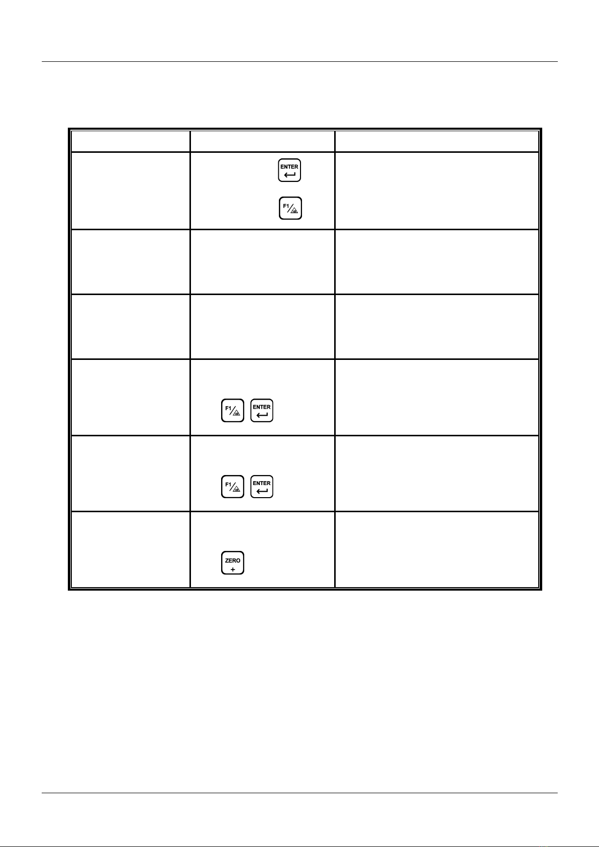
1Keypad Instruction .................................................................................................. 3
2Specifications .......................................................................................................... 4
3Front and Rear Panels ............................................................................................. 5
3.1 Front Panel ..................................................................................................................................5
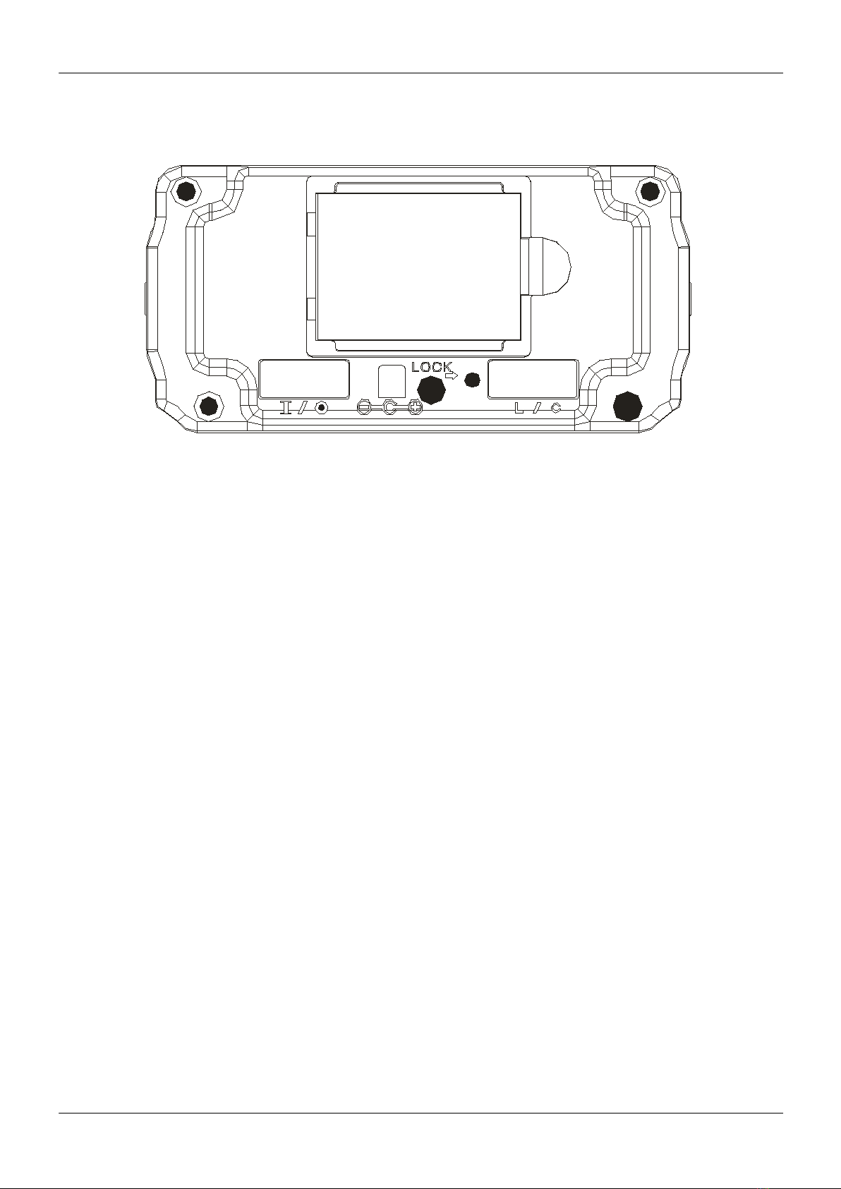
3.2 Rear Panel....................................................................................................................................6
4Installation .............................................................................................................. 7
4.1 Load Cell ......................................................................................................................................7
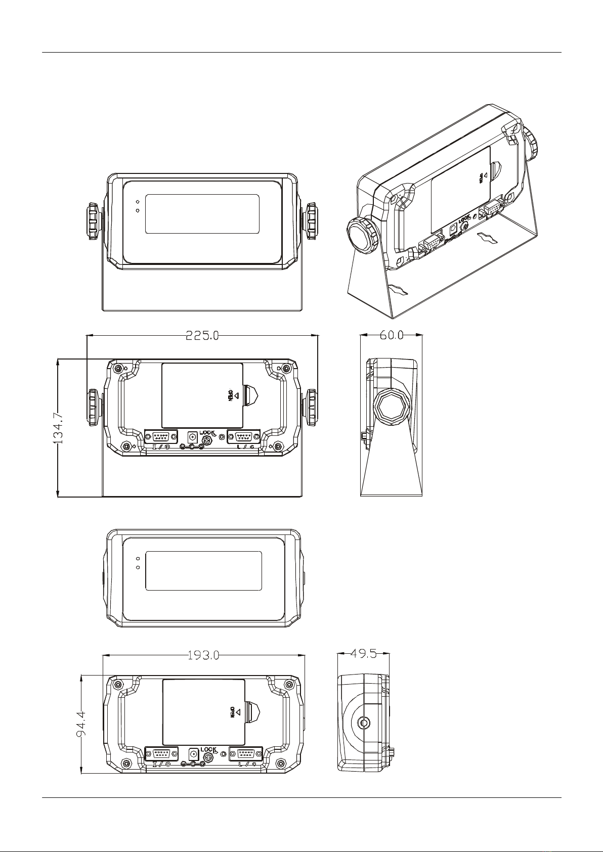
4.2 Dimensions ..................................................................................................................................8
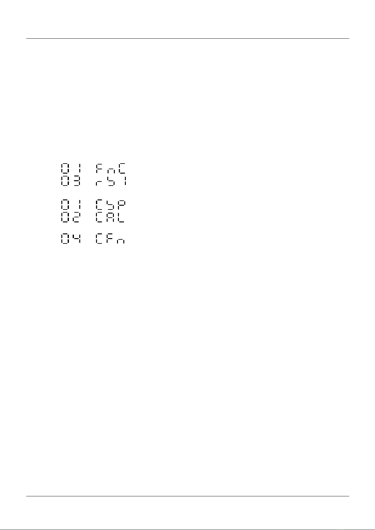
5External Function Parameter Setting ....................................................................... 9
5.1
External Function Setting ....................................................................10
5.2
RS-232 Setting .....................................................................................13
6Internal Calibration ............................................................................................... 18
6.1 Scale definition ....................................................................................19
6.2 Weight Calibration ...............................................................................22
6.3 Password Setting .......................................................................................................................23
6.4 Internal Function Setting .....................................................................24
6.5 Error Messages ..........................................................................................................................26
7Special Function .................................................................................................... 27
7.1 Animal Scale Setting ..................................................................................................................27
7.2 Dual Range Resolution Switch Function....................................................................................28
7.3 Manual tare function.................................................................................................................29
7.4 Resolution Switch Function.......................................................................................................29
7.5 Peak value function- HOLD........................................................................................................30
8Interface................................................................................................................ 31
9Maintenance ......................................................................................................... 32
9.1 Default Recovery for All Parameters.........................................................................................32
9.2 Default Recovery for General Function Parameters .................................................................32
9.3 Self-diagnosis Mode ..................................................................................................................32
9.3.1 Program Version Number...............................................................................................33
9.3.2 7-segment Display Testing .............................................................................................33
9.3.3 Keypad & Calibration Switch Testing .............................................................................33
9.3.4 A/D Conversion Value ....................................................................................................33
9.3.5 EEPROM Testing .............................................................................................................33
9.3.6 RS-232 Serial Output Interface Testing ..........................................................................33
Appendix 7-SEGMENT DISPLAY CHARACTERS .............................................................. 34
Version: March 2015
Software versions: 8075 or higher

DP 100 User’s Manual
2
!
SAFETY PRECAUTIONS
WARNING-SHOCK HAZARD
Due to the risk of electrical shock, this instrument must be
installed only by qualified personnel.
WARNING- SHOCK HAZARD
Due to the risk of electrical shock, the cover must be removed
only by qualified personnel.
WARNING
No ground or incorrect ground connection might cause
electric shocks and/or breakdowns.
CAUTION
Calibration and configuration must be performed only by
qualified personnel.
CAUTION
Turn off power before installing or disassembling.
CAUTION
The integrated circuits in the DP 100 are sensitive to
electrostatic discharge (ESD). Be sure to follow proper
procedures for transporting, storing and handling
ESD-sensitive components.
CAUTION
Never use alcohol or solvents to clean the indicator. These
chemical products could damage it
Make sure that water does not enter the indicator. It could
damage electronic components.

DP 100 User’s Manual
3
1Keypad Instruction
Function
Operation
Description
General Function
Setting
Press and hold
,
and then press
Refer to section 5 for details.
Weighing Parameter
Setting
Adjust calibration switch to
ON Refer to section 6.1 for details.
Calibration Adjust calibration switch to
ON Refer to section 6.2 for details.
Default Recovery
for All
Parameters
Adjust calibration switch
to ON, and then press and
hold
Refer to section 9.1 for details.
Default Recovery for
General Function
Parameters
While turning on with
countdown, press and
hold
Refer to section 9.2 for details.
Self-diagnosis Mode
While turning on with
countdown, press and
hold
Refer to section 9.3 for details.

DP 100 User’s Manual
4
2Specifications
Analog Specification
Load Cell Current : 5 V DC ±5% 60 mA (Up to four 350 Ω Load Cells)
Max. Load Cell Input Signal : 3 mV/V
Input Sensitivity : 0.15 µV/d or more
Conversion Rate : 120 times/s (max.)
Resolution : 20 bits
Digital Specification
Display : LCD, 6 digits, 25.4 x 10 mm (W x H), LED backlight
Display Frequency : 50 times/s (max)
Display Range : - 999 999 ~ 999 999
Min. Division : 1, 2, 5, 10, 20, 50
Decimal Point : 0, 0.0, 0.00, 0.000, 0.0000
Memory : Calibration parameter and function setting are all
stored in EEPROM.
Serial interface
RS-232 port for PC or printer connection
Power Requirement
Adaptor Spec : Input 230 V AC 50 ~ 60 Hz
Output 9 V DC / 1000 mA
Batteries : General AA batteries (5 pcs)
Max. Power Consumption :110 mA (with 4 Load Cells + backlight + RS-232
interface)
Others
Operation Temperature : 0 ~ 40 °C
Operation Humidity : < 85% R.H.
Dimensions (W ×D ×H) (mm) : 193 ×49.5 ×94.4 (indicator housing)
225 ×60 ×134.7 (mounting hardware included)
Weight : 1500 g

DP 100 User’s Manual
5
3Front and Rear Panels
3.1 Front Panel
Indication:
TARE : Tare mode
MOTION : Unstable weighing indication
M + : Accumulation mode indication
GROSS : Gross weight
PT : Manual tare
RANGE1/HOLD : Dual-range resolution indication: range 1/ HOLD indication
RANGE2 : Dual-range resolution indication: range 2
RANGE1 and HOLD description:
The led is ON by default. When using CNF-05 function (animal scale mode) or FNC-07 function (HOLD function setting) it
works as a hold led. In the other hand when using the multi-range mode, this led is used to indicate the range situation
where we are.
CFN-05 (animal scale mode) and FNC-07(HOLD function setting) functions can not work at the same time.
Keypad:
1) Power ON / OFF. Press and hold this key for 3 seconds to shut down.
2) Abort or exit when setting.
1) Weight re-zero.
2) Increase the flashing value by one when setting.
1) Eliminate the gross weight.
2) Decrease the flashing value by one when setting.
1) Switch Gross / Net weight shown on display.
2) Move the cursor leftward when setting.
1) Keypad function (FNC-02 & FNC-03).
2) Move the cursor rightward when setting.
Keypad function (FNC-02 & FNC-03).
Confirm key.

DP 100 User’s Manual
6
3.2 Rear Panel
5
1
234
1. Battery Case
2. RS-232 Plug
3. 9 V DC Power Input
4. Calibration Switch
5. Load Cell Connect Socket

DP 100 User’s Manual
7
4Installation
4.1 Load Cell
The indicator connector is a SUB-D 9 Male.
SUB-D 9
Connector Aerial
female
Pin Assignment
View from welded
side
4-Wire Load Cell
6-Wire Load Cell
PIN
SIGNAL
PIN
SIGNAL
1
SIG +
1
SIG +
2-3
EXC-
2
EXC-
4-5
EXC+
3
SEN-
6-7-8
SHIELD
4
SEN+
9
SIG-
5
EXC+
Bridge pins 2-3 (EXC- and SENSE-), 4-5
(EXC+ and SENSE+) and 6-7-8 (SHIELD)
6-7-8
SHIELD
9
SIG-
Bridge pins 6-7-8 (SHIELD)

DP 100 User’s Manual
8
4.2 Dimensions

DP 100 User’s Manual
9
5External Function Parameter Setting
Under general weight display status, press , and the screen will show:
Press key
Press key
Press to escape back to weight display status.
⇒External function setting
⇒RS-232 interface function

DP 100 User’s Manual
10
5.1
External Function Setting
Press
Select the desired
parameter code with
/
Press
Press to escape the setting
⇒Increase the flashing value by one
⇒Decrease the flashing value by one
⇒Move the cursor leftward
⇒Move the cursor rightward
⇒Save setting
⇒Abort setting or exit
*Parameter Code
⇒Key Disable
⇒DSP Update (Display Update)
⇒F1 Key Function Setting
⇒F2 Key Function Setting
⇒ENTER+F2 Function Setting
⇒Backlight Function Setting
⇒Beeper Setting
⇒HOLD Function Setting
⇒Auto-Switch-off Setting
The screen shows previous parameter setting.
Press . to finish and confirm your changes

DP 100 User’s Manual
11
External Function Parameter Setting
Parameter
Code Function
Setting Value
Default
Setting
Parameter
Description
FNC-00 Key disable
0000
↓
1111
0 ON 0000 is corresponding to (from left to right):
0000
1 OFF
FNC-01 DSP Update
0 No Limit
1
1 20 times/s
2 10 times/s
3 5 times/s
4 1 times/s
FNC-02
F1 Key
Function
Setting
0 Print (printing)
5
1 Units (units switch)
2 M+ (accumulation and printing)
3 MC (memory clearing)
4
Weight / Weight Accumulation / Time Accumulation
Display Switch
5 HR (high resolution switch)
6 Manual tare (Manual tare function)
FNC-03
F2 Key
Function
Setting
0 Print (printing)
1
1 Units (units switch)
2 M+ (accumulation and printing)
3 MC (memory clearing)
4
Weight / Weight Accumulation / Time Accumulation
Display Switch
5 HR (high resolution switch)
6 Manual tare (Manual tare function)
FNC-04
ENTER+F2
Function
Setting
0 Print (printing)
0
1 Units (units switch)
2 M+ (accumulation and printing)
3 MC (memory clearing)
4
Weight / Weight Accumulation / Time Accumulation
Display Switch
5 Resolution Conversion
6 Manual tare (Manual tare function)
FNC-05 Backlight
Setting
0
Auto Backlight On
(backlight on in operation only)
1
1 Backlight On (backlight always on)
2 Backlight Off
FNC-06 Beeper
Setting
0 Beeper off 1
1 Beeper on

DP 100 User’s Manual
12
FNC-07 HOLD function
setting
0 Disabled function
0
1 Mode 1
2 Mode 2
FNC-08 Auto Switch-
off
(minutes)
0 Disabled function
0
1 ~ 60 It works in a stable weight and no key pressed

DP 100 User’s Manual
13
The screen shows
previous parameter
setting.
Press to
confirm your
changes
5.2
RS-232 Setting
Press
Select the desired
parameter code with
/
Press
Press to escape the setting.
⇒Increase the flashing value by one
⇒Decrease the flashing value by one
⇒Move the cursor leftward
⇒Move the cursor rightward
⇒Save setting
⇒Abort setting or exit
*Parameter Code
⇒Information Pattern
⇒Transmission Method
⇒Transmission Rate
⇒Parity, Bit Length, Stop Bit
⇒Unstable or Overload
⇒Auto Transmission Condition
⇒Reserved
⇒Output Format
⇒Transmission Times
⇒Reserved
⇒Reserved

DP 100 User’s Manual
14
RS-232 Interface Function
Parameter
Code Function
Setting Value
Default Setting
Parameter
Description
RS1-00
Information
Pattern
(Please refer to
page 16)
0 Display Correspondingly
0
1 Gross Weight
2 Net Weight
3 Tare
4 Accumulated Weight
5 Numero of accumulations
6 Ticket
7 PT output
RS1-01 Transmission
Method
0 Continuous Transmission
0
1 Auto Transmission
2
Press or to transmit
3 Command Mode (no address)
4 Reserved
RS1-02 Transmission Rate
0 1200
3
1 2400
2 4800
3 9600
RS1-03
Parity,
Bit Length,
Stop Bit
0 N、8、1
No Parity
8 Bits Length
1 Stop Bit
01 O、7、1
Odd Parity,
7 Bits Length,
1 Stop Bit
2 E、7、1
Even Parity,
7 Bits Length,
1 Stop Bit
RS1-04 Unstable or Over
Load
0 Continue Output 0
1 Stop Output
RS1-05
Auto Transmission
Condition
0 Positive (over + 10d)
0
1
Positive / Negative
(over + 10d, under – 10d)
RS1-06
Reserved
Reserved
Reserved
Reserved
RS1-07 Output Format
0
Standard Format
0
1
UMC 600
2,3,4,5,6 Reserved
RS1-08 Transmission
Times
0
No Limit
4
1
1 times/s
2
2 times/s
3
5 times/s
4
10 times/s
5
20 times/s

DP 100 User’s Manual
15
RS1-09
Reserved
Reserved
Reserved
Reserved
RS1-10
Reserved
Reserved
Reserved
Reserved

DP 100 User’s Manual
16
Transmission Format
RS1-00
⇒
0 ~ 3
S T , G S , + 1 2 3 4 . 5 6 g CR LF
Header 1 Header 2 Weight Data (8 digits) Unit Terminators
Header 1
ST: Stable Weight / US: Unstable Weight / OL: Weight Overload
Header 2
GS: Gross Weight / NT: Net Weight / TR: Tare
Weight Data (8 digits)
The first digit of weight data represents “+ / -“ indication for weight value. The other 7 digits,
including decimal point, represent the weight value. If the weight is over load (Header 1: OL),
the screen turns into “blank” except “+ / -“ indication and decimal point.
Unit
kg, lb, t or “blank”
Terminators
CR and LF are data termination code.
RS1-00 = 4
T N , 1 2 3 CR LF
RS1-00 = 5
RS1-00 = 6
T W , + 1 2 3 4 . 5 6 k g CR LF
D A T E : 2 0 X X / X X / X X CR LF
T I M E : X X : X X : X X CR LF
G R O S S : + 1 2 3 4 . 5 6 k g CR LF
N E T : + 1 2 3 4 . 5 6 k g CR LF
T A R E : + 1 2 3 4 . 5 6 k g CR LF
T N : X X X CR LF
T W : + 1 2 3 4 . 5 6 k g CR LF

DP 100 User’s Manual
17
RS1-00 = 7
Command Mode
Command Function Command Function
READ / RW Weight Reading CT Tare Clearing
ZERO / MZ Weight Re-zeroing Rl Weight Accumulation
TARE / MT Gross Weight Deducting Rm Times Accumulation
NTGS Gross / Net Switch AT
Weight and Times
Accumulation
MG Gross Weight Indicating DT
Weight and Times
Accumulation Clearing
MN Net Weight Indicating
After setting the commands mentioned above, it’s necessary to add the termination code “CR
(0DH) and LF (0AH)”.
If the command is not correct, it will reply “E” + “Command Unidentified”.
D A T E : 2 0 X X / X X / X X CR LF
T I M E : X X : X X : X X CR LF
G R O S S : + 1 2 3 4 . 5 6 k g CR LF
N E T : + 1 2 3 4 . 5 6 k g CR LF
T A R E : + 1 2 3 4 . 5 6 k g CR LF
P T : + 1 2 3 4 . 5 6 k g CR LF
T N : X X X CR LF
T W : + 1 2 3 4 . 5 6 k g CR LF

DP 100 User’s Manual
18
6Internal Calibration
Adjust calibration switch to “ON”. The screen displays:
After 2 seconds
Press
Press
Press
Press
Adjust calibration switch back to “LOCK”.
⇒Scale definition
⇒Weight Calibration
⇒Internal Function Setting
Table of contents
Popular Accessories manuals by other brands

Anritsu
Anritsu MA24 A Series Operation manual

Oregon Scientific
Oregon Scientific Wireless Outdoor Temperature and Humidity Sensor THGR 238... user manual

SICK
SICK TiM8 DistanceGuard Series operating instructions

Milesight
Milesight EM400-UDL user guide

Microsonic
Microsonic lcs+340/DD operating manual

SIGMA TEK
SIGMA TEK BWH 011 instruction manual