Utile LW401 Guide

The Utile Engineering Co. Ltd. 16/09/03
Irthlingborough, Northamptonshire. England
Tel: +44 (0) 1933 650216
Fax: +44 (0) 1933 652738 1 IC144
Installation
Operation
Maintenance Instructions
Model LW401
Blower / Vacuum Pump
with manual 4 way valve
Serial Number
Site Location
Installation Date

The Utile Engineering Co. Ltd. 16/09/03
Irthlingborough, Northamptonshire. England
Tel: +44 (0) 1933 650216
Fax: +44 (0) 1933 652738 2 IC144
Page
General …………………………………………………………………………………….. 3
Operating Principle …………………………………………………………………………… 3
Health and Safety …………………………………………………………………………… 4
Technical Specification …………………………………………………………………………… 5
Packaging …………………………………………………………………………………….. 5
Storage …………………………………………………………………………………….. 5
Handling …………………………………………………………………………………….. 6
Installation …………………………………………………………………………………….. 6
Pre Start-up Checks …………………………………………………………………………… 8
Start-up …………………………………………………………………………………….. 8
Protective Devices …………………………………………………………………………… 8
Operating Notes …………………………………………………………………………… 9
Stopping Procedure …………………………………………………………………………… 9
Lubrication …………………………………………………………………………………….. 9
Maintenance …………………………………………………………………………………….. 10
Troubleshooting …………………………………………………………………………… 11
Check Blade Wear …………………………………………………………………………… 11
Blade Inspection …………………………………………………………………………… 12
Reassembly after Blade Inspection ………………………………………………………… 12
Cylinder Renewal …………………………………………………………………………… 12
Change Bearings and Seals …………………………………………………………………. 12
Reassembly …………………………………………………………………………………….. 13
Spare Parts …………………………………………………………………………………….. 14
After Sales Service …………………………………………………………………………… 14
Spare Parts List …………………………………………………………………………… 15
Warranty …………………………………………………………………………………….. 16
Warning
Read the installation and maintenance information before commencing work on this equipment. Your attention is
drawn to the health and safety information on page 4. Until the equipment into which the machine has been
incorporated and the said equipment declared to be in conformity with the Machinery Directive, they must not be
put into service.
Foreword
The LW rotary blowers and vacuum pumps have been developed based on many years of experience in the
compressor and vacuum pump industry. Using modern design techniques and production methods coupled with
rigorous testing and high quality standards ensure these of machines have a long, efficient and reliable service life.
These operating instructions have been written for all personnel who have responsibility to the machine, it contains
all the necessary information required for the machine to have a long trouble free service life. This manual must be
stored near the machine and read before attempting any work on it.
Ensure that all operation and maintenance is only performed by competent and trained personnel and any repairs
use only original parts from the manufacturer.
Contents
Contents
Foreword
Contents
Foreword

The Utile Engineering Co. Ltd. 16/09/03
Irthlingborough, Northamptonshire. England
Tel: +44 (0) 1933 650216
Fax: +44 (0) 1933 652738 3 IC144
General
The normal routine of running the machine is very simple. If it is carried out strictly at all times, many years of
trouble free service can be expected.
We emphasise two points of paramount importance-
1. Filtration of incoming air of gas 2. Lubrication
If possible provide a logbook so that the operator can enter daily readings. After several months a record will show
whether the machine is performing as it did originally. If readings are to be taken the following are all that is
required. Inlet and outlet air temperatures, suction conditions and oil drip rate.
A typical layout for the log book is shown in the table below.
Machine Log Book
Date Inlet Gas Temp. Discharge Gas Temp. Inlet Conditions Oil Drip Rate.
Operating Principle
Rotary sliding vane compressors and vacuum pumps are multi-cell machines, which work on the displacement
principle. They provide a constant, low-pulsation supply of air or gas.
The machines have a cylindrical bored housing. The rotor, which is also cylindrical, is fitted eccentrically in the
cylinder so that a crescent-shaped working chamber is formed. Movable rotor vanes are fitted in the longitudinal
grooves in the rotor; centrifugal force and the force of the air or gas presses the blades against the cylinder-housing
wall when the rotor turns.
The vanes divide the crescent-shaped working chamber into cells of different sizes. As the rotor turns, the cell
volume on the intake side increases, and the cell draws air in at low pressure, at which point is open to the intake
delivery line. As the rotor continues to turn, the cell is closed (see fig 1) and the volume of the cell decreases. This
causes the enclosed air or gas to be compressed (see fig 2) and forced out through discharge delivery line under
atmospheric pressure.
The machine can only be run in one direction, which is indicated by an arrow on the cylinder. The direction of
rotation must not be reversed.
Fig. 1
Discharge Intake
Fig. 2
Discharge Intake
General
Operating Principle

The Utile Engineering Co. Ltd. 16/09/03
Irthlingborough, Northamptonshire. England
Tel: +44 (0) 1933 650216
Fax: +44 (0) 1933 652738 4 IC144
Read the installation and operating instructions carefully.
Rotating machinery and pressurised components, which may contain toxic, flammable or otherwise hazardous
media are potentially dangerous equipment if not operated and maintained correctly. It is imperative that all users
of such equipment fully educate themselves to the potential dangers and satisfy themselves that the personnel
responsible for installing, testing, commissioning, operating and maintaining the plant are competent to do so.
Instruction manuals are provided for guidance but must assume some basic level of competence by users. If there
are any doubts or ambiguities concerning correct procedures, ask Utile Engineering. DO NOT TAKE RISKS.
Certain machinery can generate high levels of noise which can be harmful if exposed to it for lengthy periods of
time. Various codes of practice are in existence and users must ensure that adequate precautions are taken to
prevent a health hazard to employees or third party.
Equipment with internal pressures above or below ambient pressures can create a hazard. Before attempting to
investigate problems, service or maintain equipment, it must be safely depressurised or pressurised to ambient
conditions. Also since the gaseous medium may be flammable, toxic, corrosive or otherwise hazardous it may be
necessary to purge the installation with an inert gas, such as nitrogen. Special precautions are necessary for
certain gases and the user must ensure that adequate procedures are implemented.
Moving parts of machinery must not be touched and all such parts must be adequately guarded. Suitable guards
are provided and must be securely retained in position at all times.
Before commencing maintenance, servicing or making other adjustments, the prime mover and other equipment
must be isolated electrically or otherwise immobilised to prevent accidental start-up. In this vein, a fully qualified
electrician should carry out all electrical work and all electrical equipment should be isolated before it is touched
and pneumatic or hydraulic controls depressurised and made safe. Procedures must also exist to ensure that
electrical or other inputs cannot be restored accidentally during the maintenance or service period.
Safety trips, emergency stop-buttons and other such devices (if fitted) are to be checked regularly to ensure that
they continue to function correctly and will protect the installation and personnel in the event of an emergency.
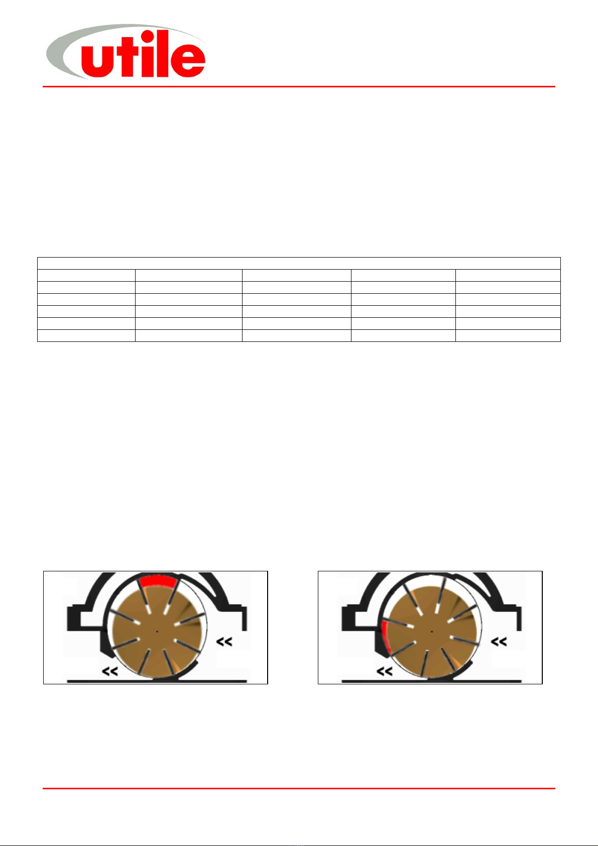
NO attempt should be made to touch the machine whilst it is rotating. Particular care is needed when checking
rotor clearances. Any movement of rotors may trap fingers.
Most machines, certain pipes and ancillaries become hot during operation whilst certain machines with sub-zero
inlet temperatures may result in very cold surfaces. If it is possible for personnel to come into contact with such
surfaces unknowingly or accidentally they should be guarded.
If severe vibration is observed, the cause of this should be immediately investigated and the situation rectified.
Excessive vibration can lead to fatigue and other failures. Similarly, if during operation a significant change is
noticed in the level of vibration, noise, temperature or any other parameter, the cause of such changes must be
determined, and the cause rectified. Inlet filters must be inspected regularly so that liquid or debris is not allowed to
enter the machine, which could cause damage and consequently injury to personnel.
During routine maintenance, coupling alignment should be checked for misalignment.
Only approved lubricants must be used and quantities, etc must be checked regularly.
Before restarting after servicing, all nuts, set screws, etc must be checked for tightness, check all joints, for leaks
and carry out purging as necessary before introducing the process gas. Also, before start-up, check the machine
inlet and outlet isolating valves are open both non-return valves (if fitted) are the correct orientation.
Adjacent pipework and equipment must not impose undue forces and moments on the machinery flanges.
All welding work must be carried out be an approved gas coded welder.
In order to prevent reverse rotation of machines, it is ESSENTIAL that a non-return valve be installed in the inlet
pipework. Otherwise a hazardous situation can arise during a normal shutdown or if the prime mover power supply
is interrupted for a period of time.
The environment around the installation may need to be monitored in order to detect gas leaks etc., and
consideration must be given to the installation of gas detecting equipment, and the class of electric equipment.
All personnel working in or passing through the area should be adequately warned by signs and trained to exercise
appropriate safety precautions. Ensure the correct personal protective equipment is worn at all times.
Health and Safety

The Utile Engineering Co. Ltd. 16/09/03
Irthlingborough, Northamptonshire. England
Tel: +44 (0) 1933 650216
Fax: +44 (0) 1933 652738 5 IC144
Technical Specification
The model, machine serial number, year of manufacture, temperature class and zone rating for the machine
appear on the machine data plate, other machine data can be found in the following table.
Units LW401
Maximum Pressure Bar 1.75
Maximum Vacuum kPa 95
Speed – Maximum R.P.M. 1300
Speed - Minimum R.P.M. 900
Volume at 1 Bar at Max. Speed (Air) m3/hr 387
Capacity at 50 kPa at Max. Speed (Air) m3/hr 430
Absorbed Power at 1 Bar at Max. Speed (Air) kW 16.3
Absorbed Power at 50 Kpa at Max. Speed (Air) kW 9.7
Maximum Ambient Temperature °C40
Surface Temperature at Max. Press. at Max. Speed (Air) °C170
Surface Temperature at Max. Vac. at Max. Speed (Air) °C190
Moment of Inertia kg m20.24
Noise Level at 1 metre db (A) 90
Weight kg 140
Note: Machine must not be used on any other gas than originally specified. Utile Engineering must be consulted if
traces of any other gas are introduced into the machine.
Packaging
The packaging conforms to the relevant regulations. The symbols used on the
packages are shown on the right.
The machines are bolted down on a pallet and therefore should not move during
transportation and either cased or shrink wrapped for general protection. The
ancillary components are packed suitably within the case. The packaging and
contents should be received in good condition. When unpacking do not remove
the inlet/outlet protection covers.
The contents should be inspected against the advice note, notify Utile Engineering
within 3 days of any items, which are damaged or are missing, followed by a written claim within seven days of the
goods being delivered.
Storage
If the machine is not required for immediate installation, the machine should be stored in a clean, dry area
protected from the weather. The intake and discharge port covers must remain in position until the machine is
installed. We recommend that the shaft be turned a few revolutions by hand to ensure the machine is running free
every month until the machine is installed.
The green protective coating on the shaft remains effective for approximately 1 year. If the machine is stored for a
longer period of time, the coat must be renewed.
Technical Specification
Packaging
Storage
Top /
This Way Up
Fra
g
ile
Nameplate Data
Machine Model eg LW401
Machine Serial Number
(Always quote this in
correspondence)
Lo
g
o
Temperature Classification
450°C – T1 300°C – T2
200°C – T3 135°C – T4
1
00
°
C
– T
5
85
°
C
– T
6
CE Markin
g
Contact address & numbers
Zone Rating
0 – Very High Protection - Gas Area
1 – High Protection - Gas Area
2 – Normal Protection - Gas Area
Year of
Manufacture
Ex
Mark
Equipment Group
I – Mines
II – Surface Indus
Gas/Dust
G – Gas
D - Dust
Protection Category
1–V.High Protection
2–High Protection
3–Normal Protection

The Utile Engineering Co. Ltd. 16/09/03
Irthlingborough, Northamptonshire. England
Tel: +44 (0) 1933 650216
Fax: +44 (0) 1933 652738 6 IC144
Handling
Skilled personnel working in accordance with safe working practices must
carry out the lifting of machines. Before lifting the correct equipment must
be available. Cranes, jacks, slings, and lifting beams must be capable of
carrying the weight of the machine to be lifted. The lifting eyebolt situated in
the top of the cylinder and a crane hook must be used when lifting or
moving the machine (see fig 3). Do not use the machine ports or the shaft
extension for lifting or moving the machine.
For weights see table in Technical Specification.
Installation
Before commencing installation, a site specific risk assessment, method statement and hazard identification list
must be completed and adhered to. All work must be carried out in a safe area. Utile Engineering trained personnel
or those trained to an equivalent standard should carry out installation, any claims for damage due to faulty
installation will be void. The machine is delivered ready to be connected, with only the removal of the intake and
discharge protection covers. All warning labels and instructions must be observed and retained with the machine.
Before installation, ensure there is no damage to the machine and that it turns freely by hand.
Typical tools required for installation include: -
Set of spanners Pipe Wrenches Set of screwdrivers Hacksaw
Set of Allen Keys Hammer / mallet Drill (low voltage)
Typical bolt tightening torques are: -
Bolt Tightening Torques
Size Torque Size Torque
M4 4.00 Nm M12 70.00 Nm
M5 6.00 Nm M16 100.00 Nm
M6 10.00 Nm M20 150.00 Nm
M8 18.00 Nm M24 250.00 Nm
M10 40.00 Nm
Location
The machine should be installed in a clean, dry, well-ventilated area. Allow adequate space and facilities for
service, inspection and future expansion. A minimum of 0.75m of working space around the machine is
recommended. Adequate space around the motor and machine, particularly any fan inlets, is also necessary to
facilitate cooling airflow. Where several machines are installed in close proximity, care must be taken to ensure
there is no recirculation of exhausted warm air.
Foundation
Simple slab type foundations, designed for static loadings only are satisfactory. The foundations should raise the
machine to a reasonable height above the floor for convenient service and inspection. The use of anti-vibration
mounts between the base and foundation are recommended, these absorb the vibrations generated by the rotating
parts of the machine and insulate it against any vibration in the surrounding environment. Ensure that the anti-
vibration mounts are evenly loaded. Foundation bolts should fix the base.
Electrical Supply and Connection
The voltage rating of the supply must be compatible with the motor and the fittings. All electrical installation must be
carried out by a qualified electrician and in accordance with current regulations and within the framework of the
Electricity of Work Regulation 1990. Ensure all electrical connections, plugs, sockets etc are secure before
switching the supply on.
Earthing
It is important that the motor enclosure is soundly earthed by metallic earth continuity conductor, or by separate
earth bonding, but in all cases the installation must be made and tested and approved for this feature by a qualified
installer before the supply is applied to the motor.
Handling
Installation
Fig. 3

The Utile Engineering Co. Ltd. 16/09/03
Irthlingborough, Northamptonshire. England
Tel: +44 (0) 1933 650216
Fax: +44 (0) 1933 652738 7 IC144
Fitting Pulleys and Couplings
These should be bored to our standard limits (details supplied upon request) and fitted to the shaft with a screwing
motion. On no account should they be driven on. Tapping of fitments onto the machine shaft with a hammer or
mallet, causes bearing damage. This results in an increase in bearing noise and a significant reduction in bearing
life. Attention should be paid to the guarding of all moving parts.
Drive Alignment
The rotor shaft must always be horizontal. There are three basis modes of misalignment, these are angular, parallel
and axial (shown in fig. 4).
Flexible Coupling
1. Remove any dirt, oil, etc. from all mating surfaces. Place bush in hub and
match half holes on both shafts.
2. Place setscrews loosely in threaded holes. Mount assembly in desired
position on shafts.
3. Tighten setscrews. Place disc/flexible coupling in position, and bring the
shafts together obtaining the manufacturers assembled length for the
coupling given in their instructions.
4. To check for angular alignment: (see fig. 5)
Rotate the coupling through 90°and measure the distance between the
faces. Repeat adjusting the shafts until four identical measurements are
obtained.
To check for parallel alignment: (see fig. 5)
Place a straight edge across the coupling. The hubs will be in correct
alignment when the straight edge contacts the 4 points squarely.
Drive Belts
1. Remove any dirt, oil, etc. from all mating surfaces. Place bush in hub and
match half holes on both shafts.
2. Mount assembly in desired position on shafts ensuring both shafts are
parallel and in correct alignment, use a straight edge, a correctly aligned
drive will contact both pulleys squarely (see fig. 6).
3. Fit driving belts. Measure span of belts between tangent points of the two
pulleys. A deflection of 1.5mm is obtained for
every 100mm of the measured span. Compare
the deflection force required with the table. If
the force required is according to the table
then the tension is suitable. Too little force
indicates under-tension and visa-versa.
4. The belts should be tensioned towards the
high side, to allow for the tension drop after the belts have been run-in. Belt
tension should be checked daily in the first week after installation/renewal.
Warning
Excessive tension on the pulleys will damage the bearings and lead to probable shaft rupture.
Belts, which become charged electrostatically, must not be used in hazardous atmospheres.
Belt
Section
Force Required to
deflect belt 1.5mm per
100mm span (kgf)
SPZ 0.5 to 0.8
SPA 1.0 to 1.5
SPB 2.0 to 3.1
SPC 4.1 to 6.1
Parallel Alignment Check
Angular Alignment Check
Fig. 5
Angular Misalignment Parallel Misalignment Axial Misalignment
Fig. 4
Correct pulley alignment
Span Distance
Fig. 6
Installation

The Utile Engineering Co. Ltd. 16/09/03
Irthlingborough, Northamptonshire. England
Tel: +44 (0) 1933 650216
Fax: +44 (0) 1933 652738 8 IC144
Pipework
The connecting pipework must be completely clean, dry and free from internal rust or scale.
When fitting the intake and discharge pipework it is essential that adequate supports be provided and that it is
properly aligned to prevent excessive strain being placed upon the machine, flexible pipe should be placed in
the pipeline to remove this strain.
During installation care must be taken to ensure that no foreign matter enters the machine or serious damage
may result.
An intake filter should be fitted into the intake side to prevent any particles from entering the machine.
Use P.T.F.E. tape only as a jointing medium since surplus from jointing compounds will damage the blades if
drawn into the machine.
When the machine is delivering into or exhausting from a receiver, or working with a system having a large
storage capacity, it is essential to fit a non-return valve in the pipework, preferably on the discharge side to
prevent the machine from running in reverse on shutdown.
Arrange both the intake and discharge pipework so that any condensate flows away from the machine.
If user is installing their own protective switches and other devices these must be suitable for operation in the
zone classified.
All pipework and fittings must comply with IGE/UP/2 or the national standard for the country of installation.
Pre Start-up Checks
Before starting the machine for the first time after installation, maintenance or after a long downtime, make the
following checks: -
9Ensure all the anchor bolts for the machine, base and motor are securely fastened.
9Check that the machine is free running by turning the shaft by hand through a few revolutions.
9Flick start the motor to check that the direction of rotation agrees with the arrow on top of the machine cylinder.
Note this should be completed with the coupling/drive belts removed.
9Recheck coupling/drive alignment and retension (see page 7).
9Ensure all equipment is installed and earthed in accordance with current legislation.
9Check all piping connections.
9If the system is to be pressure tested, all gauges and pressure switches must be isolated or removed.
Maximum purge or pressure test is 1.50 times the working pressure.
9Check all protective devices ensuring they are working correctly.
9Ensure personnel are adequately protected from accidental contact with all dangerous equipment.
9Fill the oil tank with Shell Rimula 15W/40 oil or equivalent (see lubrication), prime the oil lines to the machine.
9Instruct the operating personnel that the machine is operational.
Protective Devices
All pressure and temperature switches must be set and tested at the desired set point by simulating the set point in
actual operation.
With the machine running at the duty pressure after warming up, adjust the discharge temperature switch
downwards to actuate and stop the machine. Reset the switch at the cut out temperature plus 10oC - 15oC in order
to avoid false tripping from small and reasonable increases above normal levels.
Adjust the high pressure cut out switch in the same manner and reset at working pressure plus 10%.
At the end of the commissioning run, remove the cone shaped mesh strainer from the inlet, clean and replace.
If a large amount of debris has been collected run a further 2 hours repeating the process until the filter stays clean.
Start-up
Proceed as follows: -
i. When starting compressors the intake valves are fully open. Compressors can usually be started against
normal discharge pressure. When starting vacuum pumps the intake valve can be closed to reduce the
starting power and then slowly opened as the machine reaches operating speed.
ii. Some compressors are piped with a manual start-up bypass valve from discharge to intake, for pressure
equalisation during startup, This must be fully opened before startup.
iii. Start the drive motor and bring the machine up to operating speed.
iv. When full speed is reached slowly close the manual start-up bypass valve.
v. Check and adjust the lubricator drip rate to that indicated in the lubrication section.
vi. Check all protective devices and controls making sure they are working correctly.
Pre Start-up Checks
Protective Devices
Start-up

The Utile Engineering Co. Ltd. 16/09/03
Irthlingborough, Northamptonshire. England
Tel: +44 (0) 1933 650216
Fax: +44 (0) 1933 652738 9 IC144
Operating Notes
Daily, check the oil drip rate through the indicator. Fill the oil tank.
After the initial running in period, check the belt tension. Belt squeal denotes a loose belt that requires
tightening.
Inspect the filter fitted to the inlet, regularly clean and renew the element when necessary.
Excessive discharge temperature for normal operation as indicated by the rise in temperature shown in the
log book indicates inadequate cooling, faulty lubrication or a dirty intake filter. The machine should be
stopped and inspected.
Check the machine internally for wear every 10,000 running hours. (see Inspection and Service)
The blade depth should be checked after the initial 2,000 running hours and thereafter every 5,000 running
hours for wear and renew if the rubbing tips have worn to a depth of 65mm. (see Check Blade Wear).
Condensate if allowed to enter the machine can cause severe blade wear.
If adjustment of the oil drip rate is required (see lubrication).
Stopping Procedure
Proceed as follows: -
i. Trip out or Stop the drive motor.
ii. If machine is on a standby service, run for a few minutes each week.
Lubrication
Prime oil pipes prior to initial start and every time
machine is dismantled for service, as serious damage
will occur if the machine runs unlubricated. The
lubrication system is a total loss system, recycling of oil
is not recommended
Standard lubricator drip rate is 28 - 30 dpm each feed at
1000rpm using the standard S8899 drip indicators and
can be increased / decreased pro-rata with the speed.
The recommended grade of oil is Shell Rimula 15W/40 the typical physical characteristics are shown above: -
Oil pump adjustment
The pump is adjusted to the correct flow rate when despatched from
our works. If it found necessary to alter the oil feed, then proceed as
follows using fig. 7:
1. Loosen off locking nut (8) from adjusting screw-retaining
bracket.
2. To decrease flow, back off external nut (9) towards shoulder of adjusting screw.
To increase flow, tighten external nut (9) onto adjusting screw-
retaining bracket.
3. Tighten locking nut (8) onto adjusting screw-retaining bracket.
Lubricator Maintenance
Refill the oil reservoir regularly to ensure that the oil level is not allowed to fall to a point where air can be drawn
into the oil pump. Use only clean, new oil of the recommended grade. At least once a year, or if the machine has
been out of use for a long period, the oil pump must be thoroughly flushed out with petrol/kerosene to clear any oil
residues that may have solidified in the control ducts. For this operation we recommend the following procedure: -
1. Stop the machine and disconnect all the oil pipes from the oil pump.
2. Remove oil reservoir, drain oil and wash out with petrol/kerosene. Drain again ensuring all oil residues are
removed. Replace reservoir and reconnect the oil feed pipe (oil reservoir to oil pump).
3. Fill the reservoir with petrol/kerosene to cover oil filter element. Loosen oil feed pipe connection at oil pump
end until all air has been expelled. Re-tighten pipe.
4. Start the machine under no load condition and run until petrol/kerosene begins to flow from oil pump
discharge points. This operation takes approximately 10 – 15 minutes and providing the machine is run
under no load conditions, no damage will occur.
5. Stop machine, drain oil reservoir and fill with recommended grade of oil. Ensure all oil pipes are primed.
Reconnect oil delivery pipes (oil pump to machine) and start up.
Operating Notes
Stopping Procedure
Lubrication
Fig. 7
Operating Notes
Stopping Procedure
Lubrication
SAE Viscosity Grade 15W/40
Kinematic Viscosity
@ 40ºC cSt
100ºC cSt (IP71)
100.1
14.5
Viscosity Index (IP226) 135
Pour Point ºC (IP15) -27
Density @ 15ºC kg/l (IP365) 0.890
Flash Point (PMCC) ºC (IP34) 226
Sulphated Ash % wt (IP163) 1.1
Total Base Number mg KOH/g (IP276) 8.0

The Utile Engineering Co. Ltd. 16/09/03
Irthlingborough, Northamptonshire. England
Tel: +44 (0) 1933 650216
Fax: +44 (0) 1933 652738 10 IC144
Maintenance
Fully trained and competent staff must carry out any maintenance work. Utile Engineering offers contract
maintenance services if required contact our service department.
When carrying out any maintenance and inspections always follow the health and safety guidelines on page 4.
A regular correct maintenance plan is essential to good operational reliability and a long service life for your
machine. As operating conditions vary, no exact timings can be specified for wear checks, repairs and inspections,
however the following plan can be used as a guide until time scales to better suit the machines environment are
found.
The machine, ancillaries and surrounding area should be kept as clean as possible.
Ensure all items are properly held and supported during all aspects of maintenance as not to pose a problem for
health and safety. Observe all lifting points and apply care when handling the equipment.
Ensure all machines and associated pipework have cooled down sufficiently before touching and attempting any
maintenance.
Typical tools required for maintenance include: -
Set of spanners Pipe Wrenches Circlip Pliers
Set of screwdrivers Vernier Gauge / Micrometer Two-leg Pulley drawer
Set of Allen Keys Hammer / mallet Feeler Gauges
Typical bolt tightening torques can be seen on page 6.
New gaskets must be fitted every time the machine is dismantled.
Bearings and seals are recommended to be replaced after 15000 operating hours or 2 years whichever is sooner.
Blades must be replaced regardless of wear after 20000 operating hours as failure due to fatigue could cause
serious damage.
After maintenance the machine and equipment must be treated, as new and all pre-commissioning checks should
be made. Install all protective devices and controls properly after completion of work. Ensure all cabling, unions and
guards are correct, secure and in place. Dispose of any used oil and cleaning solutions as prescribed by law.
MAINTENANCE PLAN
DAILY CHECKS QUARTERLY CHECKS
TASK CHECK TASK CHECK
Check / Fill lubricator reservoir Check machine for blade wear.
Check Belt condition/Tension (Hourly for
running in period).
Check control panel for wiring, cleanliness and
function of all panel features. (if applicable)
Drain all vessels, condensate traps, outlet
filters manually
Check function of emergency stop button and
local motor isolator. (if applicable)
Clean inlet filters (Daily for 1st week). Check motors for excessive vibration and
damage.
Check function of pressure gauges.
WEEKLY CHECKS Check function of non-return valves
Check lubricator drip rate Check function of pressure relief valves
Check belt condition / tension
Clean inlet filters (After for 1st week).
YEARLY CHECKS
MONTHLY CHECKS Clean lubricator and oil lines
Check function and operation of all valves. Check flanges and joints for leaks.
Check differential pressure across filters (clean
and replace if necessary).
Clean internally vessels, condensate traps,
filters (including elements).
Check function and operation of autodrains /
condensate lines.
Inspect machine internally (at least once a
year)
Clean fins on machine and motors
Maintenance

The Utile Engineering Co. Ltd. 16/09/03
Irthlingborough, Northamptonshire. England
Tel: +44 (0) 1933 650216
Fax: +44 (0) 1933 652738 11 IC144
Troubleshooting
The following table shows some typical problems and the remedies.
Note: If assistance is required in determining and correcting the fault with the machine then contact our service
department.
1. Check Blade Wear
When carrying out any maintenance and inspections always follow the
health and safety guidelines on page 4. Fully trained and competent staff
must carry out any maintenance work.
1.1 Carry out the following procedure after the first 2,000 running
hours and repeat every 5,000-hour interval. Record all
measurements.
1.2 With the pump stationary and with the system drained, remove the
plug on the side of the machine cylinder and insert into the hole
beneath a pointed measuring rod 6mm dia x 150mm long until
contact is made with the rotor (see fig. 8). Scribe a mark on the
rod. Slowly rotate the shaft by hand until the rod drops onto the tip
of the blade, scribe a second mark on the rod. Measure the
amount of movement and renew the blades if this exceeds 6mm.
Replace the plug or eyebolt.
SYMPTONS CAUSES REMEDIES
Machine revolves in wrong direction Incorrect connection of motor terminal Re-arrange terminal connection
1. Machine operating at higher duty than
specified.
1. Check rating.
2. Blocked intake filter. 2. Clean intake filter.
3. Insufficient or wrong lubrication. 3. Use correct lubrication and feed rates.
Discharge air temperature excessive
4. Warped / Sticking blades 4. Replace blades
1. Insufficient lubricant to cylinder. 1. Inspect & clean oil lines, oil holes.
2. Incorrect lubricant. 2. Use correct lubricant.
3. Dirty inlet air/gas. 3. Clean & inspect intake.
Excessive blade wear
4. Excessive operating temperature 4. See remedies for excessive discharge
temperature.
1. Worn bearing. 1. Replace bearing.
2. Excessive blade wear. 2. Replace blades & check lubrication
3. Erratic cylinder wear. 3. Rebore, redowel & check lubrication.
4. Insufficient lubrication 4. Increase lubrication rate
5. Rotor contacting coverplates 5. Check temperature, pressure &
internal clearances
6. Drive misalignment 6. Realign and retension drive.
7. Warped rotor blades. 7. Replace rotor blades.
Abnormal noise, vibration or periodic
knocking
8. Excessive liquid carryover. 8. Drain all points.
1. Worn blades. 1. Replace rotor blades.
2. Improper belt tension. 2. Adjust belt tension.
Pressure cannot be built up or only up
to a certain extent.
3. Sticking relief valve. 3. Clean and replace.
1. Improper belt tension. 1. Adjust belt tension.Slipping of belts
2. Worn belt. 2. Replace with new ones.
Overheating of electric motor 1.Overloading of motor due to excessive
working pressure.
1. Lower working pressure.
1. Breakdown of electric current 1. Contact power company.
2. Malfunction of motor. 2. Check motor.
Machine does not start
3. Wrong motor connections. 3. Check electrical connections.
1. Faulty bearing 1. Replace bearing.
2. Foreign particles in machine. 2. Disassemble machine and remove
foreign particles.
Shaft partially or totally locked
3. Machine seized. 3. Repair machine.
Troubleshooting
Check Blade Wear
Fig. 8
Scribe mark with rod
resting on rotor, turn
rotor and scribe mark
with rod on blade

The Utile Engineering Co. Ltd. 16/09/03
Irthlingborough, Northamptonshire. England
Tel: +44 (0) 1933 650216
Fax: +44 (0) 1933 652738 12 IC144
2. Blade Inspection
When carrying out any maintenance and inspections always follow the health and safety guidelines on page 4.
Ensure all electric circuits are isolated and cannot be switched on, and that the pipeline system has been cleared
and is pressurised to atmospheric pressure. Fully trained and competent service personnel must carry out any
maintenance work.
Inspection commences with the dismantling of the rear end, after removal of the oil tank and pipes.
2.1 Undo three screws (45) and remove sindanyo disc (39) complete with oil pump assembly (40) leaving
coupling (38) in the shaft. Take care not to damage the sindanyo disc gasket (27).
2.2 Undo six screws (15), shakeproof washers and tap off coverplate (2) complete with end cap (3) and outer
race of roller bearing (10).
2.3 Measure and note the thickness of the gasket (25) fitted between the cylinder (1) and coverplate (2).
2.4 The blades (5) can now be removed form their slots for inspection.
Check the blades for lamination, chipping or charring on their rubbing edges and for concave wear. For any
other wear other than polished surfaces or if the blade depth has reduced to 66mm or below then replace
the blades.
When replacing blades a complete set must be replaced. The old blades must be disposed of according to
the local government laws. When fitting new blades, make sure they slide freely in their slots and if
necessary remove high spots with fine emery cloth. Lightly smear blade surfaces with oil before
reassembly.
2.5 Inspect the visible part of the cylinder bore and rotor for any signs of excessive wear or scuffing and for
excessive slot wear. If there is any sign of cylinder rubbing completely dismantle the machine. Factory
reconditioning is recommended, but if work has to be carried out on site, we advise you most strongly to
contact Utile Engineering Service Department for advice.
During inspection, determine if the correct oil is being used. Bearings, cylinder wall, rotor/shaft assembly
and blades should show a polished surface with a light film of oil. Hard baked deposits indicate inferior oil,
dirt or excessive temperature.
3. Reassembly after Blade Inspection
Reassemble in the reverse order, taking note of the following points: -
3.1 Ensure the blades are orientated correctly in their slots.
3.2 If coverplate gaskets have been replaced, it is essential that they are the same thickness as the originals,
otherwise internal clearances will be affected and could cause serious damage. Lightly smear the gasket
with oil before replacing.
3.3 Replace coverplate assembly, shakeproof washers, screws, sindanyo disc and oil pump onto end cap and
coupling Check that the shaft rotates freely by hand before refitting oil pipes. Prime oil pipes before use.
4. Cylinder Renewal
For ease of working, and not to cause strain to the machine it is best to remove the 4-way valve assembly, non
return valve and ballast valve assembly and turn the machine upside down onto its flanges, so that the rotor at the
lowest position. With the rear end coverplate (2) already removed as described in 2 for blade inspection, the next
stage is to withdraw the rotor complete with the drive end coverplate (2).
4.1 Remove any oil pipes connected to the drive end.
4.2 Undo six screws (15), shakeproof washers and slide off the coverplate (2) complete with the rotor.
4.3 Measure and note the thickness of the gasket (25) fitted between the cylinder (1) and coverplate (2).
The cylinder can now be replaced or rebored.
4.4 When reboring the cylinder the maximum allowable increase in diameter is 0.8mm to give a final bore of
185.00mm. Contact Utile Engineering for appropriate assembly instructions in this case.
5. Removal of Bearings and Seals
With the rear end coverplate (2) already removed as described in 2 for blade inspection.
5.1 Remove circlip (12) from its groove then slip off bearing retaining washer (7) then using a two-leg pulley
drawer the roller bearing inner race (10) can be removed from the shaft.
5.2 Undo four screws (13) and remove end cap (3) from coverplate (2).
Blade Inspection, Reassembly after
Blade Inspection, Cylinder Renewal,
Change Bearings and Seals

The Utile Engineering Co. Ltd. 16/09/03
Irthlingborough, Northamptonshire. England
Tel: +44 (0) 1933 650216
Fax: +44 (0) 1933 652738 13 IC144
5.3 The roller bearing outer race (10) can be pressed out of the coverplate for inspection.
5.4 Inspect the bearing, renew if it shows any signs of wear or pitting.
With the drive end coverplate (2) already removed complete with rotor as described in 4 for cylinder renewal.
Do not mix the different ends components together, as internal clearances will be affected.
5.5 Undo four screws (13) and remove end cap (3) together with the shaft seal (11).
5.6 Remove the circlip (12) from its groove, then slip off the bearing retaining washer (7).
5.7 Undo six screws (15), shakeproof washers, then using a two-leg pulley drawer pull the coverplate (2)
complete with ball bearing (9) from the shaft.
5.8 The ball bearing (9) can be pressed out of the coverplate for inspection.
5.9 Inspect the bearing, renew if it shows any signs of wear or pitting.
5.10 Push the shaft seal (11) out of the end cap (3).
5.11 Examine the shaft seal (11) and renew if the wiping lip is worn or damaged.
6. Reassembly Procedure
This section only applies when using original bore size or replacement cylinder. Before commencing reassembly
ensure that all components are perfectly clean and oilways are clear. Lightly smear the shaft with oil to assist
assembly.
The correct clearances for these machines are: -
LW401
Drive End Coverplate / Rotor 0.08mm / 0.10mm
Rear End Coverplate / Rotor 0.33mm / 0.38mm
Rotor / Cylinder 0.08mm / 0.10mm
Reassembly should start with the preparing of the rotor and shaft assembly by the fitting of the replacement
spacing rings (6) (if required) and the inner races of the roller bearing (10).
6.1 The spacing rings (6) are retained on the clean shaft using LOCTITE 648 adhesive or equivalent, and
should be pushed hard against the rotor face with the slot away from the rotor face. It is essential that the
width of the seal sleeve is identical to the one it is replacing or internal clearances may be effected causing
serious machine damage.
6.2 The rear end roller bearing inner race (10) can now be pressed onto the shaft.
Starting at the drive end
6.3 Press the ball bearing (9) into position in the coverplate (2).
6.4 Ease coverplate assembly (2) onto the rotor/shaft (4), secure in place with any shims, the bearing retaining
washer (7) and circlip (12). Set clearance.
6.5 Assemble the shaft seal (11) into the end cap (3).
6.6 The end cap (3) can now be fitted onto the coverplate assembly complete with the gasket (26) and any
appropriate shims taking care not to damage the seal lips on the shaft.
6.7 If coverplate gasket (25) has been replaced, it is essential that they are the same thickness as the
originals, otherwise internal clearances will be affected and could cause serious damage. Lightly smear the
gasket with oil before positioning onto cylinder (1).
6.8 With the cylinder (1) upside down on its flanges for ease of assembly (tape up or remove non return valve
(34) to save damage), lay the rotor/shaft assembly on the bottom of the cylinder.
6.9 Push coverplate assembly onto cylinder. Replace the six shakeproof washers and screws (15).
6.10 Drive in the two location dowels (17).
6.11 Check rotor / cylinder clearance.
Reassemble rear end
6.12 Refit sliding blades (5) in their slots after lightly smearing with oil and removing any high spots with fine
emery cloth. Ensure the blades are orientated correctly in their slots.
6.13 Press the outer race of roller bearing (10) into position in the coverplate (2).
6.14 If coverplate gasket (25) has been replaced, it is essential that they are the same thickness as the
originals, otherwise internal clearances will be affected and could cause serious damage. Lightly smear the
gasket with oil before positioning onto cylinder (1).
Reassembly Procedure

The Utile Engineering Co. Ltd. 16/09/03
Irthlingborough, Northamptonshire. England
Tel: +44 (0) 1933 650216
Fax: +44 (0) 1933 652738 14 IC144
6.15 Place rear coverplate assembly onto cylinder (1) and fix with 6 screws (15) and shakeproof washers.
6.16 Drive in the two location dowels (17).
6.17 Secure ball bearing (9) in place with any shims, the bearing retaining washer (7) and circlip (12).
6.18 The end cap (3) can now be fitted onto the coverplate assembly complete with the gasket (26) and any
appropriate shims.
6.19 Position coupling (38) in the end of the shaft, ensuring the shaft drive pin fits into the coupling slot.
6.20 Secure sindanyo disc (39) in position with three fixing screws (45), ensuring gasket (27) is in position.
6.21 Place oil pump gasket (37) in position, ensuring it has been lightly oiled to assist assembly. Bolt oil pump
assembly (40) using screws (46 & 47).
Check that the shaft rotates freely by hand.
Reassemble 4-way valve
6.22 Remove tape or refit non-return valve (34) complete with washers (35) and screws (36).
6.23 Place 4-way valve assembly in correct orientation on top of cylinder flanges with valve body gasket (24) in
position.
Refit oil pipes. Prime oil pipes before use. Reassemble ballast valve assembly.
7. Spare Parts
A stock of the main wearing parts at the installation site is important to the constant availability and smooth running
of the machine. We recommend the following parts and quantities to be kept in stock at the installation site.
Part Number
Description LW401 Quantity
Blade S 8560/3 5
Ball Bearing H 1034 1
Roller Bearing H 1030 1
Shaft Seal F 1060 1
Gasket – Coverplate K 1032 2
Gasket – End Cap – Drive End S 8544/1 2
O-Ring – Sindanyo Disc F 1263 1
Gasket – Oil Pump S 9679/1 1
Gasket – Valve Body S 9269 1
Gasket – Valve Cover S 9270 1
O-Ring – Ballast Manifold F 1262 1
Drive Belt / Drive Coupling 1
Always quote the machine serial number when ordering spare parts.
After Sales Service
Contact the address or telephone number shown at the bottom of each page or our local distributor, for any after
sales service, maintenance or service problems.
Contract maintenance, service exchange machines or a site visit by a Utile Engineering Service Engineer can also
be arranged in the same manner.
Utile Engineering can also provide Training Programs for all your requirements, from maintenance repair to
operator and supervisor training. They are structured to give specialist knowledge of our products and procedures
including use of authorised spares. The enacting of the Health and Safety at Work Act focused attention on the
responsibility of all parties, manufacturers, users and repairers on the repair of equipment. We strongly recommend
that repairs should be carried out to the original specification using authorised replacement parts where necessary.
Spare Parts
After Sales Service

The Utile Engineering Co. Ltd. 16/09/03
Irthlingborough, Northamptonshire. England
Tel: +44 (0) 1933 650216
Fax: +44 (0) 1933 652738 15 IC144
ITEM DESCRIPTION PART No. QTY ITEM DESCRIPTION PART No. QTY
1 Cylinder S 8771 1 28 Gasket – Valve Cover S 9270 1
2 Coverplate S 8682 2 29 Washer U 1027 1
3 Endcap S 13005 2 30 Valve Cover S 9251 1
Rotor & Shaft Assembly (cw) S 13001 31 O-Ring F 1165 1
4Rotor & Shaft Assembly (ac) S 13002 132 Valve Body S 9249 1
5 Blade S 8560/3 5 33 Valve Plug S 9250 1
6 Spacing Ring S 1645 2 34 Non Return Valve S 9281 1
7 Bearing Retaining Washer S 8512 2 35 Washer S 9281/2 2
8 Support Bar S 8689 1 36 Csk Socket Head Cap Screw G 1135 2
9 Ball Bearing H 1034 1 37 Gasket - Oil Pump S 9679/1 1
10 Roller Bearing H 1030 1 38 Coupling S 9678/1 1
11 Shaft Seal H 1060 1 39 Sindanyo Disc S 8792 1
12 Circlip B 1013 2 Oil Pump Assembly (cw) S 13012/2
13 Socket Head Cap Screw G 1116 8 40 Oil Pump Assembly (ac) S 13012/1 1
14 Oil Drip Indicator S 8899 2 41 Handle SK 2264 1
15 Hexagon Head Screw G 1083 12 42 Washer SK 2270 1
16 Hexagon Head Screw G 1072 4 43 Hex Head Screw G 1063 1
17 Dowel E 1014 4 44 Spacer SK 2265 1
18 Adaptor R 1084 2 45 Socket Head Cap Screw G 1213 3
19 Tubing Nut R 1152 8 46 Socket Head Cap Screw G 1138 1
20 Elbow R 1168 2 47 Socket Head Cap Screw G 1130 1
21 Plastic Washer R 1082 2 48 Hexagon Head Screw G 1086 8
22 Oil Delivery Pipe D.E. X 1088 1 49 Ballast Manifold S 13063 1
23 Oil Delivery Pipe R.E. X 1089 1 50 O ring – Ballast Manifold F 1262 1
24 Gasket – Valve Body S 9269 1 51 Hexagon Head Screw G 1219 1
25 Gasket - Coverplate K 1032 2 52 Hexagon Head Screw G 1220 1
26 Gasket - Endcap S 8544/1 1 53 Washer U 1028 2
27 O-Ring – Sindanyo Disc F 1263 1 54 Shakeproof Washer B 1148 12
ac – denotes anti-clockwise rotation, cw – denotes clockwise rotation
Ballast Manifold Assembly
ITEM DESCRIPTION PART No. QTY
55 Inlet Filter L 1153 1
56 Ballast Valve C 9300 1
57 Inlet Filter Element (not shown) L 1177 1
Parts List

The Utile Engineering Co. Ltd. 16/09/03
Irthlingborough, Northamptonshire. England
Tel: +44 (0) 1933 650216
Fax: +44 (0) 1933 652738 16 IC144
Warranty Claim Conditions
Utile offers a 12-month warranty against faulty parts and workmanship. This does not include components used in
the production of packages, where the appropriate manufacturers warranty applies.
1. The warranty period commences from the first day that the operator receives the machine.
2. The warranty covers defective parts or workmanship used in the manufacture of the machine.
3. The operator must notify the company promptly of any failure (using the appropriate procedure – indicated
below).
Please note: The company is not liable for any claim where: -
1. Damages or delay or any other consequential cost associated with the alleged defect, are incurred.
2. Malfunction caused by fair wear and tear, abnormal conditions of use, accident, neglect or misuse of
equipment, or improper storage.
3. Deviation from operating specifications or other special terms of sale.
4. Improper operation, maintenance or repair.
5. Damage resulting during shipment or installation by other than company authorised personnel.
6. Freight charges for goods returned to the company’s premises.
No allowances will be made for repairs or alterations carried out without the company’s written consent or approval.
Claim form
To make a claim complete the form below and send, phone, fax or email us at the address at the bottom of the
page.
Warranty Claim Form
Your Details
Name:
Company Name:
Company Address:
Telephone:
Fax:
E-mail:
Machine Details
Serial Number:
Model:
Site Location:
Supplier Name:
Installers Name:
Date Commissioned:
Name of Person responsible for Maintenance:
Operating Hours a Day:
Duty Details
Speed: Gas Flow: Pressure:
Further Information
Warranty
Table of contents
Other Utile Blower manuals