VG-6762 Digital Fire Repeater Installation and Operation Manual v1.03
5
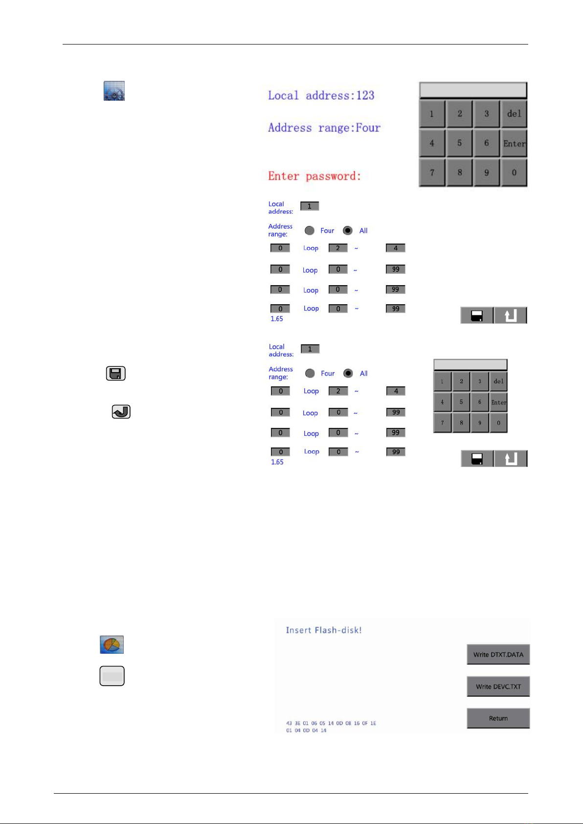
3.8 System Setup
Clicking “ ” icon enters password
input menu as shown in Fig. 6.
It shows the current address of fire
repeater, the current address ranges.
There are two methods to display ranges,
four range and general display.
Inputting the password of “7, 8, 9” and
then pressing “enter” key can enter setup
menu to modify the current configuration
as shown in Fig. 7
Clicking the grey editable box, the
system will prompt up a dialogue box
with a keypad as shown in Fig. 8.
Inputting the new data instead of the
previous one, pressing “Enter” key can
edit revise the corresponding contents.
Clicking “”icon can save the
modified message.
Touching “ ” or operating nothing
within 50s can return to the cover menu.
It returns to main monitor screen after
50s if fire or fault occurred here.
Note:
⚫Addresses of fire repeaters can be programmed together with detectors and modules connected on
the system.
⚫When the display mode is general display, it will display any messages of points from the intelligent
fire alarm control panel.
⚫When the display mode is four ranges, a single range can only display one range of the same loop,
and the starting address should be smaller than the ending one.
⚫When the addresses are less than four range, both starting address and ending address of the other
ranges that are not used should be set to 255.
3.9 Data Update
Clicking“”icon enters password input
menu. Inputting password of “7, 8, 9”, then
clicking“”enters Data Update menu.
Under this menu, data on the intelligent fire
alarm control panel can be transmitted into this
fire repeater through a U drive, as shown in Fig.
9.
“Write DTXT.DAT” key is used to update messages such as installation position of devices and so on.
“Write DEVC.TXT” key is used to update messages such as types of devices and so on.