Version 21.02.2017 CI-VL2-MMI3G-xxx
Contents
1. Prior to installation
1.1. Delivery contents
1.2. Checking the compatibility of vehicle and accessories
1.3. Boxes and connectors
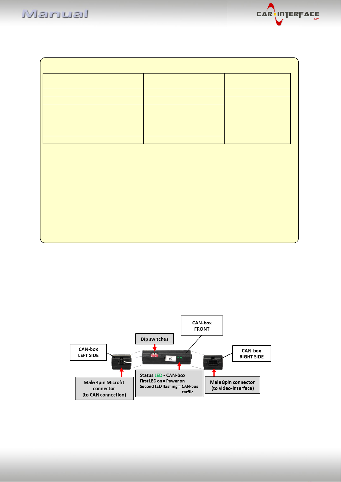
1.3.1. CAN-box
1.3.2. Video-Interface
1.3.2.1. Dip-switch settings
1.3.2.2. Enabling the interface’s video inputs (dip 1-3)
1.3.2.3. RGB-video input signal selection for after-market navigation (Dip 4)
1.3.2.4. Rear-view camera setting (dip 5)
1.3.2.5. Monitor selection (dip 7-8)
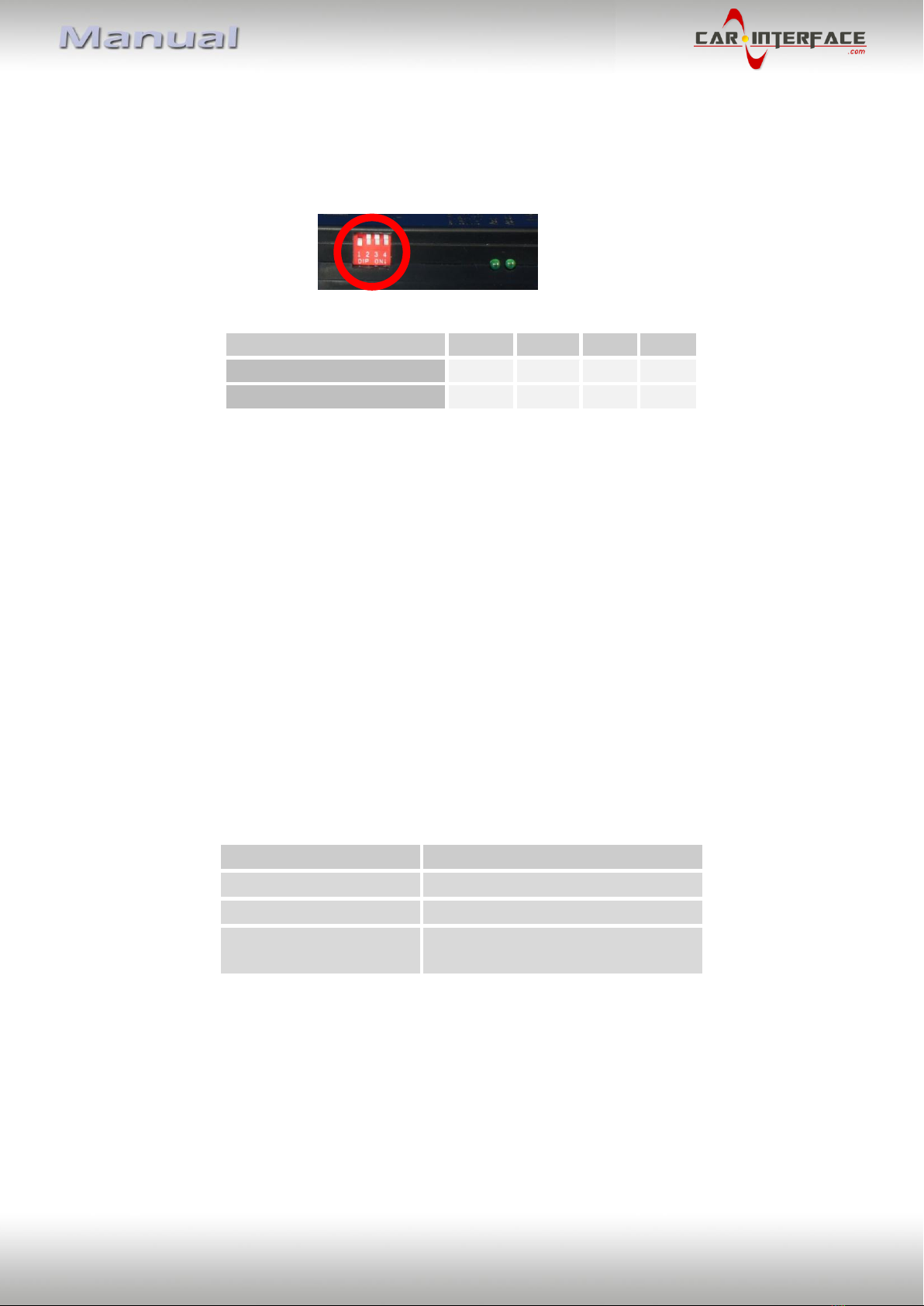
1.4. Dip-switch settings of CAN-box
2. Installation
2.1. Place of installation
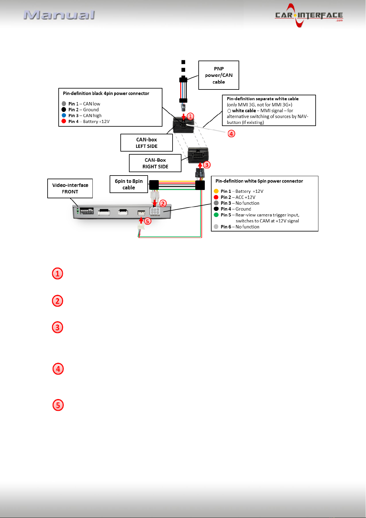
2.2. Connection schema
2.3. Connecting video-interface and CAN-box
2.4. Connecting power and CAN-bus
2.4.1. VL2-MMI3G-Q3 –Connection to the climate control panel and head-unit
2.4.2. VL2-MMI3G-GW –Connection to the CAN-gateway
2.4.3. RNS850 –Cable with open ends
2.5. Connection to the head-unit
2.6. Connecting peripheral devices
2.6.1. After market RBG navigation
2.6.2. Video-sources to AV1 and AV2
2.6.3. Audio-switch and audio-insertion
2.6.4. After-market rear-view camera
2.6.4.1. Case 1: CAN-box detects reverse gear
2.6.4.2. Case 2: CAN-box does not detect reverse gear
2.6.4.3. Video signal connection
2.7. Connecting video-interface and keypad
2.8. Picture settings and guide lines
3. Interface operation
3.1. By factory infotainment buttons
3.2. By keypad
4. Specifications
5. Frequently asked questions