VacuumChambers VP115 User manual

TRANSLATION OF THE ORIGINAL USER MANUAL
Manufacturer / distributor:
VacuumChambers.eu
drControl Dawid Roszczenko
Jodłowa 3A/34
16-001 Ignatki-Osiedle
Poland
E-mail: shop@vacuumchambers.eu; Telephone: +48535312207
2
All photos used in this manual are illustrative photos. The appearance and quantity of the elements supplied to the
customer and their mutual location may vary depending on the ordered vacuum set.
This user manual is based on current knowledge and experience. The manufacturer reserves the right to change the content
of this manual without informing the consumer.
ENVIRONMENTAL INFORMATION:
Do not dispose of that product as unsorted municipal waste.
Used equipment should be sent to an electro-waste collection point.
Nature friendly company.
SYMBOLS USED IN THE MANUAL:
Danger - A hazard that can cause injury or damage.
Hot surfaces. Risk of burns.
Read the user manual of the device.
Wear eye protection.
Wear protective gloves.
Wear protective clothing.

3
READ THIS USER MANUAL BEFORE USE. Keep the user manual for possible future use, as it may always be
necessary to remind the information contained therein, and it must be provided with the device in the case of
resale or user change.
WARNING! To avoid the risk of injuries and accidents, as well as to increase work efficiency and prevent
premature wear of the device, read all warnings, safety instructions and paragraphs marked with the symbol:
Contents
.................................................................................................................................. 4
................................................................................................................................................ 5
...................................................................................................................................... 5
........................................................................................................................... 5
.................................................................................................................................................... 6
A. Air manifold assembly. ..................................................................................................................................... 6
B. Preparation of the vacuum pump. ................................................................................................................... 8
C. Connection of elements of the vacuum set..................................................................................................... 8
................................................................................................................................................ 9
A. Fitting muffler. ...................................................................................................................................................... 9
B. Vacuum feedthrough with pouring hose and mechanical flow controller. ....................................................... 9
C. Stirrer mechanism. ............................................................................................................................................. 10
D. Vacuum trap. ...................................................................................................................................................... 12
E. Vacuum cold trap. .............................................................................................................................................. 12
.................................................................................................................................................... 15
...................................................................................................................................................... 16
............................................................................................................................................. 17
............................................................................................................................................................ 19
A. Tank gasket replacement. .............................................................................................................................. 19
B. Oil change. .......................................................................................................................................................... 19
.................................................................................................................................................................. 20
...................................................................................................................................... 21
A. EC declaration on conformity – rotary oil vacuum pumps. .............................................................................. 21
4
During work, use personal protective equipment, including eye protection,
protective gloves, clothing and footwear.
Never stand by or look directly into any vacuum chamber without proper
protective equipment, including eye protection and clothing.
The tempered glass lid is an inherently fragile material. As a result of a fall or
impact with sufficient force, the glass lid may break and crumble, causing splashes of its fragments. Therefore, always
wear protective clothing, in particular eye protection, during the operation and transport of the vacuum chamber or the
glass lid to prevent damage to the body and eyes. Moreover, you must not: allow mechanical damage to the glass (even a
slight scratching can cause a weak spot in the glass causing failure), allow it to fall from the work table, leave it in a place
where there is a risk of it falling or being hit by other objects.
Some parts of the vacuum pump get very hot during operation. To prevent burns, never touch the body
and the pump motor. Be careful when changing hot oil.
Implosion hazard. Failure to follow this user manual can result in property damage or serious injury.
The vacuum chamber is not a pressure chamber. Do not pump the vacuum chamber, or otherwise make
the pressure inside the tank higher than atmospheric pressure, as there is a risk of a tank explosion.
Perform servicing and maintenance of the vacuum set periodically.
Before each use of the vacuum set, it is necessary to check its technical condition, in particular the supply cable of the
vacuum pump, as well as the technical condition of the tank and lid.
The general rules for the use of equipment working under voltage must be observed.
Be sure to use the product in a safe, well-ventilated area, on a flat, stable surface.
Avoid excessive pollution of the working environment by dust, powders, small solids or water, as heavy contamination
can damage the pump.
The user must ensure that the chemicals used by him in the intended process or when cleaning the vacuum set do not
damage the elements of the vacuum set.
Pumps, available in the standard VacuumChmber.eu offer, are not intrinsically safe.
The customer is solely responsible for the appropriate selection of the vacuum set for the intended purposes and
technology.
Don not put any additional weight on the lid of the chamber. Do not set any vacuum pumps or other items that are not a
part of the vacuum system in the chamber.
The lid must be properly placed on the tank. It is not permissible for the gasket to extend beyond the outline of the lid at
any place. This situation can lead to a sudden unsealing of the chamber.
In the case of cracking, scratch or other lid damage immediately exclude it from use.
In the case of cracking, abrasion or other gasket damage immediately exclude it from use.
In the case of deformation or any other tank damage immediately exclude it from use.
Keep hard or heavy objects away from the vacuum chamber.
Do not apply additional forces on the chamber wall, for example by setting it on the grips, as this may cause deformation.
Do not move or transport chambers if they are under vacuum.
Do not assemble or disassemble individual parts of the vacuum set while the vacuum pump is operating or the vacuum
set is under vacuum.
Never put fingers or other objects inside the pump impeller cover. Keep your hair, clothing, gloves and other objects that
could get into the impeller away from moving parts.
Do not expose the device to rain or excessive moisture.
Do not leave the vacuum set unattended during operation.
Do not place live organisms in the vacuum chamber.
Do not subject any parts of the human body to under pressure.
Keep children, people with disabilities and animals away from the operating area of the device.
Be foreseeable, watch what you are doing, and be reasonable when using the device. Do not use the device when you are
tired or under the influence of drugs, alcohol or medication.

5
The device should be operated by trained technicians, mentally and physically able to operate the
vacuum set and its components.
Vacuum set is intended for professional use. It is not intended for non-professional use. The buyer is
obligated to secure the vacuum set and all its components against unauthorized use.
Do not use the device or any of its parts for purposes other than those for which it was intended. Do not make any
modifications or changes to the vacuum set or its components. Any modifications or changes are made by the customer
under his sole responsibility and will void the warranty.
Vacuum sets are used in the process of degassing casting materials such as silicone, resin, gypsum and the process of
impregnation of wood and other porous materials.
The vacuum chamber is a sealed tank. Inside it is possible to create a low-pressure environment by sucking out gases
contained therein by the vacuum pump.
The vacuum set is operated in the following conditions: ambient temperature between +5°C and +40°C, air humidity up to
80% at 20°C.
Photo 1: Vacuum set.
The vacuum set (Photo 1) consists of a vacuum chamber (2) and a vacuum pump (3) connected by a pneumatic hose (1). The
properties of the Vacuum Chamber are described in the next section of this manual. The vacuum pump included in the standard
vacuum set is a rotary oil pump. In the vacuum set, instead of a rotary oil pump, an oil-free piston pump or a diaphragm pump
can be used. This manual describes the installation of a vacuum set which includes an oil rotary pump. In case of using a
different type of pump or a pump supplied by another manufacturer, read and follow the instructions provided with the pump.
VcuumChambers.eu is not responsible for vacuum pumps provided by other manufacturers or distributors. The vacuum hose
included in the set is a reinforced pneumatic hose with a fitting enabling connection to a vacuum pump. The vacuum set is also
equipped with the oil necessary to start the pump for the first time (when using a rotary oil pump) and the user manual.
The vacuum set can be equipped with additional elements: a fitting muffler, a stirrer mechanism, a vacuum trap or a
vacuum feedthrough with a pouring hose and mechanical flow controller. These elements are described in chapter "5.
Additional equipment. " of this manual.
The vacuum chambers used in vacuum sets vary in size and material. Photo 2 shows an example of a vacuum chamber. The
vacuum chamber tank, depending on its type is made of aluminium, powder-coated steel or stainless steel. The lid of the
chamber is made of thick polycarbonate or tempered glass. The tank is provided with a silicone gasket which is durable and has
a low susceptibility to mechanical deformation. Excellent transparency of the lid allows observation of the degassing process.
1
2
3
6
The two ball valves allow for adjusting the degassing process, and the mounted vacuum gauge indicates the current vacuum in
the chamber. The chamber is equipped with an inlet air filter, which effectively prevents dirt from getting into a degassing
material. The chamber is attached to the pump with a barb, on which is fitted a reinforced hose with an internal diameter of 8
mm and a length of 1.5 m. The whole product is made from materials of the highest quality and a branded thread sealant.
Photo 2: Vacuum chamber.
Elements 1 to 5 together with pneumatic fittings form an air manifold. It also includes the washer and nut needed for its
assembly. The manifold is mounted on a tank or lid, but due to the risk of damage during transport, it can be attached to the
vacuum set separately. In that case, the customer should mount the manifold on the tank or lid by following the instructions in
this manual.
A. Air manifold assembly.
Photo 3: Air manifold.
If the air manifold (Photo 3) is supplied separately, unpack it and take off the nut and washer. Do not remove the O-ring.
The pneumatic fitting, from which the nut and the washer were removed, should be placed in the hole, prepared by the
1
2
nut
washer
O-ring
air manifold
3
4
5
7
8
6
1.
V
acuum gauge.
2. Barb fitting for 8mm hose.
3. Exhaust air valve.
4. Silicone gasket.
5. Lid.
6. Tank.
7. Air filter.
8. Intake air valve.

7
manufacturer. Depending on the model of the vacuum chamber, the hole is located in the wall of the tank or the lid of the
vacuum chamber. The manifold should be located on the outside of the chamber (Photo 4) or on the top of the lid (Photo 2).
Photo 4: Air manifold inserted into the hole.
The washer and nut should be placed on the manifold fitting on the internal side of the tank or bottom side of the lid.
Smooth washer edges should touch the tank wall (or lid wall). Use one spanner to tighten the connection and the other spanner
(or your hand) to hold the fitting. Tighten the nut until you feel resistance. It is important to place the O-ring and the nut
concentric. Incorrect positioning may result in a lack of tightness in the chamber. Photo 5 shows the incorrect position of the
sealing ring. Do not tighten the O-ring too hard or you will deform it and damage its properties.
Photo 5: Incorrect position of the O-ring.
Photo 6: Air manifold correctly installed.
Photo 6 shows a correctly mounted air manifold on the tank wall. The green stopper plug, visible in the photo, is used to
protect the vacuum gauge against spilling glycerine during transport or assembly. It should be removed after all components of
the vacuum set have been assembled. Leaving the stopper plug in the vacuum gauge may result in incorrect pressure
indications.
O-ring washer and nut
8
B. Preparation of the vacuum pump.
1) Before the first use necessarily fill the vacuum pump (Photo 7) with the oil provided with the set. To do that, place the
pump on the flat, horizontal surface, unscrew the red plug (1) and pour the oil through the oil feed hole. For some models of
pumps (when there is no red cap), the oil should be poured through the hole in the pump housing, after the blue oil filter
cylinder (2) has been unscrewed. Oil pour gradually, at the same time control the oil level by observing the oil sight glass (4).
Photo 7: Elements of the vacuum pump and correct oil level.
The pump delivered to the client is never filled with oil. A little amount of oil in the oil sight glass indicates only
the fact that the pump was tested before the shipment. The pump must necessarily be filled with oil before
use.
2) Remove the plug (3), protecting the air filter, placed on the exhaust of the vacuum pump. Not applicable to the VP1RS-
0.5 model.
C. Connection of elements of the vacuum set.
1) Screw the connector, tighten the pneumatic hose, to the vertical fitting on the vacuum pump. Screw the connector
gently, using a spanner, until the resistance is felt.
Photo 8: Pneumatic hose mounted on the barb of the ball valve, secured with worm drive hose clamp.
2) Put the spare end of the pneumatic hose on the barb of the chamber ball valve. Secure this connection using a worm
drive hose clamp.
3) Remove the green plug of the rubber plug on the vacuum gauge.
It is recommended to connect the vacuum set only with parts and products supplied by VacuumChambers.eu.
If the customer connects the vacuum set or its parts with elements or devices from other manufacturers, the
customer is solely responsible for the appropriate selection of these elements, their compatibility and the
quality of their connection. The manufacturer is not responsible for any damage or losses caused by incorrect
selection, matching, use or combination of the products. The above principles apply in particular to vacuum pumps purchased
from other suppliers.

9
Depending on the selected model or on the customer's order, the vacuum set can be equipped with: a fitting muffler, stirrer
mechanism, vacuum trap or vacuum feedthrough with a pouring hose and mechanical flow controller.
A. Fitting muffler.
Photo 9: Fitting muffler and air manifold with a mounted muffler.
The fitting muffler (Photo 9) disperses the air stream entering into the chamber, while balancing the vacuum. It prevents
casting materials from spilling inside the chamber. This accessory should be screwed manually (not using any tools) onto the
mounted air manifold on the internal side of the tank or the bottom side of the lid. The diffuser is not included as a standard
accessory with every vacuum set.
B. Vacuum feedthrough with pouring hose and mechanical flow controller.
The feedthrough integrated with the vacuum chamber (Photo 10) enables to supply of casting materials from the external
container directly into the interior of the chamber under vacuum. The mechanical flow controller (4), included in the set, allows
for precise process control. To regulate the process of collecting material into the chamber, operate the wingnut located on the
regulator. It allows for reduce or block pouring hose capacity.
When using the vacuum set, the pouring hose becomes dirty with the supplied materials. This situation is normal
operational wear and is not covered by warranty. The customer is obliged to replace a dirty hose each time, following the
instructions below.
To remove the hose from the vacuum feedthrough (1), loosen the nut (2) with a spanner. The hose should be at ease
removed from the feedthrough. The next step is to remove the flow regulator (4) from the hose after loosening the wing head
screw.
Put the mechanical flow regulator (Photo 11) on the new hose. The hose should be centrally located under the regulator
stamp, between the stamp and the opposite wall. Tighten the regulator with the wing head screw as needed.
Photo 10: Vacuum feedthrough with pouring hose and flow controller mounted on the tank.
1
2
3
4
10
Photo 11: Mechanical flow controller.
The spare end of the hose should be placed in the vacuum feedthrough (Photo 10). A sufficiently long section of the hose
should be inside the tank. Use one spanner to tighten the feedthrough nut and another spanner to hold the feedthrough.
C. Stirrer mechanism.
The stirrer mechanism is an additional accessory of the vacuum chamber. It facilitates and speeds up the degassing process.
The stirrer mechanism can only be installed in the chamber suitable for this. During operation, the stirrer must not move faster
than 300 rpm. Photo 12 shows the chamber lid (1) with the agitator (4) attached to it.
Photo 12: Agitator mounted on the lid.
The agitator is ended with an ISO metric screw thread (M14), which allows it to be screwed into the coupling (3). This
connection is secured with a lock nut. The coupling has a hole on the upper side of the lid to which the agitator drive can be
connected. The hole also has an M14 thread. A bolt with a nut may be inserted therein. The lid of the vacuum chamber with the
stirrer mechanism additionally has two polycarbonate windows (2), which enable the observation of the degassing process. They
are secured during transport with a protective foil.
The chamber adapted to the installation of the stirrer mechanism (Photo 13) has a metal lid (1) and additional elements.
Those are:
stamp
1
2
3
4

11
Photo 13: Vacuum chamber with stirrer mechanism.
The legs (3) and the castors (4) makes possible to move the chamber and to place a container under the tank. The clamps
(2) are used to close the chamber. The drain valve (5) allows the chamber to be drained.
The lid should be mounted centrally in the middle of the chamber (Photo 14). The lid should be secured with clamps. Make
sure that the elements of the clamps of the lid are located directly above the corresponding elements of the clamps on the
chamber. Additionally, it is important that the label "THIS SIDE TO VACUUM GAUGE" is placed next to the vacuum gauge.
Photo 14: Correct location of the lid on the chamber.
If it is difficult or impossible to close at least one clamp, make sure that the lid is correctly positioned. If necessary, the
length of the clamps can be adjusted.
To avoid damage to the chamber during transport, the castors usually are included separately. The manufacturer attaches
to the package a set of bolts, washers and nuts that allow the customer to assemble the castors by himself. Their correct
installation is shown in the picture below.
1
3
4
5
2
1.
Lid.
2. Clamps.
3. Legs.
4. Castors with brake.
5. Stainless steel drain valve 1 ¼ inches.
12
Picture 1: Correct installation of the castor to the tank leg.
D. Vacuum trap.
The vacuum trap (Photo 15) is a vacuum chamber with a modified configuration. It is used in the infusion process as a
protection for a vacuum pump.
Photo 15: Vacuum trap.
Two ball valves (1,2) and a glycerine vacuum gauge (3) are mounted on the lid of the vacuum trap. The valves enable control
of the process and are suitable for connecting pneumatic hoses. The vacuum gauge indicates the current pressure in the tank.
The separate use of valves and vacuum gauge instead of the air manifold (used in standard chambers) makes easier vacuum trap
cleaning.
After getting inside the trap, the liquid casting material falls to the bottom by gravity. This prevents material from getting
inside the vacuum pump. It protects against contamination of the trap elements and the pneumatic hose leading to the pump.
During proper use, the resin only comes into contact with the hose leading to the mould and the ball valve of the trap lid
connected to it. To simplify cleaning of the vacuum trap, it is recommended to place a container inside the tank to hold excess
resin that gets inside the trap.
E. Vacuum cold trap.
A vacuum cold trap is a type of vacuum chamber. It is used to protect the vacuum pump against harmful compounds that
may evaporate in the vacuum chamber. Such compounds can be, for example, water or ethanol. Due to the low pressure inside
the vacuum chamber, water and ethanol can evaporate at room temperature. Vapours can cause oil turbidity, deterioration of
pump performance, corrosion and damage to individual elements of the vacuum pump. The vacuum cold trap is used as an air
purifier for the air passing from the vacuum chamber to the pump. In the vacuum cold trap, the vapours undergo a process of
deposition (the transition from gas phase to solid phase). The cold trap is not a filter and does not protect the pump against all
harmful factors, e.g. dust. It is used only to ensure appropriate conditions for the deposition process.
1
3
1.
Ball valve.
2. Ball valve.
3. Vacuum gauge.
2

13
Photo 16: Vacuum cold trap.
The vacuum cold trap (Photo 16) consists of two tanks - the outer tank (5), where the deposition process takes place, and
the inner tank, in which the cooling agent (e.g. dry ice) is placed. The outer tank is equipped with the vacuum pump connecting
valve (1) and the vacuum chamber connecting valve (6). The vacuum pump connecting valve is equipped with an unsealing valve
(2) with an air filter. The inner tank has a polycarbonate lid. The wide flange of the inner tank (4) is also a cover for the outer
tank. The tightness of the vacuum cold trap is ensured by a blue silicone gasket put on the outer tank. Photo 17 shows the inner
tank, outer tank, blue silicone gasket and ice formed as a result of deposition.
Photo 17: Inner tank, outer tank, silicone gasket and ice formed on the internal tank.
The inner tank lid limits the contact of the cooling agent with the environment. This slows down the cooling agent heating-
up speed, and thus prolong its useful life. However, it is not possible to completely prevent the heating of the cooling agent
during its use. Gases are released from the cooling agent as a result of heating. Allow these gases to escape from the inner tank,
as their accumulation may result in a dangerous pressure build-up in the inner tank. Therefore, the inner tank lid must not be
loaded with other objects, nor have a limited free lift. The cooling agent should be placed only in the cold trap internal tank
(Photo 18). After placing the cooling agent inside the cold trap, cover the inner tank with the lid.
inner tank
ice formed in the
deposition process
outer
tank
silicone
gasket
1
2
1.
Vacuum p
ump connecting valve
.
2. Unsealing valve.
3. Inner tank lid with a gasket.
4. Inner tank flange.
5. Outer tank.
6. Vacuum chamber connecting valve.
3
4
5
6
outer tank
14
Photo 18: Vacuum cold trap with dry ice inside.
The deposition takes place inside the outer tank. The outer tank receives air sucked from the vacuum chamber. Air rapidly
cools down as a result of contact with a very cold inner tank wall. This causes vapour deposition on the inner tank walls. Photo
17 shows the ice formed in the deposition process. The purified air from the cold trap goes then to the vacuum pump.
Photo 19 shows the result of the cold trap work. Vacuum pumps visible in this photo were used for water degassing in the
vacuum chamber. The pump on the left was working in a vacuum set with a vacuum cold trap between the chamber and the
pump. As a result, the air was cleaned of water vapour and prevented the vacuum pump from contaminating with water. The oil
remained clear. In the pump, shown on the right side of the photo, no cold trap was used. The vacuum pump was contaminated
with water and the oil became damp and turbid.
Photo 19: The result of the cold trap work - oil in vacuum pumps clarity (left: clear oil when using a cold trap, right: turbid oil
when no cold trap is used).
To use the vacuum cold trap:
1) Connect the cold trap to the vacuum chamber (connect one end of the pneumatic hose to the vacuum chamber connecting
valve and the other end to the vacuum chamber exhaust air valve).
2) Connect the cold trap to the vacuum pump (connect one end of the pneumatic hose to the vacuum pump connecting valve,
and the other end to the vacuum pump).
3) Place the inner tank centrally in the outer tank. The outer tank blue gasket should not protrude beyond the inner tank
flange.
4) Open the inner tank by removing the inner tank lid.
5) Fill the inner chamber with a cooling agent (e.g. dry ice):
a. Read cooling agent safety instructions and follow the information contained therein.
b. Put on cold resistant gloves.
c. Put the cooling agent into the cold trap inner tank.
d. Close the inner tank with the lid (without pressing the lid down).
6) Open the pump connecting valve and chamber connecting valve (place the valves handles parallel to the valves).
clear oil visible in
the sight glass
turbid oil visible in
the sight glass

15
7) Close the unsealing valve (place the valve handle perpendicular to the valve).
8) Start degassing the chamber according to point 7. “Operating manual.” of this manual.
9) Control the amount of material accumulating in the cold trap.
10) If a large amount of material has accumulated inside the cold trap:
a. Close the cold trap valves: vacuum pump connecting valve and vacuum chamber connecting valve (place the valve
handles perpendicular to the valves).
b. Turn off the vacuum pump.
c. Open the unsealing valve (place the valve handle parallel to the valve). Allow the pressure inside the cold trap to
equilibrate with the ambient pressure.
d. Take out the inner tank using cold resistant gloves.
e. Remove any excess deposition material.
ATTENTION! The deposition material should be removed very carefully due to its very low temperature.
f. Place cleaned inner tank back into the outer tank.
g. Close the unsealing valve.
h. Open the vacuum pump connecting valve (place the valve handle parallel to the valve).
i. Start the vacuum pump. Lower the pressure inside the cold trap.
j. Open the vacuum chamber connecting valve (place the valve handle parallel to the valve).
k. Continue the degassing process.
l.
Clean the vacuum cold trap again if necessary (go back to point 10) a.).
11) When the degassing process is complete, close the vacuum chamber connecting valve and the vacuum pump connecting
valve (place the valves handles perpendicular to the valves).
12) Disconnect the vacuum pump and the vacuum chamber from the cold trap if needed.
13) Open the unsealing valve (place the valve handle parallel to the valve). Allow the pressure in the cold trap to equilibrate
with the ambient pressure.
14) Handle the remaining cooling agent following its safety instructions.
15) Clean the cold trap.
Be very careful when operating the cold trap. Especially when cleaning the cold trap from cold deposition
material.
The vacuum cold trap is very cold when the cooling agent is inside. Risk of frostbite in case of direct
contact with cold trap elements.
Use cold resistant gloves.
Do not touch the device if not necessary.
Always follow all cooling agent instructions and warnings.
The inner tank lid must not be pressed down by other objects nor have limited free lift.
A large amount of accumulated deposition material can block the airflow from the vacuum chamber to the vacuum pump. If
that happens, clean the vacuum cold trap according to point 10) of the instruction above.
Accumulated material, when reaches the ambient temperature and pressure, most often turns into liquid (e.g. water,
ethanol). When this happens, cleaning the cold trap is easier. Be very careful when cleaning cold trap before material turns into
liquid. The material is then very cold and there is a high risk of frostbite.
1) Place degassing material in the additional container into the chamber.
2) Place the lid on the chamber. Make sure it’s placed centrally on the tank - exactly as shown in photo 20 on the left.
The chamber must not be used if the lid is shifted to the side, as shown in photo 20 on the right. If the lid is in the wrong
position, it is necessary to correct lid position before starting to use the chamber.
For a metal lid with clamps (chamber with a stirrer mechanism), place the lid on the tank following paragraph "4C. Stirrer
mechanism.” of this manual.
3) Close the inlet air valve (set valve handle perpendicular to the valve).
4) Close the exhaust air valve (set valve handle parallel to the valve).
5) Turn on the vacuum pump.
6) In the first phase of the suction it may be necessary to press the lid down to the tank until the increasing vacuum in the
chamber is noticed.
16
7) During degassing, casting products significantly increase their volume, note that opening the inlet air valve prevents the
degassing products from spilling out when a too small container is used. The operator should control the process and react
according to the increase in volume of the product. So that the product does not get into the lid of the chamber and
contaminate the connections there.
8) Degassing should continue until the degassing material stops increasing its volume and rapidly drops and reduces its
volume. The material will have a homogeneous, clear appearance.
9) Before turning off the pump, close the exhaust air valve.
10) Turn off the vacuum pump.
11) Slowly open the inlet air valve to balance pressure inside a chamber. After this step, the lid can be removed.
12) The process above can be repeated for the filled forms to obtain the best results.
Photo 20: Correct (left) and incorrect (right) positioning of the lid on the chamber.
Proper work of the vacuum chamber can only be guaranteed by using a vacuum pump which allows achieving a vacuum of
at least 0.1mbar (10Pa). It is recommended to use vacuum pumps tested and recommended by VacuumChambers.eu.
Before starting work, make sure that the oil level in the pump is suitable. The pump can’t work without oil (possible pump
seizure) or with its excessive amount (possible oil splashing at the pump outlet).
In case of using the vacuum pumps without the protection against oil return (such as a one-way solenoid valve or
mechanical valve), disconnect the pump from the chamber after reaching the required vacuum. Remember to close the
exhaust air valve first. All VacuumChambers.eu pumps are equipped with a one-way valve.
When operating vacuum pumps that do not come from the VacuumChambers.eu offer, please refer to the operating
instructions supplied with the pump by the manufacturer.
Casting products placed in the chamber should be placed in an additional container that is large enough to avoid the spillage
inside of the chamber.
The vacuum gauge with removed green stopper plug shouldn’t be rotated downwards as it can cause glycerine leaking.
The chamber lid should only be taken off after the pressure in the chamber is equilibrated with the atmospheric pressure. In
the case of a very strong lid suction, waggle the lid from side to side, while gently holding the gasket with the other hand.
Raising the lid quickly can cause ripping off the gasket. Especially in the case of new silicone gaskets, there may be an

17
occurrence of its strong adherence to the lid. It is recommended to protect the new gasket surface, for example by technical
talc.
Chambers with polycarbonate lids are not designed for wood stabilization or to work with alcohol, ethanol, acetone and
monomers or polymers based on acrylic.
When using a vacuum chamber for degassing aggressive resins, an additional filter should be placed between the chamber
and the pump if degassing takes more than 10 minutes. Not using a filter can lead to pump damage, which is not subject to
future warranty.
The vacuum pump must always be set below the vacuum tank.
The time of continuous operation of the vacuum pump should not exceed 15 minutes with the connected load, such as a
tank or installation.
Time of continuous operation of the vacuum pump must not exceed 30 minutes in conditions of free air circulation, without
connected load.
Do not allow the vacuum pump to overheat. Exceeding the temperature of 75°C on the motor housing significantly shortens
the life of the pump, and in some cases can lead to its complete damage.
RS series of rotary, oil sealed vacuum pumps are not designed for continuous operation. The recommended mode of use is
intermittent work S3 25%.
Oil change in the vacuum pump should be carried out every 20 work hours. One of the symptoms of the necessity to replace
oil is not reaching the maximum vacuum. Turbid or dark colour oil should be replaced with a new one.
In the case of using a vacuum set for processes that cause strong contamination of the oil, for example wood stabilization, it
is recommended to drain the oil after each process. The drained oil can be re-used as long as it has returned to its original
properties. Not following this point may cause corrosion and accelerated wear of pump mechanisms.
Under certain conditions, the rotary oil vacuum pump may have trouble starting. This happens especially at low
temperatures which cause the oil to thicken. It is also related to the vane positioning when the pump is switched off. This is
due to the operating principle of the pump and is not a defect. In case of problems with starting the pump, the air inlet of
the pump must be unsealed, which should enable the pump to start.
It is recommended to store the rotary oil vacuum pump at room temperature. If the pump is stored at lower temperatures,
it is recommended that the pump be moved to a warm space before it is put into operation, which will enable to warm the
cold oil to room temperature. This prevents possible problems with starting the pump.
Possible and the most common failures and problems are described below, as well as recommended procedures in case of
their occurrence.
Problem
Possible cause
Recommended procedure
The vacuum
pump does not
start.
No connection to the power
supply.
Check connection to
the
power supply.
The pump
is overheated.
Allow the pump to cool down, then try turning it
on again.
Low temper
ature storage of
the pump causing the oil to
thicken.
Leave the pump at room temperature and wait for the pump
and oil to warm up. Try to start the pump again. Do not store
the pump in cold temperatures.
Movement of oil from the
pump to the vacuum
chamber.
A pump
without protection
against oil return was used.
Replace the used pump with new pomp
which has
a non
-
return valve (all pumps available in the VcuumChambers.eu
offer are equipped with a non-return valve).
The pump heats up
to a
temperature exceeding
65
°C.
Thermal sensor failure.
S3 25% intermittent operation
was not used.
Stop using the pump. Contact the supplier for additional
information or to perform a warranty or post-warranty
repair.
Loud, unusual vacuum pump
operation.
Pump damaged.
Stop using the pump. Contact the supplier to assess possible
damage, obtain additional information, or perform a
warranty or post-warranty repair.
The glycerin vacuum gauge
at atmospheric pressure
does not show a value of
“0".
Clo
sed green plug
on the
vacuum gauge.
Pull back the green plug of the vacuum gauge or remove it
completely to allow the pressure in the vacuum gauge to
equilibrate with the atmospheric pressure.
Failure to achieve the values
of the negative pressure in
the
vacuum chamber
declared by the
Vacuum pump oil level too
low. Poor oil quality (oil is
contaminated or unsuitable
for vacuum pumps).
Check the quantity and quality of the oil in the vacuum pump
according to point 10B. “Oil change.” of this manual. A
heavily contaminated pump may require several oil changes
18
manufacturer.
The pump
is worn or
damaged.
Contact the supplier for additional information or to perform
a warranty or post-warranty repair.
Weakening of
pump elements
by using harmful compounds
in the degassing process
Stop using the pump. Contact the supplier for additional
information or to perform a warranty or post-warranty
repair.
Leakage on one or more
components of the vacuum
set.
Check
in order a
s below
:
Closing of the proper valves (see: 7. “Operating
manual.”).
Tightness of the connection of the pneumatic hose with
the chamber and the pump. make sure that a worm
clamp is used in the place where the hose and the
vacuum chamber are connected.
The elements connected by the user (especially if it is the
first start-up), including the tightness of the connection
between the air manifold and the chamber.
All other elements of the vacuum set and the vacuum
chamber (Each vacuum chamber delivered to the
customer undergoes leak tests, therefore the risk of
leakage directly in the chamber or air manifold is low.)
After the pump is turned off,
pressure begins to rise
slowly in the chamber.
The open
valve between
the
vacuum chamber and
pneumatic hose.
Vacuum
should be performed again. Before turning off the
pump, close the valve between the vacuum chamber and the
pneumatic hose.
Sli
ght leakage on one or more
elements of the vacuum set.
Check the vacuum set for leaks according to: " Leakage on
one or more components of the vacuum set.” in the line:
"Failure to achieve the values of the negative pressure in the
vacuum chamber declared by the manufacturer.".
The lid cannot be opened.
The lid is difficult to remove.
There is a negative pressure in
the tank.
Open the
inlet
air valve and wait for the pressure in the tank
to equilibrate with the ambient pressure. Try to remove the
lid again.
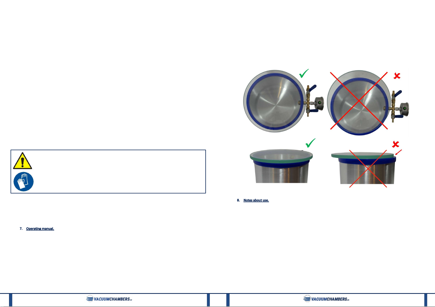
The lid sticks to the gasket.
The silicone gasket is removed
together with the lid.
The gasket can be sprinkled with a s
mall amount of technical
talc, which should reduce gasket sticking to the lid.
The polycarbonate lid goes
milky or has small scratches
after cleaning.
Improper cleaning of the lid
(using unsuitable chemicals).
Replace the lid with a new one. Do not use
the substances
used so far. Clean the lid with a damp cloth.
If it is necessary to continue using the substances used to
clean the lid, the polycarbonate lid can be replaced with a
glass lid (but only if the glass lid is suitable for the intended
process and the substances to be used during cleaning).
Cracking of the
polycarbonate lid.
Use
in the chamber:
ImpResin90, alcohols,
ethanol, acetone, acrylic
monomers or polymers or
other substances harmful to
the lid.
Replace the lid with a new one.
Stop using
the listed
substances - the polycarbonate lid is not suitable for them. If
the customer intends to use the chamber with the listed
substances, the polycarbonate lid should be replaced with a
tempered glass lid (but only if it is suitable for the intended
process).
Mechanical damage or
weakness to the vacuum set
or its components. In
particular: silicone gasket, lid
or vacuum pump.
Incorrect operatio
n of the
vacuum set or its elements.
S
top using damaged elem
ents. Contact the supplier to
replace damaged elements with new ones, if possible. Inform
the supplier about how the vacuum set or its elements have
been damaged for additional information and guidance that
may reduce the risk of similar damage in the future.
Chemical damage or
weakne
ss of the vacuum set
or its elem
ents. In particular:
a lid or a vacuum pump.
Use of unsuitable materials
when using or cleaning the
vacuum set or its elements.
Stop using damaged elem
ents. Verify the safety of the
substances used in the process and clean the vacuum set or
its elements. Contact the supplier to replace the damaged
elements with new ones or more suitable for the intended
process, and to obtain additional information.
If the above information did not allow to fix the problem or the problem that occurred is not described above, please
contact the supplier for additional information or to return the product for warranty repair or post-warranty service.
In the case of special vacuum sets or the use of additional equipment listed in this manual, if the problem with the vacuum
set or its element is not described above, contact the supplier for additional information, replacement of defective elements or
warranty or post-warranty repair.

19
The vacuum chamber must be kept clean and the pneumatic components must be taken care of so that the extraneous
objects don’t get into them and as a result block and damage the chamber.
The chamber tank can be cleaned with water and a light detergent like the liquid dishwashing detergent. The polycarbonate
lid of the chamber should be cleaned only by using a soft cloth moistened with warm water. Detergents may cause
polycarbonate lid to become milky or scratched. Glass lid may be cleaned with any detergents unless they cause it to be
scratched. Do not clean the vacuum system with flammable liquids, solvents or by spraying it with a stream of water.
A. Tank gasket replacement.
The silicone gasket on the tank is a consumable item and its wearing out is a natural process. Excessive use of the gasket or
its damage may cause leakage of the chamber. If there are visible signs of wear, damage, dirt or leakage of the chamber, gasket
must be replaced. The gasket may lose its elasticity or harden as a result of contact with the materials used by the customer. In
that case, it should be replaced.
For replacement, the old gasket must be removed. Take it with hand and pull it off the tank wall. The gasket should be
completely removed, and no contamination should be left in the place of its installation.
Picture 2: Gasket - sectional view.
The new gasket should be placed on the tank in place of the old one. Installation should begin by positioning a short section
of the gasket on the edge of the tank. It is necessary to open the gasket gap locally (Picture 2) so that it can be easily placed on
the wall. When the first section of the gasket is on the tank edge, hold it with hand and slide the rest of the gasket on. The
application should continue along the gasket. Finally, press the gasket with a hand down to the tank along its entire length. Do
not apply too much pressure or hit the gasket with hard objects. Hitting the gasket can damage it, which can cause leakage in
the vacuum set.
B. Oil change.
This section is for changing the oil in the rotary oil vacuum pump available in VacuumChambers.eu offer. In case of using
another vacuum pump, follow the pump supplier’s operating instructions.
Oil in rotary vacuum pumps should be changed every 20 operating hours and at least once a year. Also, failure to reach the
maximum vacuum value, oil turbidity or a change in its colour to dark is an indication of the need to change the oil. Used oil
must be completely drained from the pump and replaced with new oil.
Oil change should only be performed when the pump is warm. Be especially careful when working with hot oil. Before
changing the oil, prepare a sufficiently large container for the old oil and a sufficient quantity of the new oil. The oil capacity of
rotary vacuum pumps ranges from 180 to 600 ml depending on the model. To change the oil:
1) Place the pump on a flat, level surface.
2) Place the old oil container below the vacuum pump so that the pump oil can drain freely into it.
Place the old oil container below the vacuum pump, below the oil drain (the drain is located under the visor and is closed
with a hexagonal socket head screw), in such a way that the oil flows freely into the container.
3) Unscrew and remove the entire oil mist filter (blue cylindrical part) or the red oil filler cap.
4) Open the oil drain.
Unscrew the oil drain screw carefully with an Allen key. Be careful not to lose the O-ring, which is located on the screw
being unscrewed.
gasket gap
20
5) Allow the oil to drain freely into the container.
To remove oil thoroughly from the pump, the pump can be started for a few seconds while the oil is being drained. When
doing this, the pump's air inlet should be open, at the same time the air outlet should be partially covered with a cloth. Do
not run the pump as described for more than 20 seconds.
6) When the oil stops draining, the pump can be gently tilted with the oil drain downwards to facilitate drainage of the old oil
into the container.
7) After draining the old oil, secure the oil drain
The drain securing screw with the O-ring on should be screwed back in the oil drain and tightened. The screw must not be
tightened too much to avoid O-ring damage. The entire O-ring should be seated completely in the recess of the pump's
aluminium housing. O-ring protruding outside the housing causes oil leakage.
8) Fill the pump with new oil following point 5. B. “Preparation of the vacuum pump.” of this manual.
9) Make sure the oil drain is tightly closed.
Oil drainage screw may leak out if it is tightened too little. In that case, gently tighten the screw and make sure that the O-
ring is positioned correctly. Tightening the screw too much can damage the O-ring.
Dispose of used oil in accordance with local regulations.
VacuumChambers.eu guarantees that the vacuum set will be operational and free of defects for 12 months from the date of
purchase. In the case of a breakdown during this period, VacuumChambers.eu will repair or replace any damaged system
element on the terms described in the warranty card included in the set.
This limited warranty does not cover damage to the system caused by improper use, maintenance or use not following this
manual. Any use of the device which not follow the intended purpose given above is forbidden and will void the warranty and
the manufacturer's liability for any damage resulting therefrom. Any modifications of the device made by the user release the
manufacturer from liability for damage and harm caused to the user and the environment. Proper use of the device also applies
to maintenance, storage, transport and repair.
VacuumChambers.eu is not liable for damages, nor does it cover them under the warranty, for any kind of losses resulting
from the breakdown of this product. In the case of a claim, VacuumChambers.eu's sole responsibility is to accept a return or
exchange of the product itself.

21
A. EC declaration on conformity – rotary oil vacuum pumps.
This manual suits for next models
14
Table of contents
Other VacuumChambers Vacuum Cleaner manuals
Popular Vacuum Cleaner manuals by other brands

Silvercrest
Silvercrest SFR 3.7 D3 Assembly, operating and safety instructions

Superabrasive
Superabrasive LAVINA V25E user manual

Shark
Shark Rotator NV340UK Slim-Light Lift-Away owner's guide

Philips
Philips EasyStar FC8802 user manual

Silvercrest
Silvercrest SMS 300 A1 Operating instructions and safety instructions

Melissa
Melissa 640-070 instruction manual