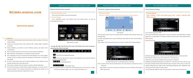
VAG-Navisystems NaviTouch User manual

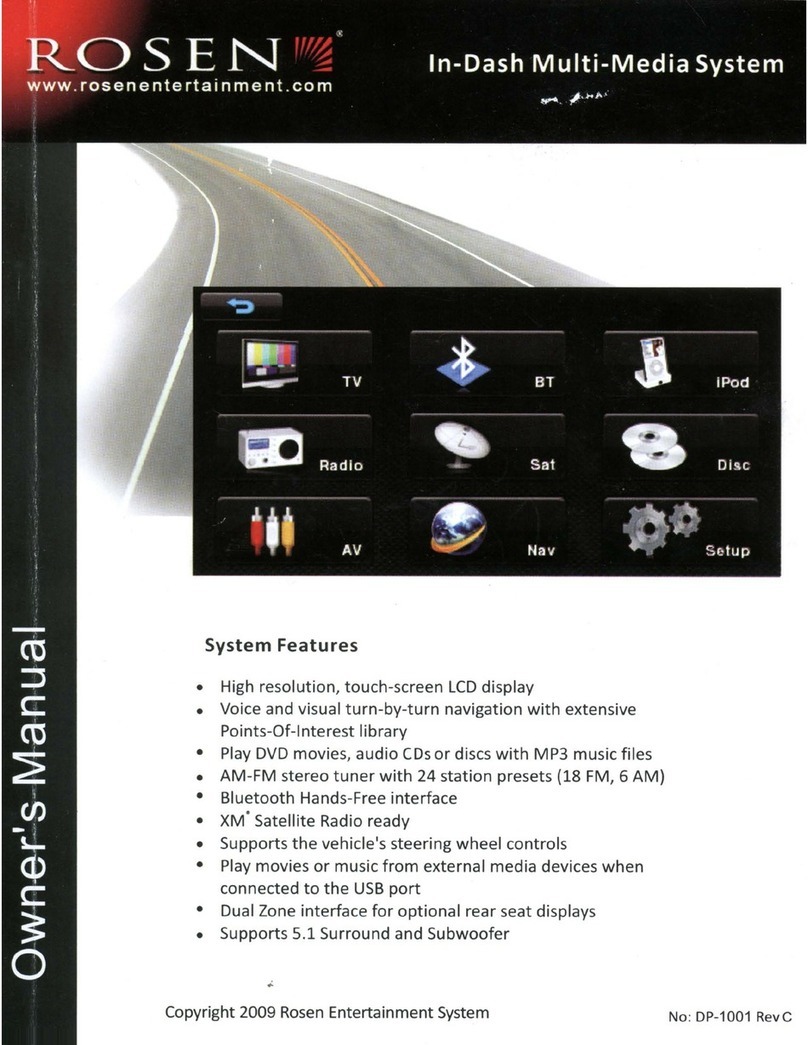
NaviTouch® system for
Audi A6 & Q7 with MMi 2G High
installaon manual

Index
1. Component idencaon – Pág.3
1.1. Mulmedia interface components– Pág.3
1.2. GPS Box components– Pág.4
1.3. Voice module components – Pág.4
2. Installaon – Pág.6
2.1. Mulmedia interface installaon diagram – Pág.6
2.2. Seng up the mulmedia interface before installing it – Pág.7
2.3. Mulmedia interface installaon and connecons – Pág.8
2.4. POWER connector cables and connecons – Pág.13
2.5. Aermarket rear view camera connecon – Pág.14
2.6. GPS Box installaon and connecons – Pág.15
2.7. Voice module installaon and connecons – Pág.17
2.8. Linking up the GPS Box and the mulmedia interface – Pág.18
3. GPS Box conguraon - - System conguraon – Pág.19
3.1. Calibrang touch and adjusng the image – Pág.19
3.2. RESET – Pág.21
3.3. Maps SD card and GPS signal – Pág.21
3.4. Checking the GPS signal – Pág.23
4. FAQ’s/Solving problems – Pág.24
2

1. Component idencaon
1.1 Mulmedia interface components
Mulmedia interface
AV cable Addional switch (oponal)
Touch IN cableIR cableLVDS cable
Touch OUT cable
Remote control IR sensor
Power cable
3

1.2 GPS Box components
1.3 Audio components
GPS Box
USB extensor
GPS-Box power
wiring harness
Touch panel
Hidden Microphone
(specic for overhead
courtesy lights panel)
Voice module
wiring harness
Voice module Voice module
audio conecon cable
GPS antenna
4

Basic knowledge before installaon:
•Please, read fully and carefully this installaon handbook before you aempt to install
the kit in your vehicle.
• Start the installaon once you have the car stopped and the key out of the ignion slot,
supply power must be the last step in installaon.
• When you connect the product and his accessories cables or connecons to the vehicle
components, the power cables of the products must be unplugged.
• Make sure that there are no electric or magnec devices near of the installaon place.
• Installaon must be performed by a qualied specialist.
• Product losses his warranty if you dismantle it or if you try to x it without the manu-
facturer permission. If you break up product security sckers, warranty will be lost too.
• Check that you have received all the product components before the installaon. If you
see any part damaged or faulty, contact us immediately.
• Problems made by a user mistake in the installaon or manipulaon of the product
suppose the warranty invalidaon.
• Vag-Navisystems S.L. WON’T make responsible if the product damages the car or user,
caused by a wrong installaon or an improper use of the product.
You must note the manufacturer regulaons for the manipulaon of
electric components, and the disconnecon of the airbags and the
dismantling procedures of interiors or pieces needed to perform the
installaon.
5
2. Installaon
2.1. Mulmedia interface installaon diagram
6

2.2. Seng up the mulmedia interface before installing it:
2.2.1 Mulmedia interface conguraon:
DIP switches:
Using the DIP Switches of the mulmedia interface you will be able to enable/disable the external mul-
media devices, Navigaon, DVD, rear cameras, etc… anything that you connect. For example, if you are going
to connect a mulmedia device in the AV1, and another in the AV2, we will just enable the corresponding
DIP Switches (DIP2 and DIP 3), if we do like this, we will only have that 2 enabled sources in the interface
(AV1 and AV2), and when you change from one source to the other, the interface will skip the ones that are
disabled. Doing this, we get a faster change between sources.
VERY IMPORTANT: DIP Switch UP - Enable / DIP Switch DOWN - Disable
DIP FUNCTIONS
1ON: RGB mode Disabled
OFF: RGB Monitor
2ON: Disable AV1
OFF : Enable AV1
3 ON: Disable AV2
OFF: Enable AV2
4 N.C.
5N.C.
6 N.C.
7 ON: Aermarket rear view camera
OFF: OEM rear view camera
8 ON: OEM Navigaon installed
OFF: OEM Navigaon not installed
7

2.3. Mulmedia interface installaon and connecons:
2.3.1. Glovebox compartment disassembling
To install the NaviTouch® system, it will be necessary to disassembly the vehicle’s monitor and also the
glovebox compartment.
1) Take out the dashboard’s side cover using the correct tooling as not to damage it (pic. 1).
2) Remove the CD Charger located inside the glove compartment; insert the extracon gauges in the indica-
ted grooves (pic. 2). Then you must disconnect it.
3) Remove all the screws indicated with arrows in the picture (pic. 3). Carefully, remove the glove com-
partment and disconnect all the possible wirings that could be sll connected (feet lighng, glove compartment
cooling hose, etc).
Picture 1
Picture 3
Picture 2
8

Picture 4
Picture 5
2.3.2. Monitor disassembly
For disassembling the monitor, several previous steps must be done.
Le hand air diuser
Central air diuser’s disassembly
Disengage point “2” (pic. 4) using the correct tooling.
Insert four thin screwdrivers in points “1” and “3” to di-
sengage the clamps. Insert an extracon hook in the ho-
les located at both sides of the diuser’s interior an pull
soly (IF THIS PROCEDURE IS NOT MADE CAREFULLY,
THE DIFFUSER’S PLASTIC PLATES CAN BE DAMAGED)
Put the steering wheel in its lowest and nearest to the
driver posion and disengage point “1” (pic. 5) using the
correct tooling. Then disengage the diuser’s clamps
inserng thin screwdrivers at points “2” and “3”. Insert
an extracon hook in the holes located at both sides of
the diuser’s interior an pull soly (IF THIS PROCEDU-
RE IS NOT MADE CAREFULLY, THE DIFFUSER’S PLASTIC
PLATES CAN BE DAMAGED).
NOTE: DEPENDING ON THE VEHICLE’S MANUFACTURING YEAR, THE CLAMPS COULD NOT BE EXACTLY AT
THE SAME POSITION AS THE ONE SHOWN ON THE PICTURE.
9

Picture 6 Picture 7
Picture 8
Instrument cluster’s and monitor plasc frame’s buons disassembly
1) First of all you’ll have to remove the light’s switch. Remove the dashboard’s le side plasc cover,
remove screw “2” and remove hose “1” (pic. 6). Then set the switch on its “0”posion, insert your hand
through the le side of the dashboard and push the switch outwards.
2) Then uninstall both switches located at each side of the monitor. Remove plasc cover “1” (pic. 7) and
insert an extracon hook at the indicated hole (pic. 8). Pull to remove. Please repeat the process in both
switches.
10

Instrument cluster’s plasc frame disassembly
Remove the screws shown in pictures (pics. 9 and 10) and remove the frame very carefully.
Picture 9
Picture 11
Picture 10
Picture 12
Picture 13
2.3.3. Monitor disassembly
Once the cover trim has been disassembled, now we are going to disassemble the monitor in order to
install the touch panel over it.
1) Remove the screws shown in picture (pic. 11).
2) Gently, raise the upper end of the metallic back cover of the monitor “1” and move it in the arrow’s
direcon “2” (pic. 12).
3) Disengage the plasc black clamp as shown
in picture (pic 13).
11

Picture 14
4) Install the touch panel between the monitor and the metallic frame, taking into account that the touch
panel is not pressed at any point of its surface (pic. 14).
WHEN ASSEMBLING THE FRAME, PLEASE
SCREW THE BOLTS BY HAND SOFTLY AS
NOT TO PRESS THE TOUCH PANEL.
2.3.4. Mulmedia interface connecons
1) Please check where the MMI’s control unit is (behind the glove compartment) (pic. 15).
2) First disconnect “B connector” and then “A connector” (this wiring is the one that we are going
to connect to the Mulmedia Interface).
3) Connect the Mulmedia Interface’s white wire (“MMI” label) to “B connector’s” PIN 16 (pic. 16).
Picture 15 Picture 16
12

2.4. POWER connector cables and connecons:
TO VEHICLE’S
MMI UNIT
VEHICLE’S ORIGINAL
WIRING HARNESS
13
* To switch between the dierent video signals availa-
ble, you will have to hold pressed the “NAV” buon of
the MMI’s panel of the vehicle.
The sequence of video signals available on the interface
is the following:
OEM > NAVI (RGB) > AV1 > AV2
(Connect the ORANGE
or WHITE wire to the
PIN 16 of the MMI’s
unit “B” connector.

2.5. Aermarket rear view camera connecon:
- Rear gear bulb signal -> Input no “85” Relay
- 12+ ignion -> Input “30” Relay
- Ground -> Input “86” Relay
- Relay’s output (To the Mulmedia interface grey cable) -> Input “87” Relay
ATTENTION; NEW AUDI CARS MODEL YEAR FROM 2011 TO NOWADAYS,
REAR LIGHT SIGNAL NEEDS TO INSTALL A RELAY TO FILTER SIGNAL PULSES.
PLEASE PAY ATTENTION TO THE INFORMATION BELOW.
Follow the instrucons below:
The rear gear signal mustn’t pass through any box (Filter FUSE BOX) so, you must cut the cables
connected to the lter fuse box incoming from the rear gear signal and the output from this.
Don’t forget to adjust the DIP switch #7 of the mul-
media interface once all camera connecons has been
performed:
DIP Switch 7 - Enable/Disable Rear View Camera (RVC)
• DIP switch 7 UP: OEM camera enabled
(without aermarket RVC)
• DIP switch 7 DOWN: Enable aermarket RVC
14
You will have to connect the yellow video RCA of the camera to the “REAR C” RCA connector of the “AV
IN/OUT” interface’s wiring harness, and also will have to connect the power supply grey “REAR-C” cable
to the rear gear’s light bulb.
VERY IMPORTANT: If you don’t connect the ”REAR-C” cable to the signal from the rear light, the “CAM”
connector won’t supply power to the camera, so the camera won’t work.

2.6. GPS Box installaon and connecons:
* GPS antenna
15
• GPS: GPS Antenna connecon port
• USB: USB device connecon port
• POWER & DATA: Power and supply wiring connecon port
• RESET: Press this buon to reset GPS Box to default factory sengs
• RGB – AV: Dimmer to select dierent video modes, RGB or composite video
• PWR: LED light that indicates if GPS Box is working
• CA: No funcon
• SD: SD card connecon port (Maps, Mulmedia…)
NOTE: Please place the antenna on the “dark” zone of the car’s windshield.
Connect to the “GPS” port of the GPS BOX.
Connect to the “USB” port of the GPS BOX.
* USB extension cable:

16
* GPS Box POWER wiring:
* RCA and Jack connectors:
* RGB OUT and TOUCH SCREEN connectors:
* POWER wiring harness, speaker and mute:
Connect to the GPS BOX POWER & DATA port.
• White Conector: AUDIO L OUT, connect it to the le’s audio connector of the voice module.
• Red Conector: AUDIO R OUT, connect it to the right’s audio connector of the voice module.
• Green Conector: Green MIC, 3,5mm jack connector (connect it only if you’re going to use it).
• Yellow Conector: VIDEO OUT, GPS BOX video out connecon (if RGB OUT is not going to be used)
• Black Conector: IR, No funcon.
* GPS Box must be accessible to be able to connect the SD card. The placement in
the auto glove compartment is ok, bound by double face tape or ed using plasc
anges.
• RGB OUT: Connect to the “RGB IN” port of the mulmedia interface.
• TOUCH SCREEN: Connect to the mulmedia interface “Touch OUT cable” – (4 wire)
Please make sure that you are connecng properly the GPS BOX’s “TOUCH
SCREEN” and the “TOUCH SCREEN” cable to the mulmedia interface,
otherwise GPS BOX touch funcons won’t work.
NOTE: The POWER connecon must be the last step in installaon.
• Black wire (GROUND): connect to GROUND.
• Red + Yellow wires (ACC): connect to +15 (+12V on ignion).
• White/blue wire (SPEAKER): External speaker connecon (oponal).
• Green wire: Do not connect.

2.7. Voice module installaon and connecons:
➢ Voice module:
➢ Audio connecon cable from the voice module:
➢ Audio connecon cable of the Audi Sound System voice module (9VD-9VE):
Insert to the voice module the black jack 3.5 type connector, connect the white
and the red RCA connectors to the RCA AUDIO L OUT and AUDIO R OUT connec-
tors from the “GPS Box POWER wiring harness” (red to red, white to white).
g. 1 g. 2 g. 3
Specic cable to install the voice module in vehicles which have equiped the Audi
Sound System (9VD-9VE). You will have to bypass it through the vehicle’s wiring
harness and the amplier (like image below shows).
Connect the 12 pin White connector to the Voice module Quadlock cable con-
necon port and connect the yellow loose cable to a +12V ACC ignion source.
IF VEHICLE DOESN’T HAVE ANY POWER SUPPLY NEAR THE TRUNK’S ZONE,
THEN YOU’LL HAVE TO PASS A POWER SUPPLY CABLE FROM THE VEHICLE’S
FRONT ZONE TO THE TRUNK’S ZONE.
ATTENTION; You may note that you will have to disconnect the baery before
proceed with the following steps. If you don’t disconnect it, vehicle’s amplier
could turn on “anthe protecon mode”.
17
Voice Module with a LED Light that indicates that is working (g. 1), Quadlock cable connecon
port (g.2), Jack connecon port for the Audio cable connecon and volume regulator (g.3).
NOTE: Voice module for the audio signal to the vehicle’s front speakers.

2.8. Linking up the GPS Box and the mulmedia interface:
To connect the interface GPS Box to the mulmedia interface, you must connect the “Touch cable” (4-
wire) connector - (TOUCH OUT cable *1ea), to the “TOUCH” connecon port of the mulmedia interface,
now we are going to connect the remaining connector to the GPS Box connector (TOUCH SCREEN cable).
18
Once you have done all connecons correctly, you
can connect all the power cables of the dierent
component and devices that will be used (always
with the vehicle stopped, and with the ignion key
out of its port), then, connect again the connectors
that you had removed from the radio, and place
the radio on its original posion, start the vehicle to
check if radio works properly. Then we are going to
proceed to congure the system for its tune up.
GPS Box Technical specicaons:
Navigaon Maps SD card (supports SDHC, max.16GB)
Operave system WINCE 6.0 CORE
Audio formats mp3, pcm, wma
Video formats mp4, mpeg, mpg, asf, wmv, mov, avi, 3gp, 3g2, wm, divx, mkv, ogm, wvx, mpv
USB 16GB

3. GPS Box conguraon - System conguraon:
3.1. Calibrang touch and adjusng the image:
When starng the vehicle, it will appear on its screen, the OEM original
menu image:
Don’t insert the SD Card map yet, Push briey the NAV buon of
the steering wheel for 2 sec. to enter NAVI mode, Screen’s image will
change and it’s going to show NAVI mode (GPS Box) image, wait some
seconds, unl appears calibraon image:
Push this cursor “+” on the touch screen, once pushed the + cursor,
it will change its posion, push it in every zone of the screen where it
appears unl you receive “OK” message, at this way you will have cali-
brated successfully the touch screen gps funcon, if it doesn’t appears
“OK” message, you must repeat this process again. Once you have
done the calibraon process it will appear this message “Unable to nd
navigaon soware”, push on this message to omit it.
Then you must config. the multimedia interface, push the Menu but-
ton of the multimedia interface’s remote control to enter to the basic
settings menu, use or of the remote control to move to OSD
and push OK, now push OK on LANGUAGE, use or buttons of the
remote control to select the English language, and push OK to confirm
your selection, then push the Menu button of the remote control until
the basic settings menu disappears.
Now, push the ◄ buon for 5 seconds to enter to the interface advan-
ced sengs menu or push the following buon combinaon:
▲→ ▼→ ▲→ MENU.
Move the selector to UTIL, using ▲ or ▼ buons of the remote con-
trol and push OK, push OK again on TOUCH CALIBRATION, select YES
opon by the▲ or ▼ remote control buons and push OK.
19

The sengs menu “Adjust size” is used to set the image’s height
and width.
20
Once the OK buon is pushed, it will appear the message “CALIBRATION” in the center of the screen,
then, screen will show a white wallpaper with a cross shape cursor in the center.
Push this cursor for aproximaely 2 sec. in the touch screen, once the cursor "+" is pushed it will change
its posion, push it in all the screen zones where it appears unl you receive the message “SUCCES”, this
way you will have calibrated successfully the touch screen, if while you are doing the calibraon process
appears the message “FAIL”, you must repeat the process again.
Now you will have to adjust the screen’s image posion, push on the “Sengs” buon, then push on the
“Screen” buon, and nally on the “Ajust posion” buon, this way we will enter to the screen’s seng
menu, adjust it using the menu buons. You can also use the “Adjust Size” buon to adjust even more
the screen's image.
Once you have adjusted image, you have to calibrate the touch screen again, push on “Sengs”, then
push on “Touch Screen”, and repeat the steps for calibraon process menoned before.
NOTE: Remember to do again a calibraon of the touch screen aer adjusng the image on the screen.
Other manuals for NaviTouch
1
Table of contents
Other VAG-Navisystems Car Navigation System manuals