Vaisala Veriteq vNet PoE Device User manual

Veriteq
vNet PoE Device
User Guide
>>>>>
w w w . v e r i t e q . c o m
www.vaisala.com

Copyright
Copyright ©2010 Veriteq Instruments, Inc. All rights reserved.
No copying, distribution, publication, modification, or incorporation of this document, in whole or part, is
permitted for commercial purposes without the express written permission of Veriteq Instruments.
Veriteq, a Vaisala company
13775 Commerce Parkway
Richmond, BC V6V 2V4
Canada
Trademarks
Veriteq Instruments, Veriteq, Veriteq vLog, Veriteq viewLinc, Veriteq vNet, and Veriteq Spectrum are
trademarks of Veriteq Instruments, Inc.
Windows is a registered trademark of Microsoft Corporation.
All other trademarks referred to are the property of their respective owners.
The RealPort protocol is used under license from Digi International Inc.
Disclaimer and Limitation of Liability
Veriteq Instruments, Inc. and its subsidiaries assume no responsibility for any damage or loss resulting
from the use of this manual.
Veriteq Instruments, Inc. and its subsidiaries assume no responsibility for any loss or claims by third
parties which may arise through the use of this software. Veriteq Instruments, Inc. and its subsidiaries
assume no responsibility for any damage or loss caused by deletion of data as a result of hardware mal-
function. Be sure to make backup copies of all important data to protect against data loss.
Veriteq Instruments, Inc. makes no warranties, either expressed or implied, regarding Veriteq data log-
gers or software, its merchantability, or its fitness for any particular purpose. The exclusion of implied
warranties is not permitted by some states. As such, the exclusion may not apply to you.
The Veriteq vNet device has been tested using a variety of network systems. However, the large num-
ber of possible hardware and network configurations makes testing under every circumstance impossi-
ble. If you have trouble using the Veriteq vNet device, contact Veriteq Instruments.
Technical Support
Call Veriteq for free technical support (8am-4pm Pacific Standard Time).
In North America, call 1-866-861-3388. Outside North America, call 604-273-6850.
Email [email protected]
Document part number: 880-0401-02
Release date: July 2010

vNet Power over Ethernet Device User Guide iii
About this Manual
The Veriteq vNet Power over Ethernet Device User Guide
includes the information you need to install, configure and
operate your vNet device with a Veriteq data logger.
Who this Manual is for
This manual is for administrators who will install and
configure the vNet device to be used with a Veriteq data
logger and Veriteq viewLinc, Spectrum, or vLog software.
This manual covers several topics, including how to:
• configure IP settings, Ethernet settings and device
information
• set administrator passwords
• view clients connected to your vNet device
• back up and restore vNet device configuration
• update the vNet device
• restart the vNet device
Conventions Used in this Document
This document uses the following conventions:
• A sequence of actions is indicated by a list separated by a
vertical line. For example:
“From the vNet Configuration and Management inter-
face, choose Configuration | Network | IP Settings”
• Menu selections, items you select, the names of buttons
and tabs are shown in bold.

iv © 2010 Veriteq Instruments Inc.
Related Documentation and Software Products
For a visual overview of the installation of your vNet device,
consult the Quick Start Guide for viewLinc with vNet or Digi
Devices.
Use Veriteq viewLinc software and their associated online
Help to:
• monitor channels
• set and acknowledge alarms
• view and graph logger data
• transfer data from multiple networked Veriteq loggers
Use Veriteq vLog and Spectrum software and their related
online help to set up individual data loggers.

vNet Power over Ethernet Device User Guide 1
Getting Started with the Veriteq vNet
Power over Ethernet Device
Welcome to the Veriteq vNet Power over Ethernet User
Guide. The following sections will assist you in setting up the
vNet device:
• Installing the vNet device at your Site
• Launching the vNet Configuration and Management
Interface
• Viewing Network Configuration Settings
• Configuring IP Settings
• Creating a NetBIOS Name
• Changing Ethernet Settings
• Editing Serial Port Settings
• Setting Device Information
• Changing the Administrator Password
• Setting an Idle Timeout for the Web Session
• Viewing Connections and Network Statistics
• Viewing Power Settings
• Setting the System Fan
• Enabling 15V Loop Power Excitation
• Backing Up or Restoring Configuration Settings
• Updating the vNet Device
• Restarting the vNet Device
• Restoring Factory Default Settings
• Getting Help
Digi Devices
While the focus of this User Guide is the Veriteq vNet PoE
device, the instructions in the two driver installation sections,
Installing Drivers Using Device Setup and Installing
Drivers Using RealPort Setup, can also be used to install
Digi devices.

2 © 2010 Veriteq Instruments Inc.
Getting Started
When installed, the vNet Power over Ethernet (PoE) device
becomes part of a data monitoring system comprised of
several software components (including viewLinc, Veriteq
vLog or Spectrum), and hardware components (Veriteq data
loggers, a PC with a supported Web browser, and the vNet
device).
Before you start using your vNet device, complete the
installation and configuration instructions included in this
User Guide.
Once your vNet device is installed (connected to the data
logger and your network), you are ready to complete the
configuration steps detailed in this User Guide.
Installing the vNet device at your Site
There are a few things to remember when connecting your
data logger to the vNet device:
• Remove the protective label on the bottom of the data
logger.
• Be sure to slide the logger as far right as possible towards
the two tabs before pushing down into the vNet device bed
(you should hear a ‘click’). Refer to Figure 2, “Inserting
data logger into vNet device” on page 3.
• If you are mounting the vNet device on a wall, ensure the
device is in the upright position (the fan on top and data
connections on the right).
• Use the wall anchors and screws provided for use with the
vNet device mounting brackets.
Important: Do not drop the device as the impact may
damage it.

vNet Power over Ethernet Device User Guide 3
Connecting Loggers
The following diagram shows how to use vNet devices to
connect data loggers to a network:
Figure 1: Connecting data loggers to your network
Figure 2: Inserting data logger into vNet device
Figure 3: Inserting power supply

4 © 2010 Veriteq Instruments Inc.
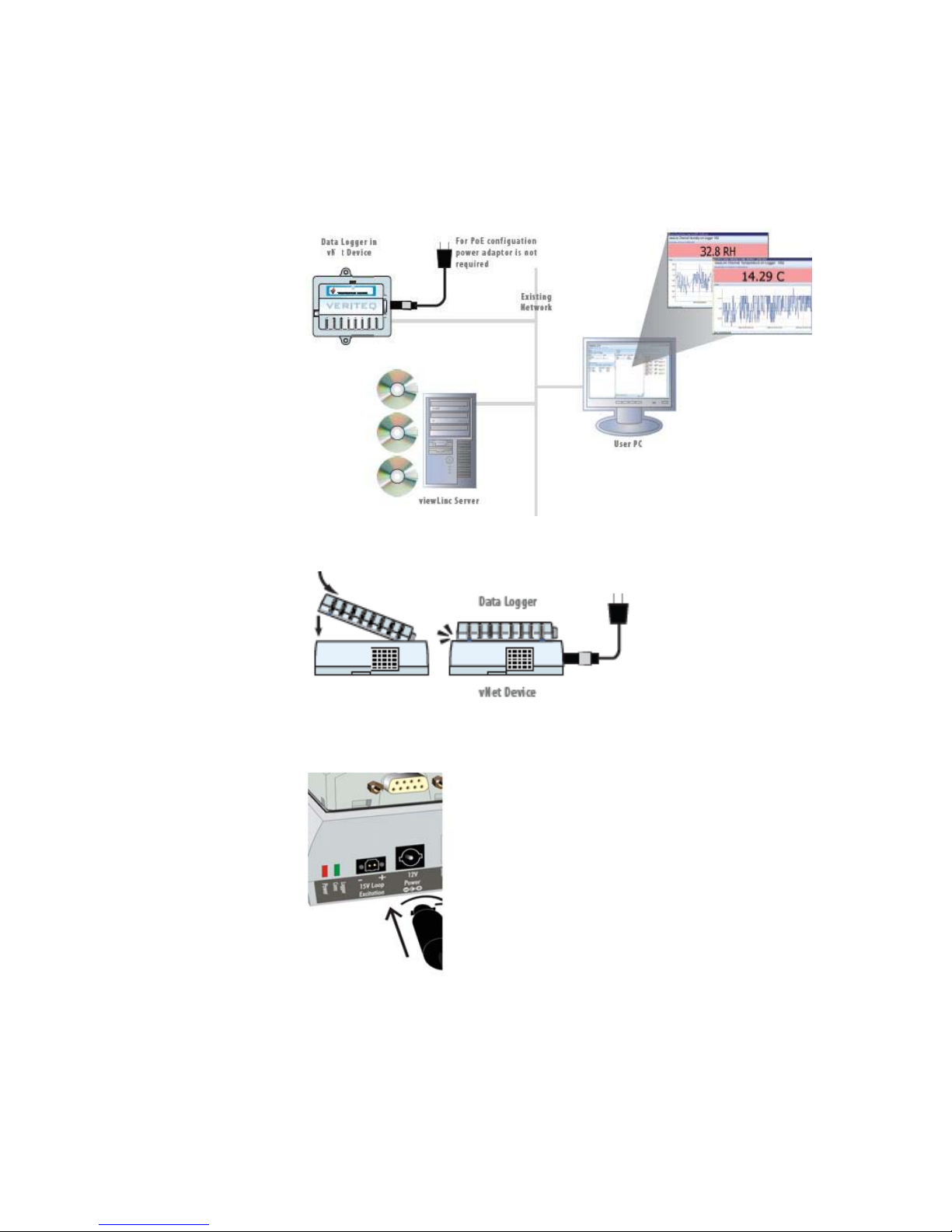
Attaching Main Hardware
1Remove the protective label on the bottom of the data
logger.
2Connect the data logger to the vNet device.
3Connect the vNet device to the power supply and
Ethernet outlet. When power is supplied to the vNet
device, the red power LED will blink for 7-8 seconds,
then stay on. When a network connection is made, the
LNK LED will light up and stay on, and the ACT LED will
blink intermittently.
Note: To ensure a secure connection, insert the power
supply barrel-end connector into the device and
turn 1/4 to the right (see Figure 3 on page 3).
However, if your network supports Power over
Ethernet, you do not need to connect to an exter-
nal power supply .
Installing Drivers Using Device Setup
Device drivers must be installed in Windows®for each of the
vNet or Digi devices that are connected to the network. This
allows the Veriteq software to access the data loggers.
Use the instructions in this section if the drivers will be
installed on a PC that is on the same subnet as the vNet or
Digi devices. If the PC is on a different subnet, use the
Installing Drivers Using RealPort Setup section instead.
1Obtain an IP address for each of the vNet or Digi devices
from your IT department. They should either be reserved
IP addresses supplied by DHCP or static IP addresses. If
the IP addresses are being reserved, the DHCP server
must be updated before you proceed with the installation.
2Insert the Veriteq vNet Device Drivers CD into the PC. If
the Software Installation menu does not display
automatically, click Start on the Taskbar, then select
Run. Type D:\setup.exe (replace ‘D’ with the drive letter
of your CD-ROM drive), then click OK.
3Additional information can be found on the CD by clicking
on Documentation Index on the Software Installation
menu. Click on vNet PoE Readme to see if there areany
updates to the information in the User Guide, especially
to the installation instructions. For information on Digi

vNet Power over Ethernet Device User Guide 5
devices, click on Digi Documentation Index, then select
the desired document for the Digi device you will be
using.
4Click on Device Setup Wizard on the Software
Installation menu.
5Connect the vNet PoE Logger Interface or Digi device to
an open Ethernet port on your network. If the device and
your network both support Power over Ethernet, an
external power supply is not needed. Otherwise, connect
the power supply barrel plug into the vNet or Digi device
(see Figure 3 on page 3), and plug the power supply into
a wall outlet.
6When the Welcome to the Digi Device Setup Wizard
screen is displayed, click Next.
7Scroll down the device list until you find the MAC address
of the device you are installing. (The MAC address is on
the side of the vNet device above the serial number, or
on the bottom of the Digi device.) If the device does not
appear in the list, wait a few seconds, then click Refresh.
Select the device, then click Next.
Note: If the device you are installing is not shown, you
may need to change some settings in your fire-
wall software:
•Allow the dgrunwiz.exe and dgcfgwiz.exe programs
to receive incoming network connections. You will
find these programs in a folder similar to:
C:\Documents and Settings\user\Local
Settings\Temp\RarSFX0 where ‘user’ is
your Windows®account.
•Unblock UDP port 2362 and multi-cast address
224.0.5.128,astheseareusedbydevicediscovery.
8Specify the IP settings:
• If DHCP will be used to supply a reserved IP address,
select Obtain IP settings automatically using DHCP,
then click Next.
• If a static IP address will be assigned to the device,
select Use the following IP settings, enter the desired
IP address, Subnet Mask, and Default Gateway, then
click Next.

6 © 2010 Veriteq Instruments Inc.
9From the Scenario List, select RealPort (COM Port
Redirection), then click Next.
10 Ensure the Install Digi RealPort on this computer
checkbox is checked, click Next, then click Next on the
following screen. Wait for the new settings to be saved to
the device. This will take up to 3 minutes, depending on
the device.
11 If you have another device to install, check the
Configure another device checkbox, then click Finish.
Repeat steps 5 through 11.
12 When the last device has been installed, clear the
Configure another device checkbox, then click Finish.
13 A list of all installed devices that use the RealPort driver
will be displayed in the Command Prompt window after a
short delay. Record the COM port number(s) of the
device(s) you installed, as you will need to know them
when using the Veriteq software products. Close the
Command Prompt window by selecting the title bar, then
pressing any key on the keyboard.
14 Refer to the Launching the vNet Configuration and
Management Interface section for further instructions
on opening the web-based interface to change the
password or other settings.
Installing Drivers Using RealPort Setup
Device drivers must be installed in Windows® for each of the
vNet or Digi devices that are connected to the network. This
allows the Veriteq software to access the data loggers.
Use the instructions in this section if the drivers will be
installed on a PC that is on adifferent subnet than the vNet or
Digi devices. If the PC is on the same subnet, use the
Installing Drivers Using Device Setup section instead.
1Obtain an IP address for each of the vNet or Digi devices
from your IT department. They should either be reserved
IP addresses supplied by DHCP or static IP addresses. If
the IP addresses are being reserved, the DHCP server
must be updated before you proceed with the installation.

vNet Power over Ethernet Device User Guide 7
2Insert the Veriteq vNet Device Drivers CD into the PC
where the drivers are to be installed. If the Software
Installation menu does not display automatically, click
Start on the Taskbar, then select Run. Type
D:\setup.exe (replace ‘D’ with the drive letter of your CD-
ROM drive), then click OK.
3Additional information can be found on the CD by clicking
on Documentation Index on the Software Installation
menu. Click on vNet PoE Readme to see if there are any
updates to the information in the User Guide, especially
to the installation instructions. For information on Digi
Devices, click on Digi Documentation Index, then
select the desired document for the Digi device you will
be using.
4If you are installing a vNet device, click onvNet RealPort
Setup on the Software Installation menu. If you are
installing a Digi device, click on Digi RealPort Setup.
Note: It is very important to select the correct setup
option. If you accidentally select the wrong
option, click Cancel when the Welcome screen
is displayed.
5If the Welcome screen asks you to ensure that the device
is powered up and connected to the network, disregard
the message and click Next. If the Add a New Device
option is displayed instead, select it, then click Next.
6Scroll to the bottom of the device list, wait until
“Searching...” is no longer displayed, select <Device not
listed>, then click Next.
7Enter the Device Model Name. For a vNet device this
name is on the serial number label, for example, CDL-
VNET-P. The model name for a Digi device typically
appears on the top and bottom of the device, for
example, Digi One SP or PortServer TS 4.
8Enter the IP address that you obtained in step 1.
9Under COM Port Settings set No. Ports to 1 for a vNet
device. For Digi devices specify the number of ports
supported by the device, usually 1,2 or 4.
10 Under COM Port Settings, set Starting COM to the
lowest COM port number that the setup wizard is allowed
to use. The wizard will automatically choose the first

8 © 2010 Veriteq Instruments Inc.
available Windows COM port and map it to the first
physical port on the device. If the device has more than
one physical port, the wizard will assign the next
available COM port(s) to the remaining physical port(s).
Note: The Windows Device Manager can be used to
change the assigned COM port number(s) after
the device is installed.
11 Click Finish.
12 If your vNet or Digi device is not yet connected to the
network, or is not yet configured with the IP address you
entered in step 8, you will be presented with a message
indicating that no device could be located. Click Yes to
proceed.
13 Wait for the setup wizard to finish. This could take up to
3 minutes. Click Finish.
14 A list of all installed devices that use the RealPort driver
will be displayed in the Command Prompt window after a
short delay. Record the COM port number(s) of the
device(s) you installed, as you will need to know them
when using the Veriteq software products. Close the
Command Prompt window by selecting the title bar, then
pressing any key on the keyboard.
15 Repeat steps 4 through 14 for any additional devices that
need to be installed. Do not continue with step 16 until all
devices have been installed.
16 If any of the vNet or Digi devices you installed drivers for
are not yet connected to the network, connect them to an
open Ethernet port on the desired subnet of your
network. If the device and your network both support
Power over Ethernet, you do not need an external power
supply. Otherwise, connect the power supply barrel plug
into the vNet or Digi device (see Figure 3 on page 3) and
plug the power supply into a wall outlet.
17 If all of the vNet or Digi devices you installed are using IP
addresses reserved with DHCP, go to the Launching
the vNet Configuration and Management Interface
section for further instructions on opening the web-based
interface to change the password or other settings.
However, if one or more of the devices are to have static
IP addresses assigned, proceed with step 18.

vNet Power over Ethernet Device User Guide 9
18 Insert the Veriteq vNet Device Drivers CD into a PC that
is on the same subnet as the device(s) you installed. If
the Software Installation menu does not display
automatically, click Start on the Taskbar, then select
Run. Type D:\setup.exe (replace ‘D’ with the drive letter
of your CD-ROM drive), then click OK.
19 Click on Device Discovery Install on the Software
Installation menu to install the Digi Device Discovery
program onto this PC.
20 Run the Digi Device Discovery program from Start I
Programs. The program will display a list of all vNet and
Digi devices found on this subnet.
Note: If the device you need to configure is not shown,
you may need to change some settings in your
firewall software:
•Allow the dgdiscvr.exe program to receive incoming
network connections. It is typically found in the folder
C:\Program Files\Digi\Digi Device Discovery.
•Unblock UDP port 2362 and multi-cast address
224.0.5.128, as these are used by device discovery.
21 Scroll down the device list until you find the MAC address
of a device that is to have a static IP address assigned.
(The MAC address is on the side of the vNet device
above the serial number, or on the bottom of the Digi
device.) If the device does not appear in the list, wait a
few seconds, then click Refresh. Select the device, then
click Configure network settings.
22 Select Manually configure network settings, then
enter the IP Address, Subnet Mask, and Default
Gateway values for this device. Click Save, then click
OK to allow the device to be restarted.
23 Wait until the device has been restarted and the device
list updated.
24 Repeat steps 21 through 23 for each additional device.
25 When all devices have their desired IP address, refer to
the Launching the vNet Configuration and
Management Interface section for further instructions
on opening the web-based interface to change the
password or other settings.

10 © 2010 Veriteq Instruments Inc.
Launching the vNet Configuration and
Management Interface
Your vNet device is shipped with a web-based application,
vNet Configuration and Management Interface. You can use
this application to complete the vNet device configuration
activities.
To launch the vNet Configuration and Management interface
from a Web browser:
1In a Web browser, enter the IP address of your vNet
device (obtained from your IT administrator) or enter the
NetBIOS name. The default NetBIOS name is
VERITEQXXXXXXXX (X denotes the 8-digit serial
number of the vNet device.) If the vNet device has been
configured with a TCP port for HTTP other than the
default value of 80, enter the port number after the IP
address or NetBIOS name, with a colon separating them.
For example:
http://192.168.1.58
http://VERITEQ09075101
http://192.168.1.58:8000
2At the login screen, enter the user name: root.
3Enter the default password: dbps. You can change this
password later (see Changing the Administrator
Password).

vNet Power over Ethernet Device User Guide 11
4Click OK. The vNet Configuration and Management
screen displays:
To launch the vNet Configuration and Management interface
using Digi Device Discovery:
Note: If the vNet device has been configured with a
TCP port for HTTP other than the default value
of 80, you need to launch the interface from a
web browser.
1From the Start menu select Digi | Digi Device
Discovery | Digi Device Discovery.

12 © 2010 Veriteq Instruments Inc.
2Locate your vNet device’s MAC address (found on the
side of your vNet device) in the MAC address list, and
double-click on it to open the login screen.
3Enter the user name: root.
4Enter the default password: dbps. You can change this
password later (see Changing the Administrator
Password).
5Click OK. The vNet Configuration and Management
screen displays:
Viewing Network Configuration Settings
To view vNet device IP settings:
1Launch the vNet Configuration and Management
interface.

vNet Power over Ethernet Device User Guide 13
2From the vNet Configuration and Management interface,
click System Summary.
Note: This summary includes all the important informa-
tion about your vNet device, such as device
name, contact person, current IP address, MAC
address, model name, and firmware version.
Configuring IP Settings
There are three methods to assign an IP address to a Veriteq
vNet device:
1Configure a DHCP server to reserve a specific IP
address for the device (by MAC address) and
automatically assign it to the device.
2Manually assign a static IP address to the device.
3Allow a DHCP server to automatically assign any
available IP address to the device.
Either of the first two methods is recommended. The Veriteq
vNet device has DHCP enabled by default. If your network
does not have a DHCP server, you will need to manually
assign a static IP address.
The last method is not recommended because the DHCP
server could periodically assign a different IP address to the
device. If this occurs, viewLinc and the other Veriteq software
will be unable to communicate with the data logger or the
vNet device until Windows Device Manager is used to

14 © 2010 Veriteq Instruments Inc.
manually reconfigure the device driver to point to the new IP
address.
To manually configure IP settings for your vNet device:
1From the vNet Configuration and Management interface,
choose Configuration | Network | IP Settings.
2Select the option Manually configure the IP Settings
using static values, then enter the IP Address, Subnet
Mask, and Default Gateway supplied by your IT
administrator.
3Click Apply.
4A message will appear stating that the vNet device
needs to be restarted. Click on the here link to restart
the device.
Creating a NetBIOS Name
A NetBIOS name provides an easy way to connect to your
vNet device through a Web browser without having to
remember the device’s IP address.
To access the device using the NETBIOS name, simply enter
the name in the address line of your Web browser:
http://NetBIOSname
The factory default NetBIOS name is VERITEQXXXXXXXX
(X denotes the 8-digit serial number of the vNet device).
To change the NetBIOS name:
1From the vNet Configuration and Management interface,
choose Configuration | Network | IP Settings.

vNet Power over Ethernet Device User Guide 15
2In the NetBIOS name field you can enter up to 15
characters (using letters, numbers, and underscores). Do
not assign the same name to another device.
3Click Apply.
4A message will appear stating that the vNet device
needs to be restarted. Click on the here link to restart
the device.
Changing Ethernet Settings
Depending on the network hub or switch the vNet device is
connected to, you may want to change the Ethernet mode
from the default setting, half-duplex, to full-duplex.
To change the Ethernet settings for your vNet device:
1From the vNet Configuration and Management interface,
choose Configuration | Network | Ethernet Settings.
2Choose the desired Duplex Mode (Half or Full).
3Click Apply.
4A message will appear stating that the vNet device
needs to be restarted. Click on the here link to restart
the device.
Note: The speed setting is fixed at 10Mbit and cannot
be changed.
Editing Serial Port Settings
Use the Serial Port Settings screen to set the TCP port
numbers that the vNet device will use for serial
communication. The vNet device communicates with the
Veriteq data logger through a serial port.
The serial port is accessed by the client PC using serial port
redirector (virtual COM port) software that communicates
over the Ethernet connection using TCP ports. The vNet
device needs to be configured to use the same TCP port as
the serial port redirector software.

16 © 2010 Veriteq Instruments Inc.
About Loopback Test Mode
The loopback test mode should only be enabled when
doing diagnostic tests to solve problems with logger
communication. The Loopback Test Mode checkbox must be
unchecked to communicate with the connected data logger.
Unchecked is the default setting.
When the loopback test mode is enabled, it enters a
diagnostic mode where data received from the client PC is
transmitted back to the PC, but not to the data logger. This
can help to determine if a communication problem is due to
the data logger, the vNet device, or the driver on the PC. A
change to this setting only takes effect when the port is
closed, then reopened. The checkbox is automatically
cleared when the vNet device is restarted, or if more than 1
hour has elapsed since it was checked.
Using RealPort
The serial port on the vNet device can be accessed using the
Digi RealPort protocol. If a RealPort driver is installed on a
client PC, it can be configured to access the serial port using
the RealPort TCP port number.
The factory default setting is 771.
It is important to note that only one RealPort client can
connect to the vNet device at a time. The RealPort driver
should only be installed using a Veriteq vNet Device Driver
installation disk to ensure that the client PC will only connect
to the vNet device when trying to open the serial port. When
the serial port is closed, the TCP connection is also closed,
allowing another client PC to connect to the vNet device.
If the driver is installed from a Digi Software & Documentation
CD, the RealPort driver on one client PC will connect to the
vNet device when the PC starts and keep the TCP
connection open. No other PC will have access to the vNet
device.
If needed, there is a setting in the RealPort driver that can be
changed to permit access from multiple computers (see page
17).
Table of contents
Other Vaisala Network Hardware manuals
Popular Network Hardware manuals by other brands

SUNBA
SUNBA NVR-F8009SE user manual

Sensys Networks
Sensys Networks RTMS Echo quick start guide

Nexcom
Nexcom NSA7150 Quick reference guide

Cisco
Cisco ONS 15216-MD-40-ODD install guide

Ensemble Designs
Ensemble Designs Avenue Express Control Panel Data Pack

Dahua Technology
Dahua Technology Lite N42B1P Series quick start guide