VALBERG MC 60 31MC S 701T User manual

Informations pratiques
C
EN
WARRANTY CONDITION
This product is guaranteed for a period of 2 years from the date of purchase* against
any failure resulting from a manufacturing or material defect. This warranty does not
cover defects or damage resulting from incorrect installation, improper use or abnormal
wear of the product.
*upon presentation of the sales receipt.
FR
CONDITION DE GARANTIE
Ce produit est garanti pour une période de 2 ans à partir de la date d’achat*, contre
toute défaillance résultant d’un vice de fabrication ou de matériau. Cette garantie ne
couvre pas les vices ou les dommages résultant d’une mauvaise installation, d’une
utilisation incorrecte ou de l’usure anormale du produit.
*sur présentation du ticket de caisse.
MADE IN TURKEY
ELECTRO DEPOT
1 route de Vendeville
59155 FACHES-THUMESNIL
FRANCE

Informations pratiques
C
964428 - MC6031MCS701T
06/2023 – V6
USER GUIDE ......................................................02
GUIDE D’UTILISATION.......................................32
Dual fuel cooker
Cuisinière mixte
2/2

2FR
C
2 EN2 EN2 EN
Thanks!
Thank you for choosing this VALBERG product.
Selected, tested and recommended by ELECTRO
DEPOT, VALBERG brand products guarantee simple
use, reliable performance and impeccable quality.
You can be sure of complete satisfaction whenever
you use this product.
Welcome to ELECTRO DEPOT.
Visit our website: www.electrodepot.fr

3FR
Informations pratiques
C
3 EN3 EN
Table of contents
AOverview of the
appliance
CPractical information
BUsing the appliance Installation
Gas connection
Electrical connections and safety
Gas change
Using the cooker
Using the hotplates
Using the oven
Oven functions
Oven accessories
Cleaning and maintenance
Removing the oven door
Cooking recommendations
Connection
Appliance description

4FR
Overview of the appliance
A
Appliance description
1Cover
2Hob
3Control panel
4Oven door handle
5Under oven or drawer front
6Oven door
7Drip tray
8Oven rack
9Grill
10
Oven light
11
Semi-fast cooking
12
Rapid burner
13
Auxiliary burner
14
Pot/pan support rack
15
Electric hob
1
2
3
8
7
6
4 5
9
10
15
12
13 14
11

5FR
Informations pratiques
C
5 EN
Using the appliance
B
Installation
This modern, functional and practical cooker, made with the best parts and materials, will
meet your needs in every aspect. Before using your cooker, please take the time to thoroughly
read these instructions in order to familiarise yourself with all of its features and to obtain the
best results possible. To ensure correct installation and to avoid any issues or hazardous
situations, please take the following recommendations into account. These recommendations
should also be read by the technician installing the cooker.
Installation environment for your cooker
• Your cooker should be installed and used in a place with effective ventilation at all times.
The oxygen in the air means that gas combustion is possible. Therefore, this air must
be renewed and the combustion products must be evacuated in compliance with the
applicable regulations. There must be sufcient natural ventilation in the space where
the cooking appliance is installed in order to allow for gas to be used in the environment.
The average air ow must come in through ventilation systems installed on the walls, in
direct contact with the exterior (see the diagram below).
Section d’entrée
2
Section d’entrée
2
Air inlet section,
min. 100cm²
Air inlet section,
min. 100cm²

6FR
Informations pratiques
C
6 EN
Using the appliance
B
•
The air ow must have a bottom-end inlet (at least 100 cm
2
) and top-end outlet (at least
100 cm
2
). These ventilation systems must therefore have a minimum surface area of 100 cm
2
,
in order to allow for sufcient and effective air circulation. These ventilation systems must be
kept unobstructed at all times. Ideally, they should be located close to the rear of the cooker
(for the air inlet, see gures 1 and 2) and opposite the gas burner points (for evacuation), at
least 1.80 m above the oor. If there is no option in the room where the cooker is installed
to open these ventilation systems out to the exterior, the air required may also come from
another place, on the condition that this place is well-ventilated and is not a bedroom or a
hazardous space.
Flue gas extraction
It is advised to install either an extractor hood connected to a duct that leads directly to the
outside (Fig. 3) or an electric ventilation system installed on the window or outside wall (Fig. 4)
to exhaust the ue gases directly to the outside. The power of the electric ventilation system
must be calculated in order to be able to renew the air of the kitchen 4 to 5 times per hour, of
its own volume of air per hour.
Hotte
aspirante
Section d’entrée
2
Section d’entrée
2
Ventilateur électrique
HOTTE DE LA CUISINIÈRE
Min.
Min.
(avec hotte)
(sans hotte)
Hotte
aspirante
Section d’entrée
2
Section d’entrée
2
Ventilateur électrique
HOTTE DE LA CUISINIÈRE
Min.
Min.
(avec hotte)
(sans hotte)
Cooker
hood
Air inlet section,
min. 100cm²
Air inlet section,
min. 100cm²
HOOD OF THE COOKER
(with hood)
(without hood)
Electric fan

7FR
Informations pratiques
C
7 EN
Using the appliance
B
Installing your cooker
•
The cooker can be placed next to other units, but make sure that the height of the
surrounding units does not exceed the height of the cooker (see Fig. 5).
• If the kitchen units are higher than the cooker, leave a gap of at least 10 cm between the
sides of the cooker and the units.
• The minimum height between the cooktop and the hood (or wall units) is shown in Fig. 5.
The exhaust hood must be placed at least 65 cm from the cooktop. If there is no cooker
hood, there must be a height of at least 70 cm between the cooktop and the unit installed
above it.
•
Leave a free space of 2 cm between the back of the cooker and the wall, and between the
sides of the cooker and adjacent units.
• Ensure that the cooker is not placed near a refrigerator and that there are no ammable
materials in the vicinity, such as curtains, cloths etc., which could catch re quickly.
• Adjacent units must be made from a material that can withstand temperatures of up to
100 °C.
Adjusting the feet
Your cooker has 4 adjustable feet. After installing the cooker in its dedicated space, check that
it is level. To do this, adjust the 4 adjustable feet by screwing or unscrewing them (Fig. 6).
The cooker must be positioned vertically.
It can be adjusted to a maximum height of 30 mm. You can remove the drawer from the cooker
to adjust the height of the feet.
When the feet are correctly adjusted, you should not move the cooker by pulling it, but by lifting
it (ensure not to lift it by the oven door handle).

8FR
Informations pratiques
C
8 EN
Using the appliance
B
Gas connection
Gas connection and leak checks
The cooker must be connected to the gas supply by a qualied technician in compliance with
the applicable standards (in line with Article 10 of the Decree of 02-08-1977 and Building
Code regulations 61-1 which impose the presence of a control valve at the end of the pipe for
natural gas, with a pressure release trigger in compliance with the NF D 36-303 standard.
This control valve must allow for the gas supply to be shut off when the cooker is not in use).
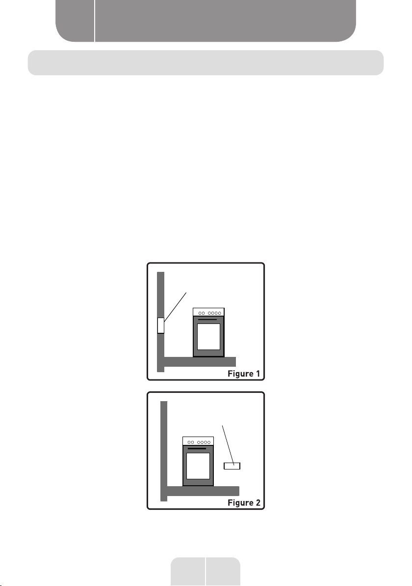
Firstly, check the type of gas installed on the cooker. This information is indicated on a label
at the back of the cooker. You'll nd information regarding the types of gas and injectors in the
technical specications table. Make sure that the in-ow gas pressure is compliant with the
values specied in the technical specications table in order to guarantee optimal efciency
and minimum gas consumption. If the pressure of the gas used is not the same as these values
or variables, you'll need to add a pressure regulator to the in-ow pipe. We advise that you
contact the after-sales service in order to take these measurements and apply adjustments.
Butane (G30) - propane (G31) gas connection
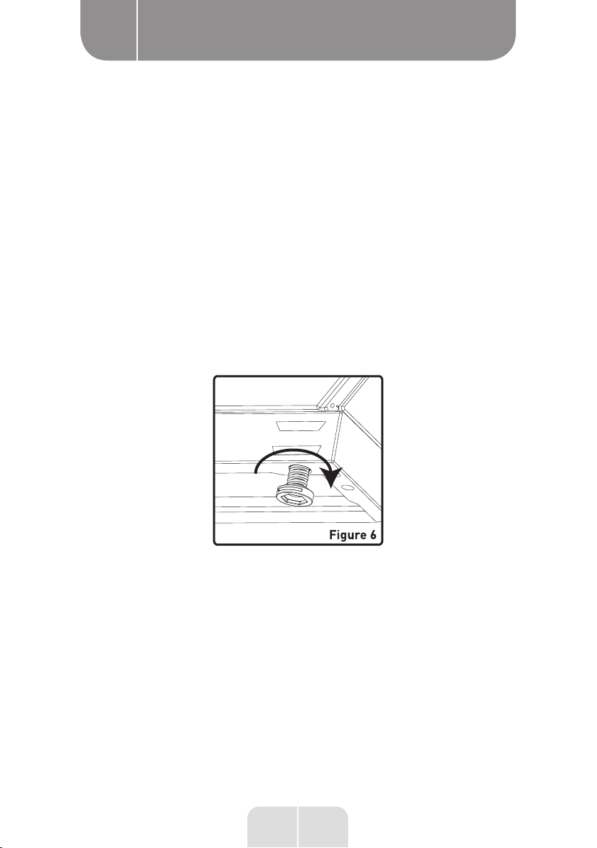
The technician must rst check the gas setting of your cooker. If it has a natural gas supply,
they will need to change the injectors (see below), so that it can be used with butane gas.
The installation can be carried out either with a butane/propane specic gas hose sold with
2 clamps, or with a hose with a mechanical tip with mounted ttings.
If you would like to use a hose with a mechanical tip:
• use the tting supplied with the GN spare parts;
• ensure that the hose you are using complies with NFD 36112 or NFD 36125 standards:
• always use a gasket between the tting and the gas inlet.
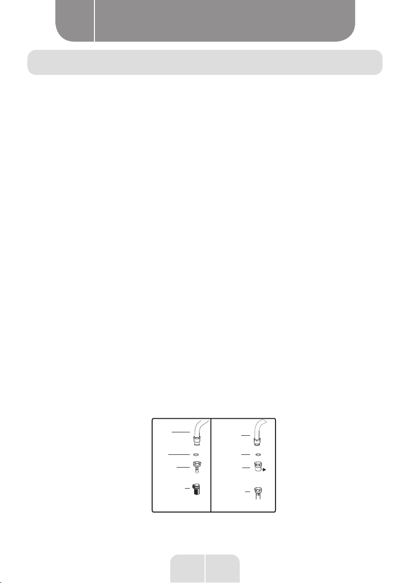
If you are tting a butane/propane hose with a clamp, the butane gas connector with the
gasket must be tted to the cooker, the hose must be pushed all the way onto this connector
and a clamp must be tted, tightening it properly but not cutting the hose. Do the same on
the regulator side (see Fig. 7).
The maximum length permitted is 1.50 m.
(TFEM)
Adaptateur
Tuyau
de gaz
Joint
Joint
Mécanique
(TFEM)
Tuyau de gaz
Tuyau
de gaz
Tuyau
Raccord
(TFEM)
Tuyau de gaz
(TFEM)
Avec col
G1/2
FR
Adaptateur
Tuyau
de gaz
Joint
R1/2
BE
Mécanique
Tuyau de gaz
Mécanique
Tuyau de gaz
Tuyau de gaz
Avec col
Adaptateur
Tuyau
de gaz
JointJoint
Tuyau
de gaz
Tuyau
Raccord G1/2
ES
Gas
hose
EN
Seal
Hose
connector
Gas hose
with clamps
Gas hose
Seal
Adapter
Ad Mecanic
gas hose
apter

9FR
Informations pratiques
C
9 EN
Using the appliance
B
It is extremely important that you note and adhere to the expiry date indicated on the hose
and to change the hose prior to this date in order to guarantee safety. If you are tting a hose
with a mechanical tip, the butane gas nozzle is not required. Simply screw the ttings of the
hose with a mechanical tip on the cooker side and the cylinder side (tighten properly with 2
spanners as shown in the diagram above).
Natural gas connection (G20/G25)
The technician will have to install a pipe with a mechanical tip according to the NFD
36100/36103/36121 standard and connect the cooker according to the regulations in force.
Complies with Belgian installation standards: NBN D 51-003 et BNB D 51-006
Points to respect when connecting the gas supply hose:
•
No part of the hose should come into contact with a surface reaching temperatures above
90 °C. There must be a distance of at least 20 mm between the hose and hot elements.
• The hose length must not be longer than 1.50 m.
• The hose must not be cut, compressed or bent.
•
The hose must not be defective and must not come into contact with sharp or cutting
edges, or with moving objects.
•
The hose must be thoroughly checked prior to installation, in order to make sure that
there are no manufacturing faults.
•
When the gas is connected, the hose must be inspected for leaks by a qualied technician
using a specic bubble device. No bubbles should appear. If bubbles appear, check the
connection seal and repeat the test. During these tests, never use a lighter, matches, etc.
• The butane gas hose clamps must not be rusted.
• The hose's validity date must be checked regularly.
WARNING
Do not use lighters or matches to check for gas leaks.

10 FR
Informations pratiques
C
10 EN
Using the appliance
B
Electrical connections and safety
You must follow the instructions below for the cooker's electrical connection.
The electrical connection must be carried out by a qualied individual, in line with the
applicable standards.
• The appliance must be connected by an authorised person. You must use a H05W-F type
power cable. The cooker has been designed to be connected via a permanent connection
with the electrical network.
•
The connection must use a grounding plug. If you don't have a grounding plug that is
compliant with regulations, contact a qualied installation technician.
•
A compatible power cable that can be appropriately isolated during the connection process
must be used. If the cable is damaged, contact the after-sales service. The power cable
should only be replaced by the after-sales service.
• The power socket must be located close to the cooker. Do not use an extension cord.
•
Ensure that the power cable does not touch the hot surfaces of the cooker or the back
of the appliance. This could damage the cable or the cooker, or cause a short circuit.
• Incorrect electrical connection may damage the cooker. Such damage is not covered by
the guarantee.
• The cooker is designed for a connection of 220-240 volts and 400 V 3 N. If your electrical
network has a different voltage, please immediately contact a qualied installation
technician.
•
Arrange for the installation of a two-pole time-delay circuit breaker, with a minimum
distance of 3 mm between the contacts and rated at 32 A.
• The manufacturer may in no way be held liable in the event of damage or loss caused by
any failure to comply with these safety instructions.
L3
L2
L1
34
5
N
PE
2
1L
3
4
5
N
PE
2
1

11 FR
Informations pratiques
C
11 EN
Using the appliance
B
Gas change
WARNING
The following procedures must be carried out by a qualified
technician.
Your cooker has been designed to operate with either liqueed petroleum gas (butane or
propane) or natural gas. The burners can be adapted to these different gas types by replacing
the corresponding injectors and adjusting the minimum ame length of each burner. The
following steps must be taken: Procedure for changing injectors:
Hob burners:
• Shut off the main gas supply and unplug the electrical socket.
• Remove the burner cap and the upper burner (gure 9).
• Unscrew the injectors. Use a 7 mm allen key to do this (gure 10).
•
Position the new injectors, in line with the correct gas type used, using the technical
information table as a reference. Make sure that the new injectors are screwed on straight.
If you assemble them at an angle, you risk damaging the support moulding and the support
will then need to be replaced (not covered by the guarantee).
Clé à molette
Injecteur
Pipe spanner
Injector

12 FR
Informations pratiques
C
12 EN
Using the appliance
B
Adjusting the ame height at the minimum valve position
The ame height can be adjusted to the minimum position with a at screw located at the
valve. For valves with thermocouples, the screw is located on the side of the valve stem (Figure
11). On cookers with thermocouple and micro switch (automatic ignition), it is advisable to
remove the control panel during the operation, in order to facilitate the adjustment of the
ame height to the minimum position.
To determine the minimum position, turn on the burners one by one and leave them in
the minimum position. Using a small screwdriver, tighten or loosen the bypass screw by
approximately 90°. The adjustment is correct when the ame reaches a height of at least 4
mm. Make sure that the ame does not go out when adjusting it from the maximum position
to the minimum position. Use your hand to create an articial breeze, in the direction of the
ame, to check that it is stable.
When switching from GL to GPL, this same screw must be tightened as much as possible.
Vis de dérivation
Robinet avec dispositif thermocouple
Replacing the gas supply hose:
Regularly check the expiry date of the gas hose of your cooker. When the validity limit is
reached, the hose must be changed.
These hoses are commercially available and must comply with current standards. After
replacing the hose, check for leaks by referring to the information in the section above: Gas
connection and leak checks.
Valve with thermocouple device
Bypass screw

13 FR
Informations pratiques
C
13 EN
Using the appliance
B
Using the cooker
Using the hob burners
Burner ignition
The symbols on the knobs on the front panel indicate the position of the burners.
Gas burner manual ignition
If your cooker does not have electrical ignition or if the electrical network is down, please
follow the procedures described below:
For hob burners with thermocouple: the cooktops equipped with a thermocouple safety device
ensure safety when the ame is accidentally extinguished. For this reason, when igniting
manually, keep the valve knob pressed in until the ames have stabilised. If the ame remains
unstable after you’ve released the control knob, repeat the procedure from the start. When
the ame goes out, the thermocouple system will shut off the gas supply from the concerned
valve to the burner, avoiding any non-combusted gas accumulation. You must wait at least 90
seconds before turning the gas burner on again after an automatic cut-off.
Electric ignition
Ignition with the help of automatic ignition: To light one of the burners, press the knob on the
relevant valve counter-clockwise until it is in the maximum position (clockwise for the grill
burner). Hold the knob down so that the ignition generates sparks. The microswitch behind
the knob will automatically produce sparks at the burner spark plug. Continue to press the
button until a stable ame is obtained on the burner.
Explanation of the thermocouple safety device: a thermostat detects the burner's ame and
keeps the gas supply open. When the ame goes out, the thermostat detects the loss of heat,
and closes the gas supply valve.
Position Arrêt Position MAXI Position MINI Intermédiaire
Off position Max position Min position Middle

14 FR
Informations pratiques
C
14 EN
Using the appliance
B
The valve knobs on the cooktop have 3 positions: Off (0), Max (large ame symbol), and Min
(small ame symbol). After having ignited the burner and set it to the ‘Max’ position, as explained
above, you have the option to adjust the ame height between the ‘Max’ and ‘Min’ positions.
Avoid setting the knob to between the ‘Max’ and ‘Off’ positions.
Chapeau
Couronne
Bougie
d’allumage
Brûleur
inférieur
After ignition, visually check the ames. If you can see a yellow tip or suspended or unstable
ames, turn off the gas supply and check that the burner caps and crowns are correctly positioned
(Fig. 13). Caution, these elements are extremely hot; wait for them to cool to avoid burns. Make
sure that no liquid runs into the burners. If the ames accidentally are outside of the burner,
close the valves, air the kitchen with fresh air, and wait at least 90 seconds before igniting the
burner again.
To stop cooking, turn the burner knob clockwise until the mark on the knob is opposite the ‘0’
point (the mark on the knob must be up).
Your cooker is tted with burners with different diameters. In order to make sure the burners
are functioning efciently, take note of the size of the pots/pans placed on the burners, and use
perfectly level pans. Don't use pans with a concave or convex base, in order to avoid energy loss.
Make sure the size of the pots/pans corresponds to the ame. If you’re using pots/pans which
are smaller than those specied below, this may cause energy loss. To use gas as economically
as possible, set the ame to the minimum position once boiling point has been reached. We
advise that you always cover your cooking pot/pan.
Rapid burner: 22-26 cm
Semi-rapid burner: 14-22 cm
Auxiliary burner: 12-18 cm
Burner cap
Ring
Spark plug
Lower burner

15 FR
Informations pratiques
C
15 EN
Using the appliance
B
When the hob is not used for an extended period of time, always turn off the gas supply valve.
WARNING
• Only use pots/pans with flat and sufficiently thick bases.
• Ensure that the base of the pan is dry before positioning
it over the burners.
•
Parts exposed to the flame can reach extremely hot
temperatures during use. This is why you must keep
children and animals out of reach of the burners when
in use.
• The cooker hob remains hot for a long period after use.
Do not touch and do not place any objects on it.
•
Avoid placing knives, forks, spoons and other cutlery onto
the cooker hob, as they will heat up and may cause serious
burns.

16 FR
Informations pratiques
C
16 EN
Using the appliance
B
Using the hotplates
There are two types of hotplates:
• standard hotplates;
• rapid hotplates (which can be identied by a red dot on the surface of the hot plate).
These hotplates are controlled by a 6-position knob.
When you move the control knob to one of these positions, the hotplate starts to operate.
Under each button you will see a small diagram that indicates the corresponding hotplate.
An indicator light on the control panel shows whether one of the hotplates is on.
Hotplates - Functions
0 Off position
1 Melt butter or other substances. Heat small quantities of liquids.
2 Heat larger quantities of liquids. Make creams and sauces
3 Defrost foods to cook.
4 Preparing fine meat and fish.
5 Roast meat and steak.
6 Boiling large quantities of liquids for cooking.

17 FR
Informations pratiques
C
17 EN
Using the appliance
B
WARNING
When the hotplate is used for the first time, or if it has
not been used for an extended period of time, you should
remove any moisture that has accumulated around the
electrical components of the hotplate, by switching the
hotplate on for at least 20 minutes.
• Only use pots/pans with at and sufciently thick bases.
• Never use pots/pans smaller than the diameter of the hotplate.
•
Ensure that the base of the pot/pan is dry before positioning it over the hotplate. When
the hotplate is switched on, it is important to ensure that the pot/pan is correctly centred
on the hotplate.
• Do not use cooking pots/pans which exceed the edge of the hob, which risks overheating
the control knobs.
Figure 16
CORRECT INCORRECT INCORRECT
Fond de casserole incurvé
INCORRECT
Petit diamètre de casserole Le fond de la casserole est mal placé
• Never use the hob without pots/pans on the hotplates.
• The temperature of exposed parts may be high when the appliance is in use. This is why
you must keep children and animals out of reach of the hotplates when in use.
• If you discover a crack in the hotplate, turn it off immediately and have it replaced.
•
To prolong the life of your hotplate, it should be thoroughly cleaned with appropriate
cleaning agents. To prevent rusting and to keep them looking new, it is advised to polish
the hotplates lightly with a piece of cloth soaked in a little oil. Do not clean with steam
cleaners.
•
The hotplates remain hot for a long time after use. Do not touch them or place objects
on them.
Curved pan base Small pan diameter The pan base is incorrectly
placed

18 FR
Informations pratiques
C
18 EN
Using the appliance
B
Using the oven
50
100
150
200
250
Max
Control knob of the oven functions:
This knob is used to select the different functions of the oven; the explanations are given in
the following section. Set the control knob to the chosen function, then select the temperature
to switch on the oven.
50
100
150
200
250
Max
Oven thermostat knob:
This knob is used to select the temperature (after selecting an oven function). When you select
a temperature, the oven light comes on. When the temperature inside the oven reaches the
value you have indicated, the thermostat switches off the heating elements and the indicator
light goes out. When the temperature drops below the set value, the thermostat reconnects
the heating elements and the thermostat light comes on again.

19 FR
Informations pratiques
C
19 EN
Using the appliance
B
Oven functions
* The functions of your oven may differ depending on the model of your appliance.
Oven lamp
Only the oven light will remain on during all cooking functions.
Defrosting function
The warning indicator lights of the oven light up, the fan is operating.
To use the defrost function, take the frozen food out and put it in the oven on a level set in the
third slot from the bottom. It is recommended that a tray be placed under the defrosting food
to catch the water from the defrosting process. This function does not allow you to prepare
or cook your food. It only allows you to defrost them.
Static cooking function
The thermostat and oven warning indicator lights come on, and the upper and lower heating
elements switch on.
The static cooking function emits heat, which ensures that the food is cooked evenly on the
lower and upper levels. This function is ideal for baking doughs, cakes, baked pasta dishes,
lasagne and pizzas. With this function, it is recommended to preheat the oven for 10 minutes
and to cook one dish at a time.
Fan function
The thermostat and oven warning indicator lights come on, and the fan and the upper and
lower heating elements switch on.
This function is particularly suitable for baking. The cooking process is carried out by the upper
and lower heating elements inside the oven and by the fan, which circulates the air, giving
the food a slight grilled effect. It is recommended to preheat the oven for about 10 minutes.
Turbo function
The thermostat and oven warning indicator lights come on and the upper heating element
and fan switch on.
The turbo function disperses the heat in the oven. All food on the tray cooks evenly. It is
recommended to preheat the oven for about 10 minutes.
This manual suits for next models
1
Table of contents
Languages:
Other VALBERG Cooker manuals