Valcom Clarity SMB-200 User manual

1 947443
Issue 3
SMB-200
200 WATT 2-CHANNEL POWER AMPLIFIER
INTRODUCTION
These instructions contain the specifications and
information necessary to install, operate, and maintain
the SMB-200, 200 Watt 2-Channel Power Amplifier.
"WARNING: To reduce the risk of fire or
electric shock, do not expose this appliance
to rain or moisture."
"WARNING: Shock Hazard - Do Not Open."
"AVIS: Risque de Choc Electrique ne pas
Ouvrir."
SPECIFICATIONS
Purpose
The SMB-200 2-Channel Power Amplifier provides
up to 100 Watts of audio power per channel in the
2-channel mode and 200 Watts of audio power in
bridge mode for voice paging and/or background
music systems.
Applications
Clarity Paging and Sound Reinforcement
Systems
Clarity Stand Alone Background Music Systems
Features
- 100 Watts per channel
- Shelf or rack mount (optional rack kit SMA-RMK)
- Volume control for each channel
- ON/OFF switch
- Circuit breaker protection
- Overload limiting circuit protection
- Phono jacks for input connections
- Screw terminals for output connections
- Power "ON" indicator per channel
- Clipping indicator per channel
- 2 Ohm output in 2-channel mode
- 4 Ohm output in bridge mode
Dimensions and Weight
17.125" W x 3.5" H x 16" D
(43.5 cm W x 8.89 cm H x 40.64 cm D)
28.5 lbs. (12.9 kg)
Accessories
SMB-101 Wall or shelf mount 100 Watt
2-channel transformer unit (25/70/100 Volt)
10.0” W x 4.5” H x 7.0” D
(25.4 cm W x 11.43 cm H x 17.78 cm D)
13.2 lbs. (5.99 kg)
SMB-102 Wall or shelf mount 200 Watt
1-channel transformer unit (70/100 Volt)
10.0” W x 4.5” H x 7.0” D
(25.4 cm W x 11.43 cm H x 17.78 cm D)
11.9 lbs. (5.4 kg)
SMB-201 Rack mount 100 Watt 2-channel
transformer unit (25/70/100 Volt) (3 RU)
19.0” W x 5.25” H x 3.5” D
(48.26 cm W x 13.34 cm H x 8.89 cm D)
12.8 lbs. (5.81 kg)
SMB-202 Rack mount 200 Watt 1-channel
transformer unit (70/100 Volt) (3 RU)
19.0” W x 5.25” H x 4.0” D
(48.26 cm W x 13.34 cm H x 10.16 cm D)
11.2 lbs. (5.08 kg)
SMA-RMK Rack mount kit that extends
width of SMB-200 for installation into 19”
racks.
Nominal Specifications
Wattage Output 100 Watts RMS per channel
200 Watts RMS Bridge
Type Outputs 2- channel mode, 2 Ohms
Bridge mode, 4 Ohms
Frequency Response 50-25 kHz + 2 dBm
Distortion <.5% @ 1 kHz Rated Output
S/N Ratio <80 dBm
Input Impedance 10k Ohms
Sensitivity 500 mVRMS
Contour roll off 300 Hz, 6 dBm per octave
Mounting Wall or Rack
Power Requirements
Voltage 120 Vac
Current 5.0 Amps

2 947443
FIGURE 1
SMB-200 2 CHANNEL POWER AMPLIFIER
FRONT PANEL DESIGNATIONS
Environment
Temperature 0 to 50°C
Humidity 0 to 85% non-precipitating
DESIGN
The SMB-200 100 Watt 2-Channel Amplifier is
designed to provide 100 Watts of audio power per
channel in the 2-channel mode or 200 Watts in the
bridge mode.
The SMB-200 amplifier can be used to operate
2 Ohm speaker loads in the 2-channel mode or a
4 Ohm load in the 200 Watt bridge mode.
The amplifier has an input volume control for each
channel located on the back of the unit.
Circuit breakers are provided on the back of these
units and will operate in the event of a catastrophic
overload. The 2-channel amplifier contains limiting
circuits for protection against short circuits or
impedance mismatches. The units will shut down in
the event of a trouble condition and reactivate
automatically when the condition is corrected.
The amplifiers can be either shelf or rack mounted
(rack mount kit is optional).
INSTALLATION
General
Figures 2 and 3 show volume control locations,
output terminal strips and switches on the back of the
amplifier as well as typical connections to
mixer-amplifiers.
Mounting
The SMB-200 is designed for shelf or rack mounting.
Make certain the unit is not mounted near heat
sources or strong magnetic fields. Verify control and
terminal strip accessibility. The unit may be rack
mounted. Order the associated rack mount kit
SMA-RMK.
Input Connections
High impedance auxiliary devices such as mixers,
equalizers, mixing boards, etc. can be connected to
channel A or B. Phono jacks are provided at the rear
of the amplifier for each channel input.
Speaker Cabling
Standard two conductor speaker wire can be used
(14-20 AWG determined by the load).
Amplifier Setup
During initial system set up, it is recommended that
the channel A and B input gain controls be set 1/4
turn clockwise.
All connections should be made to the
amplifier and double-checked before the ac
power cord is plugged in. This includes any
optional external output transformers and
speaker loads connected to them.
The power indicators will illuminate when the ac
power cord is plugged in and the power switch is in
the "ON" position.

3 947443
OPERATION
General
The SMB-200 provides two modes of operation,
2-channel (100 Watts per channel) or 1-channel mono
(200 Watts bridged).
When the amplifier is in the 2 channel mode signals
are applied to both the channel A and B inputs.
Channel A and B outputs are connected to their
respective speaker loads. The output levels are
controlled by the channel input volume controls. In
the event that low frequency content is not required to
the speaker load, i.e. paging horns, the contour switch
may be placed in the “ON”position and frequencies
below 300 Hz will be reduced at a rate of 6 dBm per
octave. See Figure 2 for details.
When the amplifier is used in the bridge mode, the
mode switch located on the back of the amplifier is
placed in the “Bridged Amp” position. The input
signal is applied to Channel A. The speaker load is
connected between the Channel A and Channel B
2 ohm output terminals. The Channel A volume
control is used to adjust the volume level of the
speakers. In the event that low frequency content is
not required to the speaker load, i.e. paging horns, the
contour switch may be placed in the “ON”position
and frequencies below 300 Hz will be reduced at a
rate of 6 dBm per octave. See Figure 3 for details.
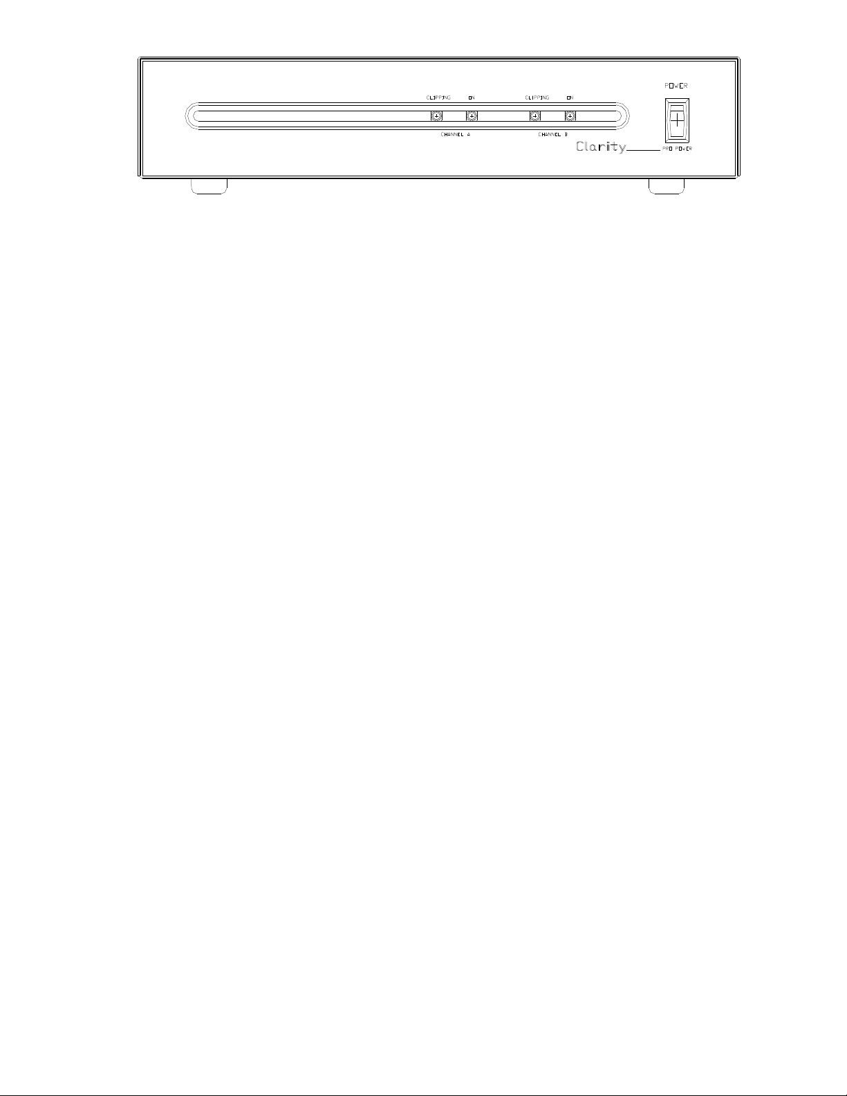
Clipping lights are provided on the front of the unit.
These lights will illuminate when the output signal
exceeds the power rating of the amplifier. There are
also 2 power lights located on the front of the unit
that will illuminate when the unit is connected to a
120 Vac power source and the power switch is in the
“ON”position. See Figure 1 for details.
TECHNICAL ASSISTANCE
When trouble is reported, verify that ac power is
being supplied to the unit and there are no shorts or
grounds on the speaker cabling. Assistance in
troubleshooting is available from the factory. You
should call from the job site and have a VOM (Volt-
Ohm meter), telephone test set and appropriate hand
tools available. Call (540) 767-1550 and ask for
technical support. Visit our website at
http://www.clarity-com.com.
CLARITY maintains service facilities in Roanoke,
VA. Should repairs be necessary, attach a tag to the
unit clearly stating company name, address, phone
number, contact person and the nature of the problem.
Send the unit to:
Repair and Return Dept.
Clarity
5614 Hollins Road
Roanoke, VA 24019-5056
TROUBLESHOOTING CHART
PROBLEM
POSSIBLE SOLUTION
No output.
1. Verify ac power is being supplied to the unit and the power switch
is in the "ON" position and both power lights are illuminated.
2. Verify that input signal is present at amplifier connection.
3. Verify all speaker wiring (no opens, shorts or grounds).
Distorted output.
1. Check input wiring for proper polarity connections.
2. Verify that speaker load does not exceed amplifier rating.
3. Verify input signal does not exceed input voltage rating.
4. Verify all speaker wiring (no opens, shorts or grounds).

4 947443
FIGURE 2
REAR CONNECTIONS –DUAL AMP MODE
FIGURE 3
REAR CONNECTIONS –BRIDGED AMP MODE
CLARITY LIMITED WARRANTY
Clarity warrants its products only to the original purchaser, for its own use, to be free from defects in materials and workmanship under conditions
of normal use and service for a period of one year from the date of shipment. This Limited Warranty obligation shall be limited to the replacement,
repair or refund of any such defective device within the warranty period, provided that:
1. inspection by Clarity indicates the validity of the claim;
2. the defect is not the result of damage, misuse or negligence after the original shipment;
3. the product has not been altered in any way or repaired by others and that factory sealed units are unopened (a service charge plus parts
and labor will be applied to units defaced or physically damaged);
4. freight charges for the return of products to Clarity are prepaid;
5. all units 'out of warranty' are subject to a service charge. The service charge will cover minor repairs (major repairs will be subject to
additional charges for parts and labor).
This Limited Warranty is in lieu of and excludes all other warranties, expressed or implied and in no event shall Clarity be liable for any
anticipated profits, consequential damages, loss of time or other losses incurred by the buyer in connection with the purchase,
operation, maintenance, installation, removal or use of the product. The maximum liability of Clarity under this warranty is limited to the
purchase price of the specific Product covered by the warranty.
Disclaimer. Except for the Limited Warranty provided herein, the product is provided “as-is” without any warranty of any kind whatsoever including,
without limitation, any WARRANTY OF MERCHANTABILITY, FITNESS FOR A PARTICULAR PURPOSE OR NON-INFRINGEMENT.
This warranty specifically excludes damage incurred in shipment. In the event a product is received in damaged condition, the carrier should be
notified immediately. Claims for such damage should be filed with the carrier involved in accordance with the F.O.B. point.
Headquarters:
Clarity
5614 Hollins Road Roanoke, VA 24019-5056
Phone: (540) 767-1550 FAX: (540) 362-9800
Other Valcom Amplifier manuals