Valcom V-9927A User manual

947926
1
Issue 6
V-9927A
DIGITAL MULTI-TONE GENERATOR
INTRODUCTION
The V-9927A was designed with ease of
installation and flexibility in mind. Connections
are by screw terminals located on the edge of
the PCB. The various options and tones are set
using option blocks located inside the enclosure
on the PC Board.
The V-9927A is a microprocessor controlled
multi-tone generator capable of producing a
variety of tone signals for various applications. It
is functional and backward compatible with the
previous V-9927.
Note: Double check all wiring as
connections to the unit are different.
This equipment has been tested and found to
comply with the limits for a Class A digital device
pursuant to Part 15 of FCC Rules. These limits
are designed to provide reasonable protection
against harmful interference when this
equipment is operated in a commercial
environment. This equipment generates, uses
and can radiate radio frequency energy and if
not installed and used in accordance with the
instruction manual, may cause harmful
interference to radio communications. Operation
of this equipment in a residential area is likely to
cause harmful interference in which case the
user will be required to correct the interference
at his/her own expense.
SPECIFICATIONS
Power Requirements
-24VDC “B” Battery at 100mA
Nominal Input/Output Specifications:
Input Impedance: 600 Ohms
Output Impedance: Less than 4 Ohms
Min. Output Load Impedance: 20 Ohms
Audio Input: 0dBm nominal
Maximum Tone Output: >0dBm single tone
Operating Environment:
Temperature: 0 to +50° C
Humidity: 0 to 85% (non-condensing)
Dimensions & Weight
8.20 "H x 4.55 "W x 2.30 "D
(20.83cm H x 11.56cm W x 5.84cm D)
Weight: 1.5 lbs (0.68 kg)
INSTALLATION
Product is intended for wall mounting only.
When mounting, open enclosure and remove
circuit board. Screw back of enclosure to
backboard near the telephone system common
equipment. Snap circuit board back in place.
Both mounting holes must be utilized to
insure secure mounting of the unit.
Make connections and set tones, using option
blocks, as required for the specific application
Refer to Tone Table on page 2 for tone
descriptions.
Replace cover and plug in power supply.

947926
2
OPERATION
All Tones (except Code Call)
Operation of the V-9927A is accomplished by
applying a connection between the COM
(Common) terminal on the terminal block and
the desired tone # (1-8).
The Tone selected by terminal number 1 has
priority over others. If multiple tone inputs are
being used, it is possible to sequence tones by
closing the appropriate contacts in the desired
sequence. However, Tone number 1 will always
be placed first on the list when it has been
activated.
If multiple tones are selected at the same time,
the LOWEST tone number will have priority. If
the lowest contact is open, then the next lowest
tone number will be activated.
When a Tone is activated the INPUT source will
be faded out in 0.75 seconds if P5 is out or will
be faded out in 0.25 seconds if P5 is IN.
The V-9927A has a buffer for 32 tones. If more
than 32 tones are entered within a short period,
the V-9927A will drop the last tone entered
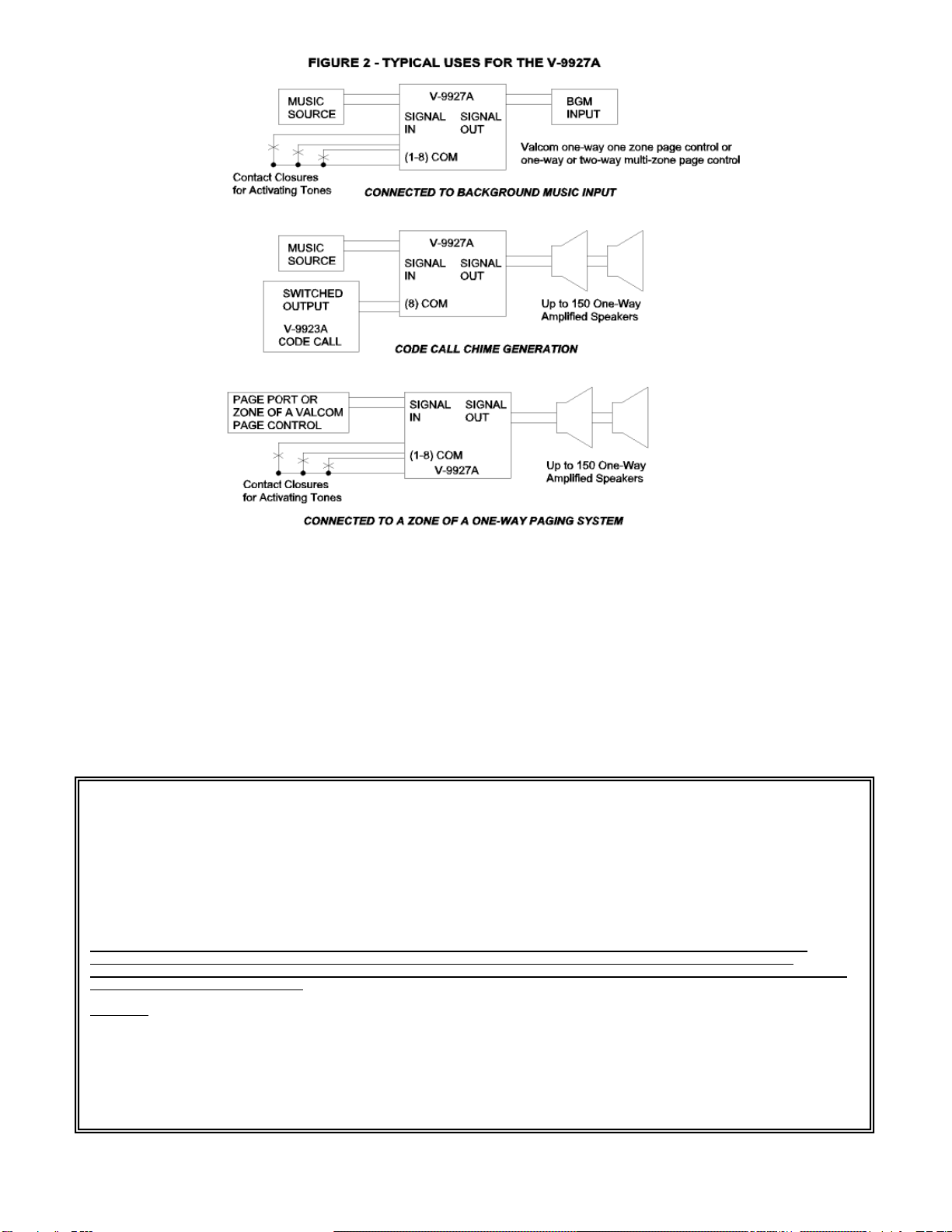
Figure 2 illustrates several of the ways the
V-9927A can be used with other Valcom
equipment.
Code Call Operation
When the V-9927A is connected to the V-9923A
code call unit, the V-9927A will respond to the
contact closure inputs and issue single chimes in
response (See Figure 2).
At the beginning of a Code Call sequence, the
INPUT source will be faded down about 6dB. It
will remain at this level until the CODE CALL
sequence has completed (including the inter digit
time). At that time, the INPUT source will be
faded back up to normal level.
When using the CODE CALL option with other
tone options, the CODE CALL may be
interrupted to place other tones in the sequence
(including Tone #1 with higher priority).
However, the CODE CALL may be out of
sequence for the period that this occurs.
TONE TABLE
NOTE: * denotes V-9927 compatible tones
CONNECTION
ON
OPTION
BLOCK
DESCRIPTION
JP1
P3
COM - TONE 1
COM - TONE 2
COM - TONE 3
COM - TONE 4
COM - TONE 5
COM - TONE 6
COM - TONE 7
COM - TONE 8
IN
IN
IN
IN
IN
IN
IN
IN
* WHOOP, 698 Hz, 3.9 sec (approx.)/cycle 2 cycle min.
* DUAL CHIME, 880 Hz/698 Hz
* BURST, 880 Hz, 1/2 sec on, 2 min.
* STEADY, 880 Hz, 3 sec. min.
TeleBell 986/784 Hz, 11/sec, 10 minimum
Chimes, 986, 784, 659, 523 Hz order
Chimes, 880, 698, 587, 494 Hz order
CODE CALL CHIME, 784 Hz (V-9923A standard)
COM - TONE 1
COM - TONE 2
COM - TONE 3
COM - TONE 4
COM - TONE 5
COM - TONE 6
COM - TONE 7
COM - TONE 8
OUT
OUT
OUT
OUT
OUT
OUT
OUT
OUT
SIREN, 659 Hz, center 1 cycle approx. 0.3 Hz
WHOOP (yelp) 659 Hz, 2.5 Hz, 4 min.
WARBLE, 494/986 Hz, 6 Hz rate
STEADY 698 Hz, 1 sec. minimum
BURST (pulse), 494 Hz, 4.5 Hz rate
Chimes 659/784 Hz
Chimes 986/784 Hz
CODE CALL CHIME, 784 Hz (V-9923A Standard)

947926
3
P2 P3 OUT
IN
BURST
CONT
P4 P1
UNMUTE
MUTE
P5
TONE
LVL
POWER
ON
JP1
1 2 3 4 5 6 7 8 COM SIGNAL
IN COM SIGNAL
OUT GND -24V
TONES
Connect COM to
Desired Tone Relay
Contact
Signal In
(Optional)
Power Supply
-24VDC
(-)
(+)
Signal
Out
Option Blocks (Jumpers shown in factory default setting))
T2
T1
Adjust for
Desired
Output Level
Green LED
on when power
is present
FIGURE 1
OUT
IN
TONE BANK
SELECT
P6
Description of Jumpers
P1 (BURST/CONT) - Sets the mode of the V-9927A. The BURST function allows one (1) tone (or sequence)
for each closure of the TONES input. The CONT function is continuous; the tone (or sequence) will
repeat while the closure on the TONES input (1-8) remains activated.
P2 & P6 - Not used on this version.
P3 (TONE BANK Select; OUT/IN) - Activates tones. Refer to the Tone Table (page 2) to determine jumper
placement for the desired tones.
P4 (UNMUTE/MUTE) - Determines if SIGNAL IN is muted or unmuted. With UNMUTE selected, the signal
returns after completion of a designated tone (or sequence) even if the relay on the TONES input (1-8)
remains connected. With MUTE selected, the signal remains off after completion of tones even if the relay
on the TONES input (1-8) is connected.
P5 (OUT/IN) - Determines the fadeout duration of the Input Source. The INPUT source will be faded out in 0.75
seconds if P5 is OUT or will be faded out in 0.25 seconds if P5 is IN.
Compatibility with the V-9927
Set P3 to "IN" position
Set P1 for BURST or CONT as required
Set P4 to UNMUTE
Set P5 to "IN"
TONE inputs 1-4 correspond to WHOOP,
CHIME, BURST, and STEADY.
CODE CALL is available on TONE input 8.

947926
4
TECHNICAL ASSISTANCE
When trouble is reported, verify the unit in
question is turned on (the green ON LED should
be observed) and all connections are secure.
Assistance in trouble
shooting is available from the factory. When
calling, you should have a VOM available and be
calling from the job site. Call (540) 563-2000
and press 1 for Technical Support, or visit our
website at http://www.valcom.com
Valcom equipment is not field repairable.
Valcom maintains service facilities in Roanoke,
VA. Should repairs be necessary, attach a tag to
the unit clearly stating company name, address,
phone number, contact person, and the nature of
the problem. Send the unit to:
Valcom, Inc.
Repair & Return Dept.
5614 Hollins Road
Roanoke, VA 24019-5056
VALCOM LIMITED WARRANTY
Valcom, Inc. warrants its products only to the original purchaser, for its own use, to be free from defects in materials and workmanship under conditions of normal
use and service for a period of one year from the date of shipment. This Limited Warranty obligation shall be limited to the replacement, repair or refund of any
such defective device within the warranty period, provided that:
1. inspection by Valcom, Inc. indicates the validity of the claim;
2. the defect is not the result of damage, misuse or negligence after the original shipment;
3. the product has not been altered in any way or repaired by others and that factory sealed units are unopened (a service charge plus parts
and labor will be applied to units defaced or physically damaged);
4. freight charges for the return of products to Valcom are prepaid;
5. all units 'out of warranty' are subject to a service charge. The service charge will cover minor repairs (major repairs will be subject to
additional charges for parts and labor).
This Limited Warranty is in lieu of and excludes all other warranties, expressed or implied and in no event shall Valcom, Inc. be liable for any
anticipated profits, consequential damages, loss of time or other losses incurred by the buyer in connection with the purchase, operation,
maintenance, installation, removal or use of the product. The maximum liability of Valcom under this warranty is limited to the purchase price of the
specific Product covered by the warranty.
Disclaimer. Except for the Limited Warranty provided herein, the product is provided “as-is” without any warranty of any kind whatsoever including, without
limitation, any WARRANTY OF MERCHANTABILITY, FITNESS FOR A PARTICULAR PURPOSE OR NON-INFRINGEMENT.
This warranty specifically excludes damage incurred in shipment. In the event a product is received in damaged condition, the carrier should be notified
immediately. Claims for such damage should be filed with the carrier involved in accordance with the F.O.B. point.
Headquarters:
Valcom, Inc.
5614 Hollins Road Roanoke, VA 24019-5056
Phone: (540) 563-2000 FAX: (540) 362-9800
Table of contents
Popular Portable Generator manuals by other brands

Briggs & Stratton
Briggs & Stratton 30255 Illustrated parts list

Profoto
Profoto Pro-B2 user manual

Generac Power Systems
Generac Power Systems GP Series owner's manual

Hyundai
Hyundai HomePower HHD3500 user manual

Power
Power SUA3800iED REV00 owner's manual

kincrome
kincrome BRIGGS & STRATTON KP10107 owner's manual