valent VPR Series Operation and maintenance manual

CONTROLS
INSTRUCTION
OPERATION
& MAINTENANCE
VPR Series
VPRE Series
VPRC/P Series
VPRX Series
IOM-C1-0616
Software Version 4
Part Number 474626

Valent Controls IOM 2 IOM-C1-0616
Part Number 474626

Valent Controls IOM 3 IOM-C1-0616
Part Number 474626
Table of Contents
Table of Contents..............................................................3
Safety .................................................................................4
Control Interfaces .............................................................4
Using the LCD ...................................................................5
Changing a Setpoint .....................................................6
Manually Overriding a Setpoint ....................................7
Changing a Schedule ...................................................7
Changing the IP Address..............................................8
Reviewing BACnet IP or MSTP Settings ......................9
Reviewing LonWorks Settings....................................10
LCD Map ....................................................................11
Using the Universal Maintenance Tool (UMT)..............12
Installing the Software ................................................12
Configuring the IP Address for the PC .......................13
Logging on to the Controller .......................................15
Platform ......................................................................16
Station ........................................................................17
UMT Map....................................................................20
Using the Web User Interface (Web UI) ........................22
Connecting to the Network .........................................22
Configuring the IP Address for the PC .......................22
Logging On to the Web Interface................................22
Changing a Setpoint ...................................................22
Manually Overriding a Setpoint ..................................23
Changing a Schedule .................................................24
Using BACnet Communications....................................25
Using LonTalk Communications ...................................25
Input/Output Points........................................................ 26
34-Point Module......................................................... 26
16-Point Module 1...................................................... 27
16-Point Module 2 (Optional) ..................................... 28
Setpoint List.................................................................... 29
BACnet Setpoint List ..................................................... 34
LonTalk Setpoint List..................................................... 37
Setpoint Descriptions .................................................... 40
Factory Configuration.................................................... 51
Manual Override ............................................................. 52
Alarms ............................................................................. 54
General Alarms .......................................................... 54
Shutdown Alarms....................................................... 55
Resetting Shutdown Alarms....................................... 56
Troubleshooting ............................................................. 57
Refreshing the LCD Screen ....................................... 57
Clearing a Station Error.............................................. 57
Rebooting the Controller ............................................ 57
Locating the Station Folder ........................................ 57
Copying a Station....................................................... 59
Checking Controller Connection ................................ 61
Sequence of Operation .................................................. 63
Warranty.......................................................................... 69
Index ................................................................................ 71

Valent Controls IOM 4 IOM-C1-0616
Part Number 474626
Safety
The customer must provide proper equipment
and fully-trained installers to follow local safety
requirements when receiving, installing, or
servicing equipment. Consult all local building,
electrical, occupational safety, and gas codes.
Lock out all power supplies before servicing the
unit to prevent accidental startup. All fan blades
should be secured to prevent wind rotation.
Remove any restrictive device before restoring
power.
The Clean Air Act of 1990 bans the intentional
venting of refrigerant (CFC and HCFC) as of
July 1, 1992. Approved methods of recovery,
recycling, or reclaiming refrigerant must be
followed. Fines and/or incarceration may be
levied for non-compliance.
WARNING:
Improper installation, adjustment, service,
maintenance, or alteration can cause property
damage, personal injury, or loss of life.
Installation, startup and service must be
performed by a qualified installer, service
agency, or gas supplier.
Control Interfaces
JENEsys Controller
All VPR, VPRE, VPRC/P, and VPRX series units
are equipped with a fully-programmed,
microprocessor-based controller with the
following standard features:
Liquid crystal display (LCD) interface
Internal schedule (may be disabled)
Unit-specific controls sequence
Component safeties and alarms
Ethernet RJ-45 network port
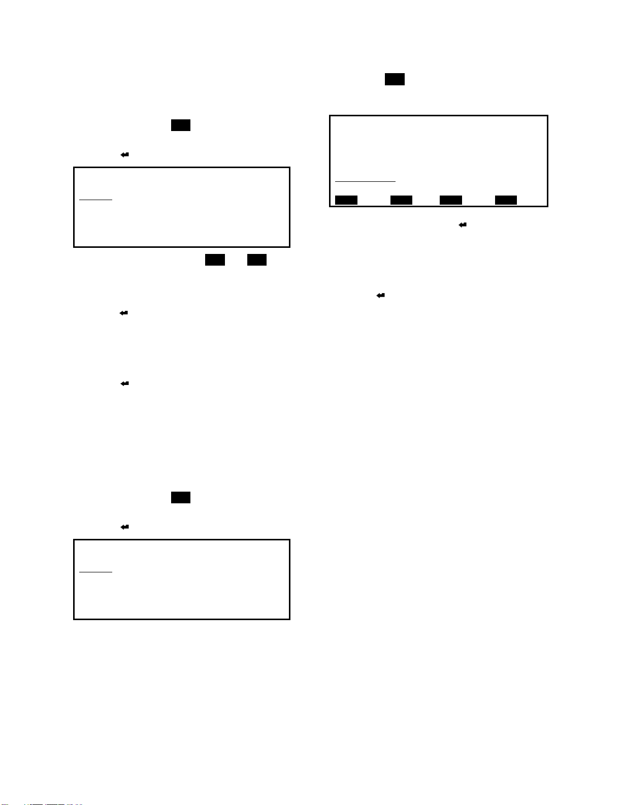
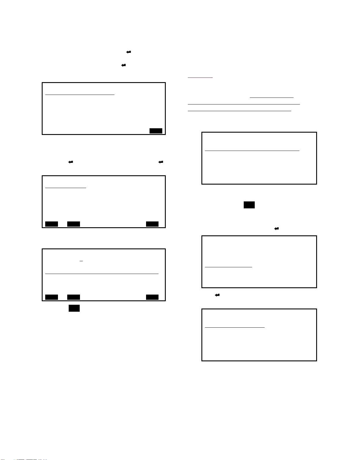
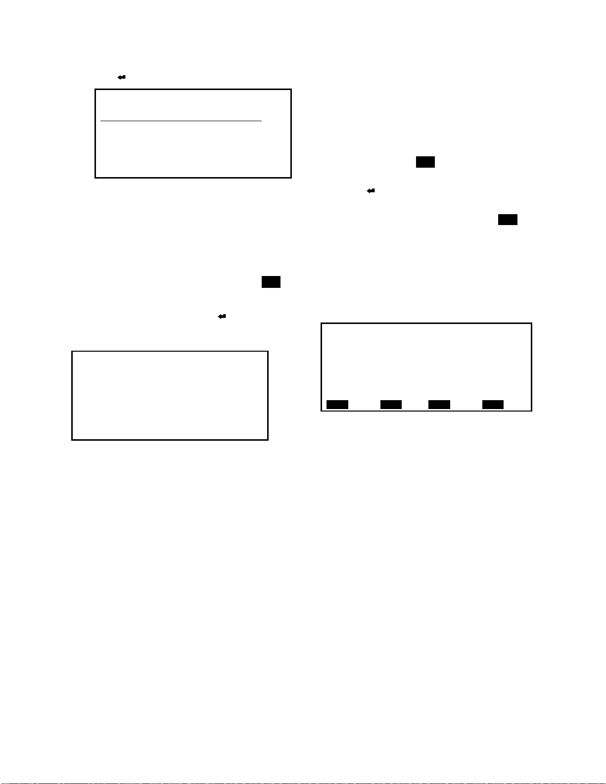
JENEsys Controller
Points, scheduling, and system settings can be
manipulated through an LCD interface or
through a computer running the UMT or Web UI
software.
For 110, 210, 310, and 350 model units, the
control panel is accessible from the service end
of the unit (opposite the outdoor air intake hood).
The LCD interface hangs on the outside of the
electrical panel door.
Universal Maintenance Tool (UMT)
The UMT is a software package that can be
downloaded and installed on any Windows-
based PC. All LCD functions are accessible via
the UMT. The PC is connected via CAT5
Ethernet cable to the LAN1 port on the unit
controller.
Web User Interface (Web UI)
The Web User Interface is an optional, web-
based communication utility for remote
monitoring and setpoint adjustment. Using a
standard web browser, all of the functions
available through the controller’s LCD are
available via the Web UI, but are displayed in a
more advanced graphical interface.

Valent Controls IOM 5 IOM-C1-0616
Part Number 474626
Using the LCD
Keypad Buttons
Seven interface buttons are located on the
bottom and right of the LCD interface. These
buttons are used to navigate through menu
items and between fields, or to change the value
of a field.
Button
Description
▲ and ▼
Use to scroll through items or
to increase or decrease the
value of a selected setpoint.
◄and ►
Use to scroll horizontally through items
or to position the cursor below an
editable setpoint digit. These are also
used for the PREV and NEXT
functions if indicated.
◄◄ and ►►
Use to select the MENU or LAST
command if indicated. The ►►
button is also used to save a
setting.
Use ENTER to select a value or to
enter a value into memory.
dashed underline
This indicates a status-only field.
The value of this field can be
viewed but not changed.
solid underline
The value of this field can be changed.
Menu Commands
The LCD may display on-screen commands,
which can be selected by pressing the arrow
button below it.
Button
Function
PREV
Select this command to go back to the previous
menu.
NEXT
Select this command to go to the next set of menu
options.
MENU
Select this command to return to the main menu.
LAST
Select this command to advance to the last menu.
NULL
Select this command to set the value to Null or
NA. This action is not recommended unless
instructed by the factory.
CANC
Select this command to cancel the current action.
<
Select this command to move one character or
decimal place to the left.
>
Select this command to move one character or
decimal place to the right.
Main Menu
At initial startup or after a power cycle, the
controller requires several minutes to start,
during which time the screen may be blank. The
controller then defaults to the main menu, from
which Points, Scheduling, and System Settings
are available.
Valent LCD Interface
POINTS
SCHEDULING
SYSTEM SETTINGS
The following parameters are accessible. Refer
to the LCD Map on page 11 for a complete list of
all points.
Category
Point/Setting
Points
Unit Status
Alarms
Manual Overrides
Factory Setup
System Status
Cooling
Heating
Fan Operation
Space Pressure Controls
Duct Pressure Control
Damper Operation
Exhaust Settings
Morning Warmup
CO2 Control
Airflow Monitoring
Energy Recovery
Dehumidification
Occupancy
Temperature Setpoints
Headpressure; Heatpump
BMS Interface
Communications
Scheduling
System Schedule
System Settings
Set TCP/IP Settings
System Date
System Time
Time Zone

Valent Controls IOM 6 IOM-C1-0616
Part Number 474626
Changing a Setpoint
1. Push any button on the LCD interface to
refresh the display. If the main menu is not
shown, press the MENU button to return to the
main menu.
2. Press Enter to select POINTS.
Valent LCD Interface
POINTS
SCHEDULING
SYSTEM SETTINGS
3. Use ▲ and ▼ as well as PREV and NEXT to
navigate to the various setpoints stored in
the controller.
4. When the desired setpoint is underlined,
press Enter to change the value.
5. Modifications are made by changing one
significant digit at a time. Use ◄ and ► to
move left and right between digits. Use ▲
and ▼ to change the value of the digit.
6. Press Enter to save the change.
Changing the Fan Speed
Each VPR, VPRE, VPRC/P, and VPRX rooftop
unit includes a variable frequency drive (VFD)
for the supply fan. The supply fan speed can be
changed from the LCD.
1. Push any button on the LCD interface to
refresh the display. If the main menu is not
shown, press the MENU button to return to the
main menu.
2. Press Enter to select POINTS.
Valent LCD Interface
POINTS
SCHEDULING
SYSTEM SETTINGS
3. Use the NEXT button and ► right arrow
button to navigate to the FAN OPERATION
screen.
FAN OPERATION
SUPPLY FAN ON
SUP FAN STATUS ON
SUP FAN SPEED 100 %
SUP FAN MIN 50 %
SUP FAN MAX 80.0 %
EXH FAN ON
MENU PREV NEXT LAST
4. Using the ▼button, move the underscore to
SUP FAN MAX and press Enter on the
keypad.
5. Use ◄ and ► to move left and right
between digits. Use ▲ and ▼ to change the
value of the digit.
6. Press Enter to save the change.
Verifying Changes
After making changes to any VFD parameters,
confirm the VFD/fan speed by enabling the fan
to operate. The speed, in Hz, is indicated on the
front of the VFD display. If the controller is
sending a fan speed of 100%, fan speed analog
output should be 10 VDC and the fan speed
should be the design limit.

Valent Controls IOM 7 IOM-C1-0616
Part Number 474626
Manually Overriding a Setpoint
Many setpoints can be manually overridden for
troubleshooting. Refer to the LCD Map on page
11 for a list of setpoints that can be manually
overridden. Refer to the Manual Override section
on page 52 for definitions of manual override
points.
1. Push any button on the LCD interface to
refresh the display. If the main menu is not
shown, press the MENU button to return to the
main menu.
2. Press Enter to select POINTS.
Valent LCD Interface
POINTS
SCHEDULING
SYSTEM SETTINGS
3. Press ► to navigate to the MANUAL
OVERRIDES screen.
MANUAL OVERRIDES
OVERRIDE MODE DISABLED
TIME REMAINING 0 MIN
UNIT ENABLE OFF
SUPPLY FAN OFF
SUPPLY OVERRIDE OFF
SUPPLY SPEED 50 %
MENU PREV NEXT LAST
4. On the MANUAL OVERRIDES screen,
OVERRIDE MODE is underlined. Press
Enter.
5. Press ▲ to change the value to Enabled.
Press Enter to accept the change.
6. Use ▲ and ▼ to navigate to the setpoint to
override. Press Enter.
7. Use ▲ and ▼ to change the value of the
selection or to change the digit. If applicable,
use ◄ and ► to move left and right between
digits.
8. When the setpoint is modified to the desired
value, push Enter to update the controller.
Wait a few seconds for the value to update.
The controller does not need to be restarted
for the override to take effect.
Manual Override mode is in effect for 4 hours,
after which setpoints return to the previous state
or Auto. To cancel the manual override mode
before it expires, change OVERRIDE MODE to
False. The TIME REMAINING point displays how
much time remains before the override mode
expires automatically.
Changing a Schedule
The default schedule of the controller is 24-hour
Occupied.
1. Push any button on the LCD interface to
refresh the display. If the main menu is not
shown, press the MENU button to return to the
main menu.
2. Press ▼to move the underline cursor to
SCHEDULING and press Enter.
Valent LCD Interface
POINTS
SCHEDULING
SYSTEM SETTINGS
3. When the SCHEDULE menu is shown, press
Enter again. The SCHEDULE DETAILS
screen is then displayed with a seven-day,
24-hour grid.
SCHEDULE DETAILS
TIMES
S
M
T
W
T
F
S
8:00 AM
___
9:00 AM
10:00 AM
11:00 AM
SETTING:
MENU CANC
4. Using the left and right arrows, move the
visible curser to the day a schedule change
is desired. Press Enter to edit an existing
event (if cursor is located on an existing
event) or create a new one (if cursor is
located on an open time slot).

Valent Controls IOM 8 IOM-C1-0616
Part Number 474626
5. If an existing event is selected, the SELECT
EVENT menu appears. Press Enter to edit
the event or ▼ to underline the DELETE
EVENT menu option. Press Enter to delete
the event from the current schedule.
SELECT EVENT
EDIT EVENT 1 - 8:00 AM
DELETE EVENT 1
BACK
6. The event menu is identical whether editing
an existing event or creating a new event.
Use ▲ and ▼ to select the desired field and
press Enter to change its value. Press
Enter to complete the change.
MONDAY EVENT
START TIME: 8:00 AM
END TIME: 10:00 AM
VALUE: OCCUPIED
MENU SAVE CANC
7. To temporarily disable an event, change the
Value field from OCCUPIED to UNOCCUPIED.
MONDAY EVENT
START TIME: 8:00 AM
END TIME: 10:00 AM
VALUE: UNOCCUPIED
MENU SAVE CANC
8. Press SAVE to save the settings in the
controller.
Any request for occupancy from the push button
on a space temperature sensor will be effective
for two hours.
Changing the IP Address
The local display may be used to change the
default network settings of the controller.
WARNING:
Setting the IP address to an incorrect value may
cause the controller to lock up and may require
replacing the controller. Make sure the IP
address, gateway, and subnet mask are set
correctly before saving the new settings.
The controller ships with the following default
settings:
JENESYS TCP/IP SETTINGS
IP ADDRESS: 192.168. 1.101
SUBNETMASK: 255.255.255. 0
GATEWAY: 192.168. 1. 1
MENU SAVE
1. Push any button on the LCD interface to
refresh the display. If the main menu is not
shown, press the MENU button to return to the
main menu.
2. Press ▼ to move the underline cursor to
SYSTEM SETTINGS and press Enter.
Valent LCD Interface
POINTS
SCHEDULING
SYSTEM SETTINGS
3. Press Enter to select SET TCP/IP
SETTINGS.
JENESYS SYSTEM SETTINGS
SET TCP/IP SETTINGS
SYS DATE: AUG 17, 2012
SYS TIME: 15:02
TIMEZONE: AMERICA/CHICA
(-5/-6)
MENU CANC

Valent Controls IOM 9 IOM-C1-0616
Part Number 474626
4. Press Enter to select IP ADDRESS.
JENESYS TCP/IP SETTINGS
IP ADDRESS: 192.168. 1.200
SUBNETMASK: 255.255.255. 0
GATEWAY: 192.168. 1. 1
MENU SAVE
5. Use ◄ and ► to move left and right
between digits. Use ▲ and ▼ to change the
value of the digit.
The subnet mask and gateway can be
changed using a similar method. A
corresponding gateway must be entered for
the IP address.
6. When all changes are complete, select SAVE.
The display will indicate that a reboot is
required. Move the cursor under the desired
response (YES/NO) and press Enter. Allow
several minutes for the controller to reboot
and return to normal operation.
-REBOOT-
CONTROLLER MUST
REBOOT TO SAVE
THESE SETTINGS
CONTINUE?
YES NO
Reviewing BACnet IP or MSTP Settings
The JENEsys controller’s BACnet IP and MSTP
settings are available in the POINTS menu of the
LCD. To access them:
1. Push any button on the LCD interface to
refresh the display. If the main menu is not
shown, press the MENU button to return to the
main menu.
2. Press Enter to select POINTS. The Unit
Status menu is the first menu displayed.
3. Press the right double arrows below LAST to
jump to the last tab of the points menu,
which is for COMMUNICATIONS.
BACnet is an optional feature which must be
licensed. Although data will appear for viewing
on the communication menu, settings cannot be
changed if the unit has not been licensed.
COMMUNICATIONS
COMM LICENSE BACNET IP
****BACNET *****
OBJECT ID 11
NETNUMBER IP 1
NETNUMBER MSTP 2
MSTP ADDRESS 1
MENU PREV NEXT LAST
4. Make sure that COMM LICENSE is the same
as the protocol you have purchased and all
other settings are set as desired. Verify that
your device can be discovered at your head-
end system.
Refer to Using BACnet Communications on page 25
for further information about BACnet
communications.

Valent Controls IOM 10 IOM-C1-0616
Part Number 474626
Reviewing LonWorks Settings
The LonWorks settings for the JENEsys
controller are available in the POINTS menu of
the LCD display. To access them:
1. Push any button on the LCD interface to
refresh the display. If the main menu is not
shown, press the MENU button to return to the
main menu.
2. Press Enter to select POINTS. The UNIT
STATUS menu is the first menu displayed.
3. Press the right arrows below LAST to jump to
the last tab of the points menu, which is for
COMMUNICATIONS.
4. Use ▼ to scroll down to reach the LonTalk
points.
LonTalk is an optional feature which must be
licensed. Although data will appear for viewing
on the communications menu, settings cannot
be changed if the unit has not been licensed.
COMMUNICATIONS
BAUDRATE 9600
MAX MASTERS 127
MAX INFO FRAMES 20
****LONTALK *****
NID 04 1E 0F E8 03 00
SERVICE PIN FALSE
MENU PREV NEXT LAST
Service Pin
The SERVICE PIN is available to help discover
the Valent unit on the building’s LON network.
1. On the LonWorks menu, navigate to
SERVICE PIN.
2. Press Enter to make the point editable.
Toggle ▲ or ▼ to make the value TRUE,
then press Enter. This sends a service pin
signal over the LON network. This can be
repeated as many times as necessary.
Refer to Using LonTalk Communications on page 25
for further information about LonTalk
communications.

Valent Controls IOM 11 IOM-C1-0616
Part Number 474626
LCD Map
This list contains all points accessible on the LCD, in the menu order and list order in which they appear
on the screen. Setpoints in this list with a solid underline can be edited. All others are view-only. On the
LCD screen, a solid cursor underline indicates an editable setpoint; a dashed cursor underline indicates a
view-only point. These points are also accessible from the UMT or Web UI. Refer to the following sections
for more information: Setpoint List on page 29 and Setpoint Descriptions on page 40.
UNIT STATUS
ALARMS
MANUAL
OVERRIDES
FACTORY SETUP
SYSTEM STATUS
COOLING
HEATING
FAN OPERATION
SUPPLY TEMP
DX COIL TEMP
SPACE TEMP
SPACE RH
SPACE ENTH
OA TEMP
OUTDOOR RH
OUTDOOR ENTH
EXHAUST TEMP
MIXED AIR TEMP
RESET
ALARM STATUS
SHUTDOWN INPUT
SUPPLY FAN
DAMPER SWITCH
SUPPLY TEMP SEN
HIGH SUP TEMP
LOW SUP TEMP
SPACE STATIC
DUCT STATIC
HPC_LPC_A
HPC_LPC_B
REF PRESSURE A
REF PRESSURE B
SPACE TEMP
OA TEMP
OA HUMIDITY SEN
EXHAUST TEMP
MIXED TEMP SEN
EXHAUST FAN
SPACE HUMIDITY
CO2 SENSOR
HW ROTATION
FILTERS
WSHP REF LOW PSI
FREEZESTAT
OVERRIDE MODE
TIME REMAINING
UNIT ENABLE
SUPPLY FAN
SUPPLY OVERRIDE
SUPPLY SPEED
EXHAUST FAN
EXHAUST OVERRIDE
EXHAUST SPEED
HEAT WHEEL
WHEEL OVERRIDE
WHEEL SPEED
OA DAMPER CTRL
OA DMP OVERRIDE
HEAT COOL
COMPRESSOR1
COMPRESSOR2
COMPRESSOR3
COMPRESSOR4
DIGITAL SCROLL
MOD HEAT
ELEC HEAT
HEAT 1
HEAT 2
HEAT 3
SPACE SETPT
SUPPLY SETPT
HOT GAS REHEAT
REHEAT OVERRIDE
FLAT PLATE
F PLATE OVERRIDE
PRE-HEATER
COIL SAFETY
HEAD PRESSURE
FAN VFD/VALVE A
FAN VFD/VALVE B
REVERSING VALVE
REVERSING VALVE
COMM VAL
DAMPER CONFIG
FAN CONFI
CO2 CTRL VAL
EX FAN CTRL
REM DAMPER
PRE-HEATER
AIR MEAS VAL
HEAT VAL
COOL VAL
ENERGY RECOV
UNIT TYPE
ECONO
AMD TYPE
WEB UI
RE MON
OPTIMAL SS
HEAT PUMP
MWU
NIGHT PURGE
REHEATDEHUM
HW ROTATION
SPACE SETPOINT
FUTURE
FUTURE
I/O MAP
VERSION
SO#
TAG
SYSTEM ENABLE
SYSTEM STATUS
SYSTEM START
END SWITCH
STATUS
OCC BY
OP MODE
COOLING PID
HEATING PID
ECON PID
ECON STATUS
REHEAT OUTPUT
REVERSING VLV
HP HEAT PID
CHW/DIGITAL OUT
COMP 1
COMP 2
COMP 3
COMP 4
AMB LOCKOUT
DEHUM STATUS
ELECTRIC
MODULATING
STAGE 1
STAGE 2
STAGE 3
AMB LOCKOUT
HW CASE HEAT ENABLE
HW CASE HEAT SPT
SUPPLY FAN
SUP FAN STATUS
SUP FAN SPEED
SUP FAN MIN
SUP FAN MAX
EXH FAN
EXH FAN STATUS
EXH FAN SPEED
SPACE PRESSURE
CONTROL
DUCT PRESSURE
CONTROL
DAMPER
OPERATION
EXHAUST SETTINGS
MORNING
WARMUP
CO2 CONTROL
AIR FLOW
MONITORING
ENERGY RECOVERY
PRESSURE
SETPOINT
HIGH LIMIT
SUPPLY REACTION
EXHAUST REACTION
PRESSURE
SETPOINT
HIGH LIMIT
SUPPLY REACTION
OA DAMPER
DAMPER CONFIG
OAD MIN POS
OAD MAX POS
ENTHALPY SETPT
DRY BULB SPT
ECONO
EX FAN DAMP POS
EX FAN MAX SPEED
EX FAN MIN SPEED
EX SPEED OFFSET
ENABLE
WARM UP STATUS
CO2 LEVEL
INSTALLED
SETPOINT
SUPPLY
EXHAUST
AMD
SETPOINT
WHEEL STATUS
WHEEL OUTPUT
ENERGY RECOV
PREHEAT
DEFROST MODE
DEHUMIDIFICATION
OCCUPANCY
TEMPERATURE
SETPOINTS
HEADPRESSURE;
HEATPUMP
BMS INTERFACE
COMMUNICATIONS
DX COIL SETPT
SPACE RH SPT
OA DEWPOINT SPT
OCC STATUS
OCC BY
SCHEDULE
SPACE SETPT
SPT SLIDER
SPACE OFFSET
SUPPLY CALC
SUPPLY SETPT
SUPPLY MIN COOL
SUPPLY MIN HEAT
SUPPLY MAX COOL
SUPPLY MAX HEAT
UNOCC HEAT
UNOCC COOL
SUPPLY CONTROL
LOCAL ADJUST DISABLE
HEAD PRESSURE
HEAD PRESSURE
COMP OFFVLVPOS
WSHP SUC LOWLIM
VALVE A OUTPUT
VALVE B OUTPUT
PRESSURE CIRC A
PRESSURE CIRC B
ASHP
OAT
OA RH%
SPACE TEMP
SPACE RH
CO2
SPACE STATIC
DUCT STATIC
SF OVERRIDE
SF SPEED
EF OVERRIDE
EF SPEED
OAD OVERRIDE
OAD POS
OCC ENABLE
BAS OCC CMD
HEAT DISABLE
COOL DISABLE
SHUTDOWN
SPACE SETPOINT
RH SETPOINT
S STATIC SETPOINT
SUPPLY SETPOINT
D STATIC SETPOINT
CO2 SETPOINT
UNOCC COOL SPT
UNOCC HEAT SPT
UNOCC HUMID SPT
COMM LICENSE
****BACNET
OBJECT ID
NETNUMBER IP
NETNUMBER MSTP
MSTP ADDRESS
BAUDRATE
MAX MASTER
MAX INFO FRAMES
****LONTALK
NID
SERVICE PIN

Valent Controls IOM 12 IOM-C1-0616
Part Number 474626
Using the Universal Maintenance Tool (UMT)
Installing the Software
The JENEsys PC3000e requires an updated
version of the UMT and cannot be configured
using the same UMT as was used with the
PC1000.
Download and install the new UMT prior to
arriving at the job site. The software must be
installed on a Windows-based PC, and runs the
best using a Windows XP-based operating
system.
PC3000e UMT 3.8.U1 (also known as UMT 3.8.110)
First Ship Date: June 15, 2016 (approximately)
Download: https://www.dropbox.com/sh/4caowjsfd5x7sd2/AADUpJX86cI0dmLMxa1b1ZVba?dl=0
Password: Viper-jene
Installation Instructions: described in the following section
PC1000 UMT 3.6.406
Last Ship Date: June 14, 2016 (approximately)
Download: https://www.dropbox.com/sh/7pbdqy4nrfwxef8/AAC7HB3UIs4fDjLZ0QkbfyDaa?dl=0
Password: Viper-jene
Installation Instructions: V3 Controls IOM –available for download using link above.
It is likely that both versions of the UMT will be installed on a service technician’s laptop. There are no
know issues with having two versions of the UMT installed on a single laptop. Contact Valent Service for
assistance and use of either UMT version.
CAUTION:
UMT 3.8.U1 (UMT 3.8.110) is compatible with PC3000e controllers only.
UMT 3.6.406 is compatible with PC1000 controllers only.
Connecting to the Controller
Connect the computer to the JENEsys controller
using a CAT5 Ethernet cable. The computer
should be connected through its LAN connection
(Ethernet port). The controller should be
connected using the LAN1 port as shown in the
following figure.

Valent Controls IOM 13 IOM-C1-0616
Part Number 474626
Configuring the IP Address for the PC
To successfully connect with the Valent unit
controller, the IP address of the PC must be in
the same range as the controller, but not
identical. Every Valent unit is shipped from the
factory with the same default IP address:
192.168.1.101 [Valent unit]
A suggested IP address for the computer
communicating with the Valent unit is:
192.168.1.200 [PC]
Configuring the IP Address Using Windows XP
To change the static IP address of the PC that is
running Windows XP, follow these steps.
1. Click START or the Windows icon in the
lower left corner of the screen.
2. Select Control Panel.
3. Select Network Connections.
4. Identify the target LAN connection with the
status of Network cable unplugged.
5. Right-click on the identified Local Area
Connection. Select Properties.
6. Use the slider bar to scroll down until the
selection Internet Protocol (TCP/IP) is
visible.
7. Highlight Internet Protocol (TCP/IP) and
press the Properties button.
8. To assign a new IP address manually, click
on Use the following IP address.
9. Type in the following information and press
OK when completed.
IP address: 192.168.1.200
Subnet mask: 255.255.255.0
If the controller does not connect, return to
this screen and, in addition to the previous
fields, enter the following:
Default gateway: 192.168.1.1
10. The system returns to the Local Area
Connection Properties screen. Click on
Close to exit this screen.

Valent Controls IOM 14 IOM-C1-0616
Part Number 474626
The IP address of the Valent unit controller can
be changed to be in the same range as the
connected PC as well, especially for instances
when the PC and Valent unit are connected to
the building’s network/LAN. In those cases,
request a static IP address from the network
administrator and use the LCD or UMT to edit
the address of the Valent unit.
Configuring the IP Address Using Windows 7
To change the static IP address of the PC that is
running Windows 7, follow these steps.
1. Click on the Windows orb icon in the lower
left corner of the screen:
2. Select Control Panel.
3. Select Network and Sharing Center.
If the Control Panel is displayed by category,
select View Network Status and Tasks in the
Network and Internet category.
4. On the network screen, choose Change
adapter settings.
5. Find your Local Area Connection. If you
need to determine which connection to
select, simply unplug the network cable from
the PC. The adapter status should change
to Not Connected. Reconnect the cable.
6. Right click on the Local Area Connection,
then select Properties.

Valent Controls IOM 15 IOM-C1-0616
Part Number 474626
7. Select TCP/IPv4, then click on Properties.
8. On the TCP/IPv4 screen, click on Use the
following IP address.
Enter the following in the text boxes:
IP address: 192.168.1.200
Subnet mask: 255.255.255.0
If the controller does not connect, return to
this screen and, in addition to the previous
fields, enter the following:
Default gateway: 192.168.1.1
9. Press OK to save the settings.
Logging on to the Controller
1. Start the UMT software program by double
clicking on the icon on the Windows
desktop.
2. During startup, the UMT checks for
JENEsys-based controllers on the current
network.
3. When the controller is identified, double-click
on the controller name to continue. Or click
on the controller name, then click OK at the
bottom of the window.
If a controller is not found on the network,
verify the IP settings for both the laptop and
the controller. They should be in the same
range, but not the same.
NOTE: On occasion the JENEsys controller
will not announce itself. If this happens,
press Cancel on the Search window. On the
Connect screen, manually type in the IP
address of the JENEsys controller with all of
the settings shown in the table below, then
press Connect.
Occasionally, if the controller has been
running for a long period, the Ethernet port
goes to sleep and loses connection. Reboot
the controller to reconnect.
4. The Connect screen is displayed. Two
options are available for connecting:
Platform and Station. Select Platform to
copy stations and set the IP address. Select
Station for schedule and setpoint
adjustments.
5. Enter the following items. Usernames and
passwords are case sensitive.
IP Address
192.168.1.101
Platform Port
3011
Platform Username
tridium
Platform Password
niagara
Fox Port
1911
Fox Username
admin
Fox Password
[blank]

Valent Controls IOM 16 IOM-C1-0616
Part Number 474626
6. Click on the Connect button to establish the
connection between the computer (via UMT)
and the controller.
The UMT software package will connect to the
selected unit and download data from the
individual station. Monitor the progress bar on
the screen for the status of this operation. The
download process should take several minutes.
Platform
When logging into the Platform option, the
Station Director tab is the first screen displayed.
Refer to the UMT Map on page 20 for a complete
list of all points accessible on the UMT.
Platform Administration
Changing the IP Address
Use the TCP/IP Configuration utility to edit the
network address and related parameters for the
controller.
WARNING:
Setting the IP Address to an incorrect value may
cause the controller to lock up and will require
replacing the controller. Make sure the IP
address, gateway, and subnet mask are set
correctly before saving the new settings.
The controller ships with the following default
settings:
JENESYS TCP/IP SETTINGS
IP ADDRESS: 192.168. 1.101
SUBNETMASK: 255.255.255. 0
GATEWAY: 192.168. 1. 1
MENU SAVE

Valent Controls IOM 17 IOM-C1-0616
Part Number 474626
1. Select the TCP/IP Configuration tab.
2. Expand Interface 1 by clicking on the double
arrows to the right of the title.
IMPORTANT:
Do not change the parameters for Interface
2.
3. Edit the Gateway, IP Address, and Subnet
Mask as required, then click on Save
TCPIP.
IMPORTANT:
Do not select Enabled for DHCP; this can
make the controller difficult to access.
4. A pop-up message asks for confirmation to
reboot the controller. Select Yes.
5. A pop-up message confirms that the
controller is rebooting. Select OK. Allow
several minutes for the controller to reboot.
6. Disconnect from the controller and
reconnect if desired.
IMPORTANT:
When the IP Address has been changed, the
controller can only be accessed by connecting
through the new address. If the address is lost
or forgotten, the controller may not be
accessible. Before rebooting, record the new
controller address in a convenient location.
Station
Checking Unit Status
Select the Unit Status tab to see a summary of
the temperature inputs to the unit controller.

Valent Controls IOM 18 IOM-C1-0616
Part Number 474626
Changing a Setpoint
1. To change a setpoint, select the appropriate
tab.
For example, to change the space
temperature, select the Temperature
Setpoints tab.
2. Click to move the cursor into the setpoint
field.
3. Enter a new setpoint.
4. Click on the Save button at the bottom of the
screen.
Changing the Fan Speed
Each VPR, VPRE, VPRC/P, and VPRX rooftop
unit includes a variable frequency drive (VFD)
for the supply section. The supply fan speed can
be changed from the UMT.
1. Select the Fan Operation tab.
2. If the Writable Points are not visible, click on
the double arrows by the heading.
3. Locate the Supply Fan Max Speed Setpoint.
Click to move the cursor into the setpoint
field.
4. Enter a new maximum fan speed.
5. Click on the Save button at the bottom of the
list.
Manually Overriding a Setpoint
Many setpoints can be manually overridden
during troubleshooting. Refer to the Manual
Override section on page 52 for definitions of
override points.
1. To override a setpoint, select the Manual
Overrides tab.
2. Set Enable Override to Enabled.
3. Click to move the cursor into the desired
setpoint field. Enter a new value or change
the state.
4. Click on the Save button at the bottom of the
setpoint list.
A Manual Override is in effect for 4 hours, after
which setpoints return to the previous state or
Auto. To stop an override, set the point to Auto.
To cancel the manual override mode before it
expires, set Enable Override to Disabled.

Valent Controls IOM 19 IOM-C1-0616
Part Number 474626
Changing a Schedule
1. To edit a schedule, select the Occupancy
tab.
The occupied hours of operation are
displayed for each day of the week. The
default schedule in the controller is 24-hour
Occupied.
2. To edit the schedule, use the mouse to drag
the start/stop times for each day. Simply
click on the dividing line in the column and
push it up or down to a new time. Event
Start and Event Finish times can also be
edited directly using the fields near the
bottom of the screen.
3. When the changes are complete, press
Save at the bottom of the screen.
Scheduling a Special Event
A one-time exception to the regular weekly
schedule can be configured as a special event.
1. Click on the Special Events tab at the
bottom of the Schedule screen.
2. On the calendar at the top of the screen,
click on the day to schedule a special event.
3. Enter the occupied and unoccupied times on
the right side of the display in the same
manner a regular schedule would be
configured.
4. Click Save at the bottom of the screen.
The new settings will be valid only on the day
specified.
Viewing Schedule Properties
From the Schedule screen, click on the
Properties tab at the bottom of the screen.
Information on the Properties tab should be
changed only under direction of the factory.
Viewing the Schedule Summary
From the Schedule screen, click on the
Summary tab. Click on a date to see a summary
of all schedule settings for that day, including the
weekly settings and any special events.

Valent Controls IOM 20 IOM-C1-0616
Part Number 474626
UMT Map
This list contains all points accessible on the UMT. Setpoints in this list with a solid underline can be
edited. All others are view-only.
AIR FLOW MONITORING
AMD Airflow
AMD Damper Area
AMD K Factor
AMD M Factor
AMD Thermal Dispersion Max Velocity
AMD Transducer Range
Damper Setpoint
Exhaust Airflow
Exhaust Inlet Cone K Factor
Supply Airflow
Supply Inlet Cone K Factor
Type
ALARMS
Alarm Reset
Alarm Status
Clogged Air Filter
CO2 Sensor
Duct Static Pressure
Exhaust Fan
Exhaust Temperature Sensor
Freezestat
Heat Wheel Rotation
High Pressure/Low Pressure Cutout Circuit A
High Pressure/Low Pressure Cutout Circuit B
Mixed Air Temperature Sensor
Outdoor Air Damper End Switch
Outdoor Air Temperature Sensor
Outdoor Relative Humidity Sensor
Refrigerant Pressure Transducer A
Refrigerant Pressure Transducer B
Shutdown Input
Space Humidity Sensor
Space Static Pressure
Space Temperature Sensor
Supply Fan
Supply High Temp Alarm Delay
Supply Temp High
Supply Temp Low
Supply Temperature Sensor
WSHP Low Refrigerant Pressure
BACNET NETWORK ADVANCED
Time Synch
UDP Port Number
CO2 CONTROL
CO2 Control
CO2 Deadband
CO2 Level
CO2 Setpoint
Control Enabled
Maximum Damper Control Position
COOLING
10 Volts Opens Chilled Water Valve
AMB Lockout
Chilled Water Valve Off Position
Compressor 1 Ambient Lockout Setpoint
Compressor 1 Output
Compressor 2 Ambient Lockout Setpoint
Compressor 2 Output
Compressor 3 Ambient Lockout Setpoint
Compressor 3 Output
Compressor 4 Ambient Lockout Setpoint
Compressor 4 Output
Cooling Execution Time
Cooling Integral Constant
Cooling Proportional Constant
Digital/Chilled Water Output
Enable Compressor 1 Ambient Lockout
Enable Compressor 2 Ambient Lockout
Enable Compressor 3 Ambient Lockout
Enable Compressor 4 Ambient Lockout
High/Low Pressure Trip Shutdown Circuit
Shutdown Unit During High/Low Pressure Trip
DAMPER OPERATION
Damper Configuration
Damper Output
Damper Remote Control
Economizer Configuration
Economizer Enable Setpoint Enthalpy
Economizer Enable Setpoint Temperature
Outdoor Air Damper Maximum
Outdoor Air Damper Minimum
Unoccupied Outdoor Air Damper Minimum
DEHUMIDIFICATION
Dehumidification Has Priority
DX Coil Setpoint
Occupied Space Humidity Low Deadband
Outdoor Dewpoint Deadband
Outdoor Dewpoint Setpoint
Overcool Offset
Space Dewpoint Dehumidification Cutout
Space Relative Humidity Setpoint
Unoccupied Space Humidity Low Deadband
Unoccupied Space Humidity Setpoint
DUCT PRESSURE CONTROL
Duct Pressure
Duct Pressure High Limit Setpoint
Duct Pressure Setpoint
Supply Fan Reaction Speed
ENERGY RECOVERY
Defrost Mode
Flat Plate Exhaust Defrost
Heat Wheel Exhaust Defrost
Heat Wheel Operating Mode
Heat Wheel Output
Heat Wheel Speed/Damper Position
Heat Wheel Status
HW Jog Duty Cycle
HW Jog Period
HW Speed When Economizing
Preheat Ambient Setpoint
Preheat Output
EXHAUST SETTINGS
Configuration
Exhaust Fan Enable Damper Position
Exhaust Fan Max Speed
Exhaust Fan Min Speed
Exhaust Fan Offset
FACTORY SETUP
Airflow Monitoring Type
AMD Type
CO2 Control
Communications Type
Cooling Package
Damper Configuration
Economizer
Energy Recovery Configuration
Exhaust Fan Control Type
Future
Future
Heat Pump
Heat Wheel Rotation Sensor
Heating Package
I/O Map
Morning Warm Up
Night Purge
Optimal SS
Pre-Heater
Refrigerant Monitoring
Reheat Dehumidification
Remote Damper Control
Saved Controls Number
Space Setpoint
Supply Fan Configuration
Unit Type
Web UI
FAN OPERATION
Exhaust Fan Output
Exhaust Fan Speed
Exhaust Fan Status
Supply Fan Max Speed Setpoint
Supply Fan Min Speed
Supply Fan Output
Supply Fan Speed
Supply Fan Status
Unoccupied Supply Fan Speed Offset
HEAD PRESSURE;HEAT PUMP
1.0 Air Cooled Head Pressure Setpoint
2.0 Air Cooled Head Pressure
Dehumidification Setpoint
2.0 Air Cooled Head Pressure Setpoint
ASHP Allow Defrost Mode
ASHP Defrost Cancel Condensing Setpoint
ASHP Defrost Status
ASHP Electric Heat Defrost
ASHP Electric Heat Defrost Enable :
CALL VALENT FOR PASSWORD
ASHP Low Ambient Compressor Lockout Setpoint
Head PR Output 1
Head PR Output 2
Refrigerant Pressure Circuit A
Refrigerant Pressure Circuit B
Valve A Output
Valve B Output
WSHP Cold Start Duration
WSHP Cold Start Enable Temp
WSHP Compressor Off Water Valve Position
WSHP Condenser Temperature Setpoint
WSHP Suction Temp Low Limit Safety
WSHP Valve Max Closed Position
This manual suits for next models
3
Table of contents
Popular Industrial Equipment manuals by other brands

Gunnebo
Gunnebo Wedge K12 Additional Installation, Operation and Maintenance Instructions

Graco
Graco SERIES J Instructions-parts list

SCHUNK
SCHUNK PGF 50 Assembly and operating manual

NORD-LOCK
NORD-LOCK Superbolt NXT Series quick start guide

Pfeiffer Vacuum
Pfeiffer Vacuum FullRange PKR 251 operating instructions

Charnwood
Charnwood PT250 owner's manual